wheel bolt torque FORD SIERRA 1991 2.G Suspension And Steering User Guide
[x] Cancel search | Manufacturer: FORD, Model Year: 1991, Model line: SIERRA, Model: FORD SIERRA 1991 2.GPages: 20, PDF Size: 0.94 MB
Page 13 of 20

5Refitting is a reversal of removal, with
reference to the note at the beginning of this
Section. Refit any shims in their original noted
positions, and tighten all bolts to the specified
torque.
Removal
1Loosen the rear roadwheel nuts, chock the
front wheels, jack up the rear of the vehicle
and support on axle stands placed under the
side members.
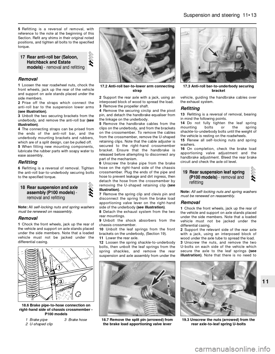
2Prise off the straps which connect the
anti-roll bar to the suspension lower arms
(see illustration).
3Unbolt the two securing brackets from the
underbody, and remove the anti-roll bar (see
illustration).
4The connecting straps can be prised from
the ends of the anti-roll bar, and the
underbody mounting brackets and rubbers,
which are of a split design, can be pulled off.
5When fitting new mounting components,
lubricate the rubber parts with soapy water to
ease assembly.
Refitting
6Refitting is a reversal of removal. Tighten
the anti-roll bar-to-underbody securing bolts
to the specified torque.
Note: All self-locking nuts and spring washers
must be renewed on reassembly.
Removal
1Chock the front wheels, jack up the rear of
the vehicle and support on axle stands placed
under the side members. Note that a loaded
vehicle must not be jacked under the
differential casing.2Support the rear axle with a jack, using an
interposed block of wood to spread the load.
3Remove the propeller shaft.
4Remove the securing circlip and the pivot
pin, and detach the handbrake equaliser from
the linkage on the underbody.
5Remove the handbrake cables from the
clips on the underbody, and from the brackets
on the crossmember. To remove the cables
from the crossmember, remove the U-shaped
retaining clips. Note that the cable adjuster is
secured to the right-hand crossmember
bracket. Ensure that the handbrake is
released before attempting to disconnect any
part of the mechanism.
6Unscrew the brake pipe from the brake
hose on the right-hand side of the chassis
crossmember. Plug the ends of the pipe and
hose to prevent leakage and dirt ingress, then
detach the hose from the crossmember by
removing the U-shaped retaining clip (see
illustration).
7Remove the spring clip and clevis pin and
disconnect the spring from the brake load
apportioning valve lever on the right-hand
side of the underbody (see illustration).
8Detach the exhaust system from the two
rear mountings.
9Unbolt the shock absorbers from the
chassis crossmember.
10Unbolt the leaf springs from the front
brackets on the underbody, (Section 19).
11Lower the rear axle.
12Loosen the spring shackle-to-underbody
bolts, then unbolt the leaf springs from the
spring shackles, and remove the rear
suspension and axle assembly from under thevehicle, guiding the handbrake cables over
the exhaust system.
Refitting
13Refitting is a reversal of removal, bearing
in mind the following points.
14Do not fully tighten the leaf spring
mounting bolts or the spring
shackle-to-underbody bolts until the weight of
the vehicle is resting on the roadwheels.
15Renew all self-locking nuts and spring
washers.
16On completion, check the brake load
apportioning valve adjustment and the
handbrake adjustment. Bleed the rear brake
circuit and check the axle oil level.
Note: All self-locking nuts and spring washers
must be renewed on reassembly.
Removal
1Chock the front wheels, jack up the rear of
the vehicle and support on axle stands placed
under the side members. Note that a loaded
vehicle must not be jacked under the
differential casing.
2Support the relevant side of the rear axle
with a jack, using an interposed block of
wood under the axle tube to spread the load.
3Unscrew the nuts, and remove the two
U-bolts on each side of the vehicle which
secure the axle to the leaf springs (see
illustration). Note that there is no need to
19Rear suspension leaf spring
(P100 models) - removal and
refitting
18Rear suspension and axle
assembly (P100 models) -
removal and refitting
17Rear anti-roll bar (Saloon,
Hatchback and Estate
models) - removal and refitting
Suspension and steering 11•13
11
17.3 Anti-roll bar-to-underbody securing
bracket
18.7 Remove the split pin (arrowed) from
the brake load apportioning valve lever
18.6 Brake pipe-to-hose connection on
right-hand side of chassis crossmember -
P100 models
1 Brake pipe
2 U-shaped clip3 Brake hose
17.2 Anti-roll bar-to-lower arm connecting
strap
19.3 Unscrew the nuts (arrowed) from the
rear axle-to-leaf spring U-bolts
Page 14 of 20

disconnect the shock absorber from the
U-bolt counterplate.
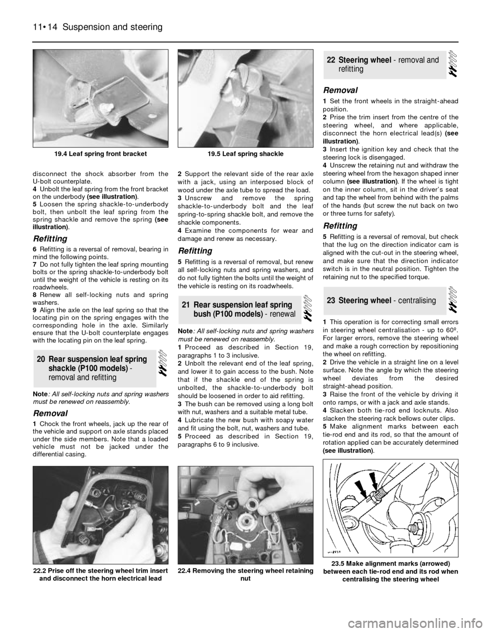
4Unbolt the leaf spring from the front bracket
on the underbody (see illustration).
5Loosen the spring shackle-to-underbody
bolt, then unbolt the leaf spring from the
spring shackle and remove the spring (see
illustration).
Refitting
6Refitting is a reversal of removal, bearing in
mind the following points.
7Do not fully tighten the leaf spring mounting
bolts or the spring shackle-to-underbody bolt
until the weight of the vehicle is resting on its
roadwheels.
8Renew all self-locking nuts and spring
washers.
9Align the axle on the leaf spring so that the
locating pin on the spring engages with the
corresponding hole in the axle. Similarly
ensure that the U-bolt counterplate engages
with the locating pin on the leaf spring.
Note: All self-locking nuts and spring washers
must be renewed on reassembly.
Removal
1Chock the front wheels, jack up the rear of
the vehicle and support on axle stands placed
under the side members. Note that a loaded
vehicle must not be jacked under the
differential casing.2Support the relevant side of the rear axle
with a jack, using an interposed block of
wood under the axle tube to spread the load.
3Unscrew and remove the spring
shackle-to-underbody bolt and the leaf
spring-to-spring shackle bolt, and remove the
shackle components.
4Examine the components for wear and
damage and renew as necessary.
Refitting
5Refitting is a reversal of removal, but renew
all self-locking nuts and spring washers, and
do not fully tighten the bolts until the weight of
the vehicle is resting on its roadwheels.
Note: All self-locking nuts and spring washers
must be renewed on reassembly.
1Proceed as described in Section 19,
paragraphs 1 to 3 inclusive.
2Unbolt the relevant end of the leaf spring,
and lower it to gain access to the bush. Note
that if the shackle end of the spring is
unbolted, the shackle-to-underbody bolt
should be loosened in order to aid refitting.
3The bush can be removed using a long bolt
with nut, washers and a suitable metal tube.
4Lubricate the new bush with soapy water
and fit using the bolt, nut, washers and tube.
5Proceed as described in Section 19,
paragraphs 6 to 9 inclusive.
Removal
1Set the front wheels in the straight-ahead
position.
2Prise the trim insert from the centre of the
steering wheel, and where applicable,
disconnect the horn electrical lead(s) (see
illustration).
3Insert the ignition key and check that the
steering lock is disengaged.
4Unscrew the retaining nut and withdraw the
steering wheel from the hexagon shaped inner
column (see illustration). If the wheel is tight
on the inner column, sit in the driver’s seat
and tap the wheel from behind with the palms
of the hands (but screw the nut back on two
or three turns for safety).
Refitting
5Refitting is a reversal of removal, but check
that the lug on the direction indicator cam is
aligned with the cut-out in the steering wheel,
and make sure that the direction indicator
switch is in the neutral position. Tighten the
retaining nut to the specified torque.
1This operation is for correcting small errors
in steering wheel centralisation - up to 60º.
For larger errors, remove the steering wheel
and make a rough correction by repositioning
the wheel on refitting.
2Drive the vehicle in a straight line on a level
surface. Note the angle by which the steering
wheel deviates from the desired
straight-ahead position.
3Raise the front of the vehicle by driving it
onto ramps, or with a jack and axle stands.
4Slacken both tie-rod end locknuts. Also
slacken the steering rack bellows outer clips.
5Make alignment marks between each
tie-rod end and its rod, so that the amount of
rotation applied can be accurately determined
(see illustration).
23Steering wheel - centralising
22Steering wheel - removal and
refitting
21Rear suspension leaf spring
bush (P100 models) - renewal
20Rear suspension leaf spring
shackle (P100 models) -
removal and refitting
11•14Suspension and steering
19.5 Leaf spring shackle
22.4 Removing the steering wheel retaining
nut22.2 Prise off the steering wheel trim insert
and disconnect the horn electrical lead
19.4 Leaf spring front bracket
23.5 Make alignment marks (arrowed)
between each tie-rod end and its rod when
centralising the steering wheel
Page 15 of 20

6Turn both tie-rods in the same direction to
correct the steering wheel position. As a
rough guide, 19º of tie-rod rotation will
change the steering wheel position by 1º. To
correct a clockwise error at the steering
wheel, rotate both tie-rods anti-clockwise
(when viewed from the left-hand side of the
vehicle), and the reverse to correct an anti-
clockwise error. Both tie-rods must be rotated
by the same amount.
7Tighten the bellows clips and the tie-rod
end locknuts when adjustment is correct.
Lower the vehicle.
Removal
1Set the front wheels in the straight-ahead
position.
2Disconnect the battery negative lead.
3Remove the driver’s side lower facia trim
panels.
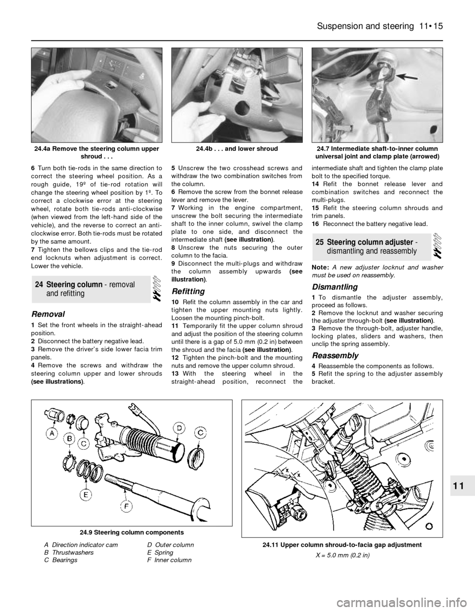
4Remove the screws and withdraw the
steering column upper and lower shrouds
(see illustrations). 5Unscrew the two crosshead screws and
withdraw the two combination switches from
the column.
6Remove the screw from the bonnet release
lever and remove the lever.
7Working in the engine compartment,
unscrew the bolt securing the intermediate
shaft to the inner column, swivel the clamp
plate to one side, and disconnect the
intermediate shaft (see illustration).
8Unscrew the nuts securing the outer
column to the facia.
9Disconnect the multi-plugs and withdraw
the column assembly upwards (see
illustration).
Refitting
10Refit the column assembly in the car and
tighten the upper mounting nuts lightly.
Loosen the mounting pinch-bolt.
11Temporarily fit the upper column shroud
and adjust the position of the steering column
until there is a gap of 5.0 mm (0.2 in) between
the shroud and the facia (see illustration).
12Tighten the pinch-bolt and the mounting
nuts and remove the upper column shroud.
13With the steering wheel in the
straight-ahead position, reconnect theintermediate shaft and tighten the clamp plate
bolt to the specified torque.
14Refit the bonnet release lever and
combination switches and reconnect the
multi-plugs.
15Refit the steering column shrouds and
trim panels.
16Reconnect the battery negative lead.
Note: A new adjuster locknut and washer
must be used on reassembly.
Dismantling
1To dismantle the adjuster assembly,
proceed as follows.
2Remove the locknut and washer securing
the adjuster through-bolt (see illustration).
3Remove the through-bolt, adjuster handle,
locking plates, sliders and washers, then
unclip the spring assembly.
Reassembly
4Reassemble the components as follows.
5Refit the spring to the adjuster assembly
bracket.
25Steering column adjuster -
dismantling and reassembly
24Steering column - removal
and refitting
Suspension and steering 11•15
11
24.4b . . . and lower shroud
24.11 Upper column shroud-to-facia gap adjustment
X = 5.0 mm (0.2 in)
24.9 Steering column components
A Direction indicator cam
B Thrustwashers
C BearingsD Outer column
E Spring
F Inner column
24.7 Intermediate shaft-to-inner column
universal joint and clamp plate (arrowed)24.4a Remove the steering column upper
shroud . . .
Page 16 of 20

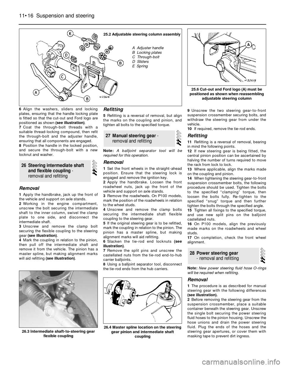
6Align the washers, sliders and locking
plates, ensuring that the handle locking plate
is fitted so that the cut-out and Ford logo are
positioned as shown (see illustration).
7Coat the through-bolt threads with a
suitable thread-locking compound, then refit
the through-bolt and the adjuster handle,
ensuring that all components are engaged.
8Position the handle in the locked position,
and secure the through-bolt with a new
locknut and washer.
Removal
1Apply the handbrake, jack up the front of
the vehicle and support on axle stands.
2Working in the engine compartment,
unscrew the bolt securing the intermediate
shaft to the inner column, swivel the clamp
plate to one side, and disconnect the
intermediate shaft.
3Unscrew and remove the clamp bolt
securing the flexible coupling to the steering
gear (see illustration).
4Mark the coupling in relation to the pinion,
then pull off the intermediate shaft and
remove it from the vehicle. The pinion has a
master spline, but making alignment marks
will aid refitting (see illustration).
Refitting
5Refitting is a reversal of removal, but align
the marks on the coupling and pinion, and
tighten all bolts to the specified torque.
Note: A balljoint separator tool will be
required for this operation.
Removal
1Set the front wheels in the straight-ahead
position. Ensure that the steering lock is
engaged and remove the ignition key.
2Apply the handbrake. Loosen the front
roadwheel nuts, jack up the front of the
vehicle and support on axle stands.
3Remove the roadwheels. On P100 models,
mark the position of the roadwheels in relation
to the wheel studs.
4Unscrew and remove the clamp bolts
securing the intermediate shaft flexible
coupling to the steering gear.
5If the original steering gear is to be refitted,
mark the coupling in relation to the pinion. The
pinion has a master spline, but making
alignment marks will aid refitting.
6Slacken the tie-rod end locknuts (see
illustration).
7Remove the split pins and unscrew the
castellated nuts from the tie-rod end-to-hub
carrier balljoints.
8Using a balljoint separator tool, disconnect
the tie-rod ends from the hub carriers.9Unscrew the two steering gear-to-front
suspension crossmember securing bolts, and
withdraw the steering gear from under the
vehicle.
10If required, remove the tie-rod ends.
Refitting
11Refitting is a reversal of removal, bearing
in mind the following points.
12If new steering gear is being fitted, the
central pinion position can be ascertained by
halving the number of turns required to move
the rack from lock to lock.
13Where applicable, align the marks made
on the coupling and pinion.
14When tightening the steering gear-to-front
suspension crossmember bolts, the following
procedure should be used. Tighten the bolts
to the specified “clamping” torque, then
loosen the bolts fully. Re-tighten to the
specified “snug” torque and then further
tighten the bolts through the specified angle.
15Tighten all fixings to the specified torque,
and use new split pins on the balljoint
castellated nuts.
16On P100 models, align the previously
made marks on the roadwheels and wheel
studs.
17On completion, check the front wheel
alignment.
Note: New power steering fluid hose O-rings
will be required when refitting.
Removal
1The procedure is as described for manual
steering gear with the following differences
(see illustration).
2Before removing the steering gear from the
suspension crossmember, place a suitable
container beneath the steering gear. Unscrew
the single bolt securing the power steering
fluid hoses to the pinion housing. Unscrew the
hose unions and drain the power steering
fluid. Plug the ends of the hoses and the
steering gear apertures, or cover them with
masking tape to prevent dirt ingress.
28Power steering gear
- removal and refitting
27Manual steering gear -
removaland refitting
26Steering intermediate shaft
and flexible coupling -
removal and refitting
11•16Suspension and steering
25.6 Cut-out and Ford logo (A) must be
positioned as shown when reassembling
adjustable steering column
26.4 Master spline location on the steering
gear pinion and intermediate shaft
coupling26.3 Intermediate shaft-to-steering gear
flexible coupling
25.2 Adjustable steering column assembly
A Adjuster handle
B Locking plates
C Through-bolt
D Sliders
E Spring