jacking FORD SIERRA 1992 2.G Bodywork And Fittings Workshop Manual
[x] Cancel search | Manufacturer: FORD, Model Year: 1992, Model line: SIERRA, Model: FORD SIERRA 1992 2.GPages: 22, PDF Size: 1.2 MB
Page 4 of 22

compatible with the type of plastic used. At one
time the use of a universal paint was not
possible owing to the complex range of plastics
encountered in body component applications.
Standard paints, generally speaking, will not
bond to plastic or rubber satisfactorily.
However, it is now possible to obtain a plastic
body parts finishing kit which consists of a pre-
primer treatment, a primer and coloured top
coat. Full instructions are normally supplied with
a kit, but basically the method of use is to first
apply the pre-primer to the component
concerned and allow it to dry for up to 30
minutes. Then the primer is applied and left to
dry for about an hour before finally applying the
special coloured top coat. The result is a
correctly coloured component where the paint
will flex with the plastic or rubber, a property
that standard paint does not normally possess.
Where serious damage has occurred or large
areas need renewal due to neglect, it means
certainly that completely new sections or panels
will need welding in and this is best left to
professionals. If the damage is due to impact, it
will also be necessary to completely check the
alignment of the bodyshell structure. Due to the
principle of construction, the strength and shape
of the whole car can be affected by damage to
one part. In such instances the services of a
Ford agent with specialist checking jigs are
essential. If a body is left misaligned, it is first of
all dangerous as the car will not handle properly,
and secondly uneven stresses will be imposed
on the steering, engine and transmission,
causing abnormal wear or complete failure. Tyre
wear may also be excessive.
Removal
1Support the bonnet in its open position,
and place protective covers (old rags or
cardboard) beneath the corners of the bonnet,
and over the front wings to prevent damage to
the paintwork.
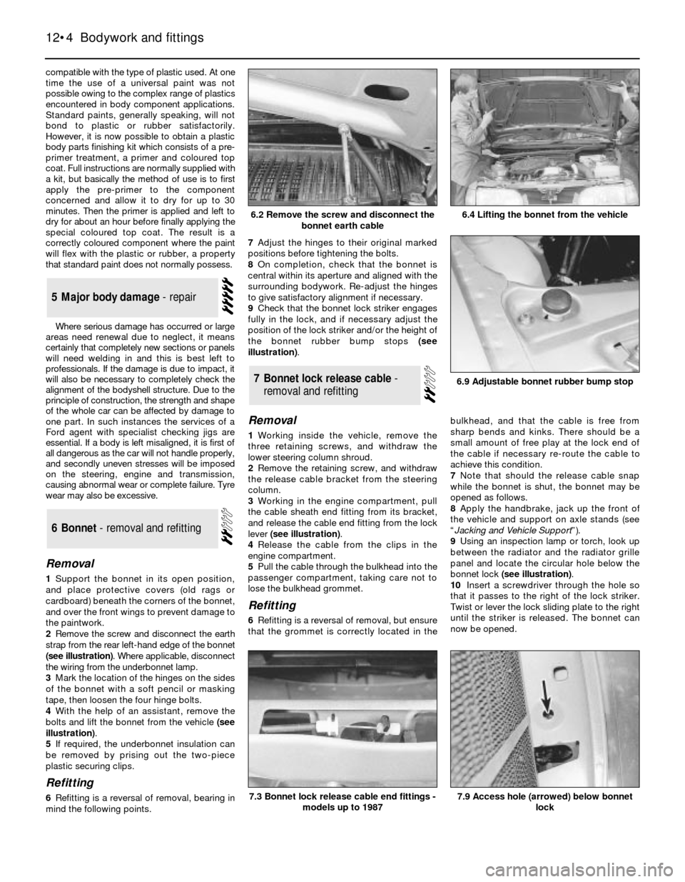
2Remove the screw and disconnect the earth
strap from the rear left-hand edge of the bonnet
(see illustration). Where applicable, disconnect
the wiring from the underbonnet lamp.
3Mark the location of the hinges on the sides
of the bonnet with a soft pencil or masking
tape, then loosen the four hinge bolts.
4With the help of an assistant, remove the
bolts and lift the bonnet from the vehicle (see
illustration).
5If required, the underbonnet insulation can
be removed by prising out the two-piece
plastic securing clips.
Refitting
6Refitting is a reversal of removal, bearing in
mind the following points.7Adjust the hinges to their original marked
positions before tightening the bolts.
8On completion, check that the bonnet is
central within its aperture and aligned with the
surrounding bodywork. Re-adjust the hinges
to give satisfactory alignment if necessary.
9Check that the bonnet lock striker engages
fully in the lock, and if necessary adjust the
position of the lock striker and/or the height of
the bonnet rubber bump stops (see
illustration).
Removal
1Working inside the vehicle, remove the
three retaining screws, and withdraw the
lower steering column shroud.
2Remove the retaining screw, and withdraw
the release cable bracket from the steering
column.
3Working in the engine compartment, pull
the cable sheath end fitting from its bracket,
and release the cable end fitting from the lock
lever (see illustration).
4Release the cable from the clips in the
engine compartment.
5Pull the cable through the bulkhead into the
passenger compartment, taking care not to
lose the bulkhead grommet.
Refitting
6Refitting is a reversal of removal, but ensure
that the grommet is correctly located in thebulkhead, and that the cable is free from
sharp bends and kinks. There should be a
small amount of free play at the lock end of
the cable if necessary re-route the cable to
achieve this condition.
7Note that should the release cable snap
while the bonnet is shut, the bonnet may be
opened as follows.
8Apply the handbrake, jack up the front of
the vehicle and support on axle stands (see
“
Jacking and Vehicle Support”).
9Using an inspection lamp or torch, look up
between the radiator and the radiator grille
panel and locate the circular hole below the
bonnet lock (see illustration).
10Insert a screwdriver through the hole so
that it passes to the right of the lock striker.
Twist or lever the lock sliding plate to the right
until the striker is released. The bonnet can
now be opened.
7Bonnet lock release cable -
removal and refitting
6Bonnet - removal and refitting
5Major body damage - repair
12•4Bodywork and fittings
6.2 Remove the screw and disconnect the
bonnet earth cable
6.9 Adjustable bonnet rubber bump stop
7.9 Access hole (arrowed) below bonnet
lock7.3 Bonnet lock release cable end fittings -
models up to 1987
6.4 Lifting the bonnet from the vehicle
Page 18 of 22

20On models with an adjustable steering
column, fully extend and lower the steering
column before attempting to remove any of
the panels on the driver’s side.
21The steering column shrouds are secured
by six screws - five through the lower shroud,
and one through the upper shroud.
22If necessary, remove the centre console.
23The driver’s side lower facia panel is
secured by five screws.
24The passenger’s side lower facia panel is
secured by eight screws.
25On models with an alarm, the alarm warning
light must be disconnected and removed before
removing the upper facia panel.
Models up to 1990
Full length console
1Where applicable, prise the electric window
switches from the front upper console panel
and disconnect the wiring.
2Remove the three securing screws from the
front upper console panel, then withdraw the
panel over the gear selector lever, at the same
time releasing the rubber gaiter where
applicable.
3On “high specification” models, where
applicable prise the electric window switches
from the rear upper console panel and
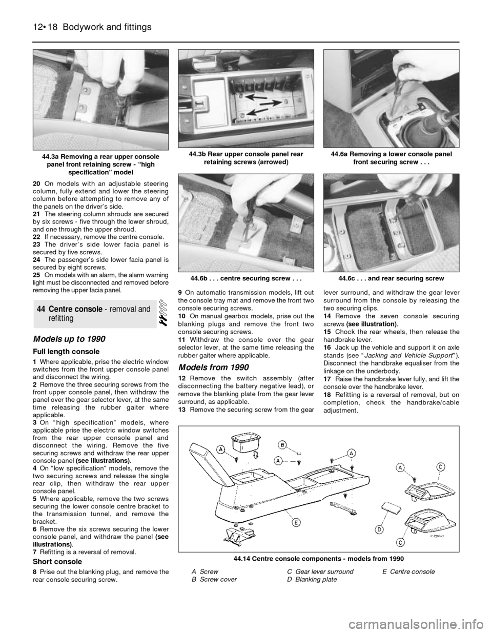
disconnect the wiring. Remove the five
securing screws and withdraw the rear upper
console panel (see illustrations).
4On “low specification” models, remove the
two securing screws and release the single
rear clip, then withdraw the rear upper
console panel.
5Where applicable, remove the two screws
securing the lower console centre bracket to
the transmission tunnel, and remove the
bracket.
6Remove the six screws securing the lower
console panel, and withdraw the panel (see
illustrations).
7Refitting is a reversal of removal.
Short console
8Prise out the blanking plug, and remove the
rear console securing screw.9On automatic transmission models, lift out
the console tray mat and remove the front two
console securing screws.
10On manual gearbox models, prise out the
blanking plugs and remove the front two
console securing screws.
11Withdraw the console over the gear
selector lever, at the same time releasing the
rubber gaiter where applicable.
Models from 1990
12Remove the switch assembly (after
disconnecting the battery negative lead), or
remove the blanking plate from the gear lever
surround, as applicable.
13Remove the securing screw from the gearlever surround, and withdraw the gear lever
surround from the console by releasing the
two securing clips.
14Remove the seven console securing
screws (see illustration).
15Chock the rear wheels, then release the
handbrake lever.
16Jack up the vehicle and support it on axle
stands (see “Jacking and Vehicle Support”).
Disconnect the handbrake equaliser from the
linkage on the underbody.
17Raise the handbrake lever fully, and lift the
console over the handbrake lever.
18Refitting is a reversal of removal, but on
completion, check the handbrake/cable
adjustment.
44Centre console - removal and
refitting
12•18Bodywork and fittings
44.3b Rear upper console panel rear
retaining screws (arrowed)
44.6b . . . centre securing screw . . .
44.14 Centre console components - models from 1990
A Screw
B Screw coverC Gear lever surround
D Blanking plateE Centre console
44.6c . . . and rear securing screw
44.6a Removing a lower console panel
front securing screw . . .44.3a Removing a rear upper console
panel front retaining screw - “high
specification” model