clock setting FORD SIERRA 1992 2.G Braking System Workshop Manual
[x] Cancel search | Manufacturer: FORD, Model Year: 1992, Model line: SIERRA, Model: FORD SIERRA 1992 2.GPages: 22, PDF Size: 1.11 MB
Page 13 of 22

3Remove the wheel cylinder.
4Remove the driveshaft but do not refit the
securing bolts to the backplate.
5Remove the backplate.
6If required, prise out the handbrake stop
button.
7Refitting is a reversal of removal.
P 100 models
Note: When refitting the backplate, a new rear
hub nut and driveshaft O-ring must be used.
8Proceed as described in paragraphs 1 to 3
inclusive.
9Remove the driveshaft.
10Relieve the staking on the rear hub nut,
and using a 50 mm socket and a suitable
extension bar, unscrew the nut. Note that the
nut is extremely tight.
11Pull off the hub.
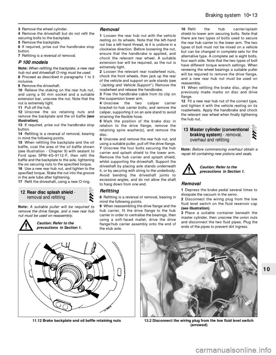
12Unscrew the six retaining nuts and
remove the backplate and the oil baffle (see
illustration).
13If required, prise out the handbrake stop
button.
14Refitting is a reversal of removal, bearing
in mind the following points.
15When refitting the backplate and the oil
baffle, coat the area of the oil baffle shown
(see illustration - Chapter 9) with sealant to
Ford spec SPM-4G-9112-F, then refit the
baffle and the backplate to the axle, tightening
the six securing nuts to the specified torque.
16Use a new rear hub nut, and tighten to the
specified torque. Stake the nut into the groove
in the axle tube after tightening.
17Refit the driveshaft, using a new O-ring.
Note: A suitable puller will be required to
remove the drive flange, and a new rear hub
nut must be used on reassembly.
Removal
1Loosen the rear hub nut with the vehicle
resting on its wheels. Note that the left-hand
nut has a left-hand thread, ie it is undone in a
clockwise direction. Before loosening the nut,
ensure that the handbrake is applied, and
chock the relevant rear wheel. A suitable
extension bar will be required, as the nut is
extremely tight.
2Loosen the relevant rear roadwheel nuts,
chock the front wheels, then jack up the rear
of the vehicle and support on axle stands (see
“Jacking and Vehicle Support”).Remove the
roadwheel and release the handbrake.
3Free the handbrake cable from its clip on
the suspension lower arm.
4Unscrew the two caliper carrier
bracket-to-hub carrier bolts, and remove the
caliper, supporting it on an axle stand to avoid
straining the flexible hose.
5Mark the position of the brake disc in
relation to the drive flange, remove the
retaining spire washer(s), and remove the
disc.
6Unscrew and remove the rear hub nut, and
using a suitable puller, pull off the drive flange.
7Unscrew the four bolts securing the hub
carrier and splash shield to the lower arm.
Remove the hub carrier and splash shield,
whilst supporting the driveshaft. Support the
driveshaft by placing axle stands underneath
it, or by securing with string to the underbody.
Avoid bending the driveshaft joints to
excessive angles, and do not allow the shaft
to hang down from one end.
Refitting
8Refitting is a reversal of removal, bearing in
mind the following points.
9When reassembling the drive flange and the
hub carrier, fit the drive flange to the hub
carrier in order to centralise the bearings, then
using a soft-faced mallet, drive the drive
flange/hub carrier assembly onto the end of
the stub axle.10Refit the hub carrier/splash
shield-to-lower arm securing bolts. Note that
there are two types of bolts used to secure
the rear hub carrier to the lower arm. The two
types of bolt must not be mixed on a vehicle
but can be changed in complete sets for the
alternative type. A complete set is eight bolts,
four each side. Note that the two types of bolt
have different torque wrench settings. When
renewing the wheel bearings a suitable puller
will be required to remove the drive flange,
and a new rear hub nut must be used on
reassembly.
11When refitting the brake disc, align the
previously made marks on disc and drive
flange.
12Fit a new rear hub nut of the correct type,
and tighten it with the vehicle resting on its
roadwheels. Apply the handbrake and chock
the relevant rear wheel when finally tightening
the hub nut.
Note: Before commencing overhaul obtain a
repair kit containing new pistons and seals.
Removal
1Depress the brake pedal several times to
dissipate the vacuum in the servo.
2Disconnect the wiring plug from the low
fluid level switch on the fluid reservoir cap
(see illustration).
3Place a suitable container beneath the
master cylinder, then unscrew the union nuts
and disconnect the two fluid pipes. Plug the
ends of the pipes to prevent dirt ingress.
13Master cylinder (conventional
braking system) - removal,
overhaul and refitting
12Rear disc splash shield -
removal and refitting
Braking system 10•13
10
13.2 Disconnect the wiring plug from the low fluid level switch
(arrowed)11.12 Brake backplate and oil baffle retaining nuts
Caution: Refer to the
precautions in Section 1.
Caution: Refer to the
precautions in Section 1.