stop start FORD SIERRA 1992 2.G Braking System Workshop Manual
[x] Cancel search | Manufacturer: FORD, Model Year: 1992, Model line: SIERRA, Model: FORD SIERRA 1992 2.GPages: 22, PDF Size: 1.11 MB
Page 3 of 22

8Open the bleed screw half a turn and have
your assistant depress the brake pedal slowly
to the floor and then, after the bleed screw is
retightened, quickly remove his foot to allow
the pedal to return unimpeded. Repeat the
procedure.
9Observe the submerged end of the tube in
the jar. When air bubbles cease to appear,
tighten the bleed screw when the pedal is
being held fully down by your assistant.
10Top-up the fluid reservoir. It must be kept
topped up throughout the bleeding
operations. If the connecting holes to the
master cylinder are exposed at any time due
to low fluid level, then air will be drawn into
the system and work will have to start all over
again.
11Assuming that the complete system is
being bled, the procedure described in the
preceding paragraphs should be repeated on
the front right-hand caliper followed by the
rear right-hand and left-hand wheel cylinders.
12On completion, remove the bleed tube,
and discard the fluid which has been bled
from the system unless it is required for bleed
jar purposes. Never re-use old fluid.
13On completion of bleeding, top-up the
fluid level in the reservoir. Check the action of
the brake pedal, which should be firm and free
from any “sponginess” which would indicate
that air is still present in the system.
With one-way valve
14There are a number of one-man brake
bleeding kits currently available from motor
accessory shops. It is recommended that one
of these kits should be used whenever
possible, as they greatly simplify the bleeding
operation and also reduce the risk of expelled
air or fluid being drawn back into the system.
15Proceed as described in paragraphs 5
and 6.
16Open the bleed screw half a turn then
depress the brake pedal to the floor and
slowly release it. The one-way valve in the
bleeder device will prevent expelled air from
returning to the system at the completion of
each stroke. Repeat this operation until clear
hydraulic fluid, free from air bubbles, can be
seen coming through the tube. Tighten the
bleed screw.
17Proceed as shown in paragraphs 11 to 13.
With pressure bleeding kit
18These too are available from motor
accessory shops and are usually operated by
air pressure from the spare tyre.
19By connecting a pressurised container to
the master cylinder fluid reservoir, bleeding is
then carried out by simply opening each bleed
screw in turn and allowing the fluid to run out,
rather like turning on a tap, until no air bubbles
are visible in the fluid being expelled.
20Using this system, the large reserve of
fluid provides a safeguard against air being
drawn into the master cylinder during the
bleeding operations.21This method is particularly effective when
bleeding “difficult” systems or when bleeding
the entire system at time of routine fluid
renewal.
22Begin bleeding with reference to
paragraphs 5 and 6 and proceed as described
in paragraphs 11 to 13.
1Keep the fluid reservoir replenished
throughout the bleeding operations.
2Remove the dust cap where fitted, and
clean around the bleed screw on the left-hand
front caliper. Fit a bleed tube to the screw and
immerse the open end in a jar containing
clean hydraulic fluid.
3Open the bleed valve one full turn and have
an assistant depress the brake pedal fully and
hold it down.
4Close the bleed valve and release the brake
pedal. Repeat the procedure until fluid ejected
from the end of the tube is free from air
bubbles.
5Repeat the operations on the right-hand
front caliper.
6Fit the bleed tube to the left-hand rear
caliper and open the bleed valve one full turn.
7Have an assistant depress the brake pedal
fully and hold it down.
8Switch on the ignition to position ll.
9Allow the fluid to bleed from the tube for at
least 15 seconds, when the fluid should be
free from air bubbles.
10Close the bleed valve.
11Release the brake pedal and wait for the
hydraulic pump to stop.
12Fit the bleed tube to the right-hand rear
caliper and open the bleed valve one full turn.
13Have your assistant depress the brake
pedal through half its travel and hold it there.
Allow the fluid to bleed from the tube for at
least 15 seconds, when the fluid should be
free from air bubbles.
14Close the bleed valve.
15Release the brake pedal and wait for the
hydraulic pump to stop then switch off the
ignition.
16Top-up the reservoir with clean fluid.
17When the hydraulic system is being bled
for the purpose of renewing the fluid at the
specified interval, as each caliper is bled,
operate the brake pedal continuously until
clean fluid is seen to enter the jar.
18When the hydraulic pump is running its
note will be heard to change once fluid has
purged through it. Do not allow the pump torun continuously for more than two minutes. If
it does run for a longer period, switch off the
ignition and allow the motor to cool for ten
minutes.
19On completion, discard the fluid which
has been bled from the system unless it is
required for bleed jar purposes. Never re-use
old fluid.
20Check the action of the brake pedal,
which should be firm and free from any
“sponginess”, which would indicate that air is
still present in the system.
Front disc pads
1The disc pad friction material can be
inspected for wear without removing the
roadwheels. Working beneath the vehicle,
insert a mirror between the caliper and the
roadwheel and check that the friction material
thickness is not less than the minimum given
in the Specifications.
2If any one of the pads has worn below the
specified limit, the front pads must be
renewed as an axle set (4 pads).
3To renew the pads, slacken the front
roadwheel nuts, apply the handbrake, then
jack up the front of the vehicle and support on
axle stands (see “Jacking and Vehicle
Support”). Remove the roadwheels. On P100
models, mark the position of the roadwheels
in relation to the wheel studs before removal.
4Proceed as follows according to model:
Girling caliper (1.3 and early 1.6 litre
models)
5Where applicable, disconnect the wiring to
the disc pad wear sensor.
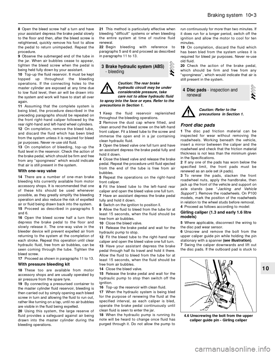
6Unscrew and remove the bolt from the
upper caliper guide pin while holding the pin
stationary with a spanner (see illustration).
7Swing the caliper downwards and lift out
the disc pads. If the outboard pad is stuck to
4Disc pads -inspectionand
renewal
3Brake hydraulic system (ABS)
- bleeding
Braking system 10•3
10
4.6 Unscrewing the bolt from the upper
caliper guide pin - Girling caliper
Caution: Refer to the
precautions in Section 1.
Caution: The rear brake
hydraulic circuit may be under
considerable pressure, take
care not to allow hydraulic fluid
to spray into the face or eyes. Refer to the
precautions in Section 1.
Page 21 of 22

Note: Where fitted, the adjuster locking pin
must be renewed on completion of
adjustment.
Conventional braking system
(except P100 models)
1The handbrake cable is normally
self-adjusting in use, however adjustment
may be required to compensate for cable
stretch over a long period, and is also
necessary after fitting a new cable.
2Chock the front wheels, jack up the rear of
the vehicle and support on axle stands (see
“Jacking and Vehicle Support”).Release the
handbrake.
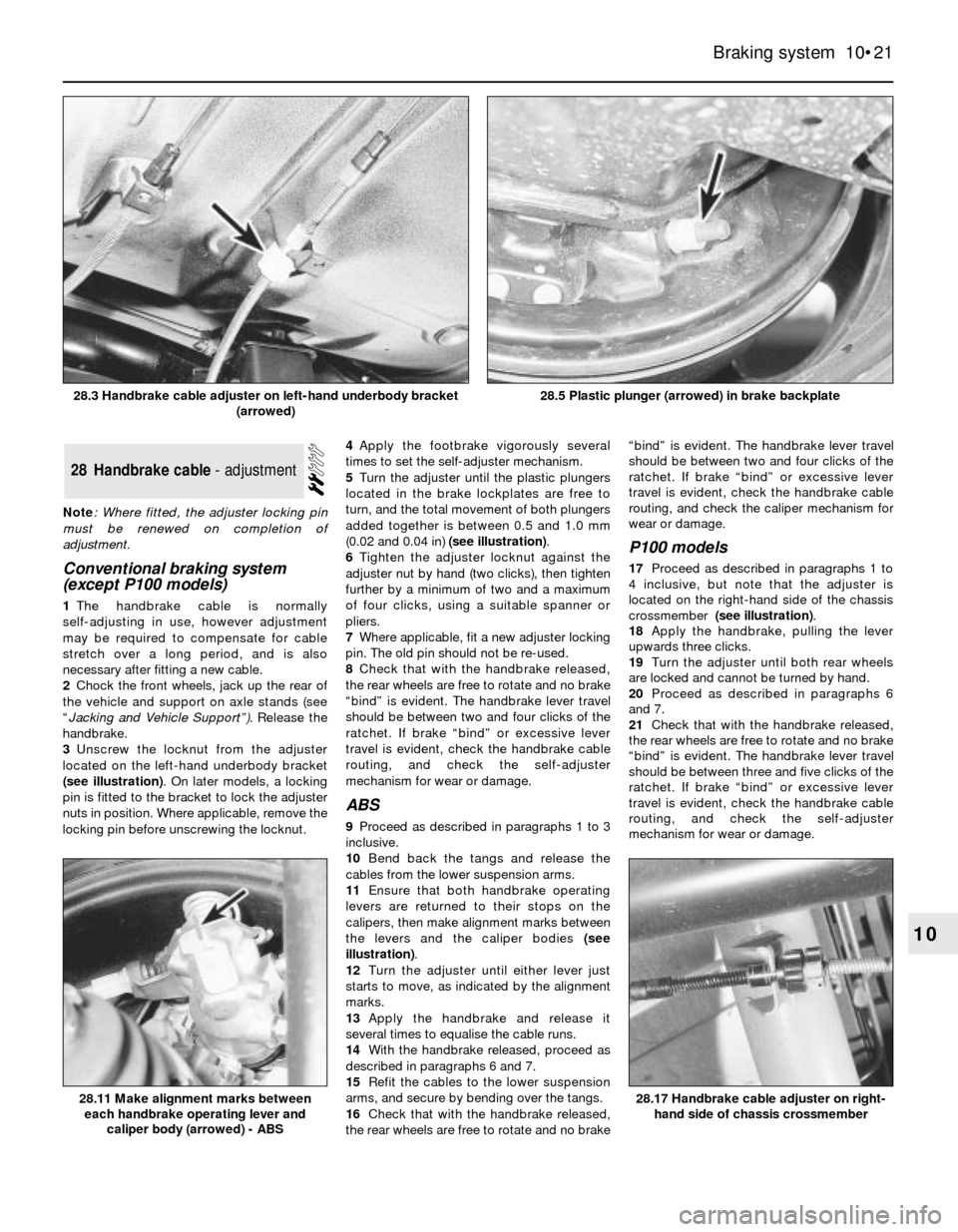
3Unscrew the locknut from the adjuster
located on the left-hand underbody bracket
(see illustration). On later models, a locking
pin is fitted to the bracket to lock the adjuster
nuts in position. Where applicable, remove the
locking pin before unscrewing the locknut.4Apply the footbrake vigorously several
times to set the self-adjuster mechanism.
5Turn the adjuster until the plastic plungers
located in the brake lockplates are free to
turn, and the total movement of both plungers
added together is between 0.5 and 1.0 mm
(0.02 and 0.04 in) (see illustration).
6Tighten the adjuster locknut against the
adjuster nut by hand (two clicks), then tighten
further by a minimum of two and a maximum
of four clicks, using a suitable spanner or
pliers.
7Where applicable, fit a new adjuster locking
pin. The old pin should not be re-used.
8Check that with the handbrake released,
the rear wheels are free to rotate and no brake
“bind” is evident. The handbrake lever travel
should be between two and four clicks of the
ratchet. If brake “bind” or excessive lever
travel is evident, check the handbrake cable
routing, and check the self-adjuster
mechanism for wear or damage.
ABS
9Proceed as described in paragraphs 1 to 3
inclusive.
10Bend back the tangs and release the
cables from the lower suspension arms.
11Ensure that both handbrake operating
levers are returned to their stops on the
calipers, then make alignment marks between
the levers and the caliper bodies (see
illustration).
12Turn the adjuster until either lever just
starts to move, as indicated by the alignment
marks.
13Apply the handbrake and release it
several times to equalise the cable runs.
14With the handbrake released, proceed as
described in paragraphs 6 and 7.
15Refit the cables to the lower suspension
arms, and secure by bending over the tangs.
16Check that with the handbrake released,
the rear wheels are free to rotate and no brake“bind” is evident. The handbrake lever travel
should be between two and four clicks of the
ratchet. If brake “bind” or excessive lever
travel is evident, check the handbrake cable
routing, and check the caliper mechanism for
wear or damage.
P100 models
17Proceed as described in paragraphs 1 to
4 inclusive, but note that the adjuster is
located on the right-hand side of the chassis
crossmember (see illustration).
18Apply the handbrake, pulling the lever
upwards three clicks.
19Turn the adjuster until both rear wheels
are locked and cannot be turned by hand.
20Proceed as described in paragraphs 6
and 7.
21Check that with the handbrake released,
the rear wheels are free to rotate and no brake
“bind” is evident. The handbrake lever travel
should be between three and five clicks of the
ratchet. If brake “bind” or excessive lever
travel is evident, check the handbrake cable
routing, and check the self-adjuster
mechanism for wear or damage.
28Handbrake cable - adjustment
Braking system 10•21
10
28.5 Plastic plunger (arrowed) in brake backplate
28.17 Handbrake cable adjuster on right-
hand side of chassis crossmember28.11 Make alignment marks between
each handbrake operating lever and
caliper body (arrowed) - ABS
28.3 Handbrake cable adjuster on left-hand underbody bracket
(arrowed)