AUX FORD SIERRA 1992 2.G DOHC Engine Workshop Manual
[x] Cancel search | Manufacturer: FORD, Model Year: 1992, Model line: SIERRA, Model: FORD SIERRA 1992 2.GPages: 18, PDF Size: 0.9 MB
Page 13 of 18

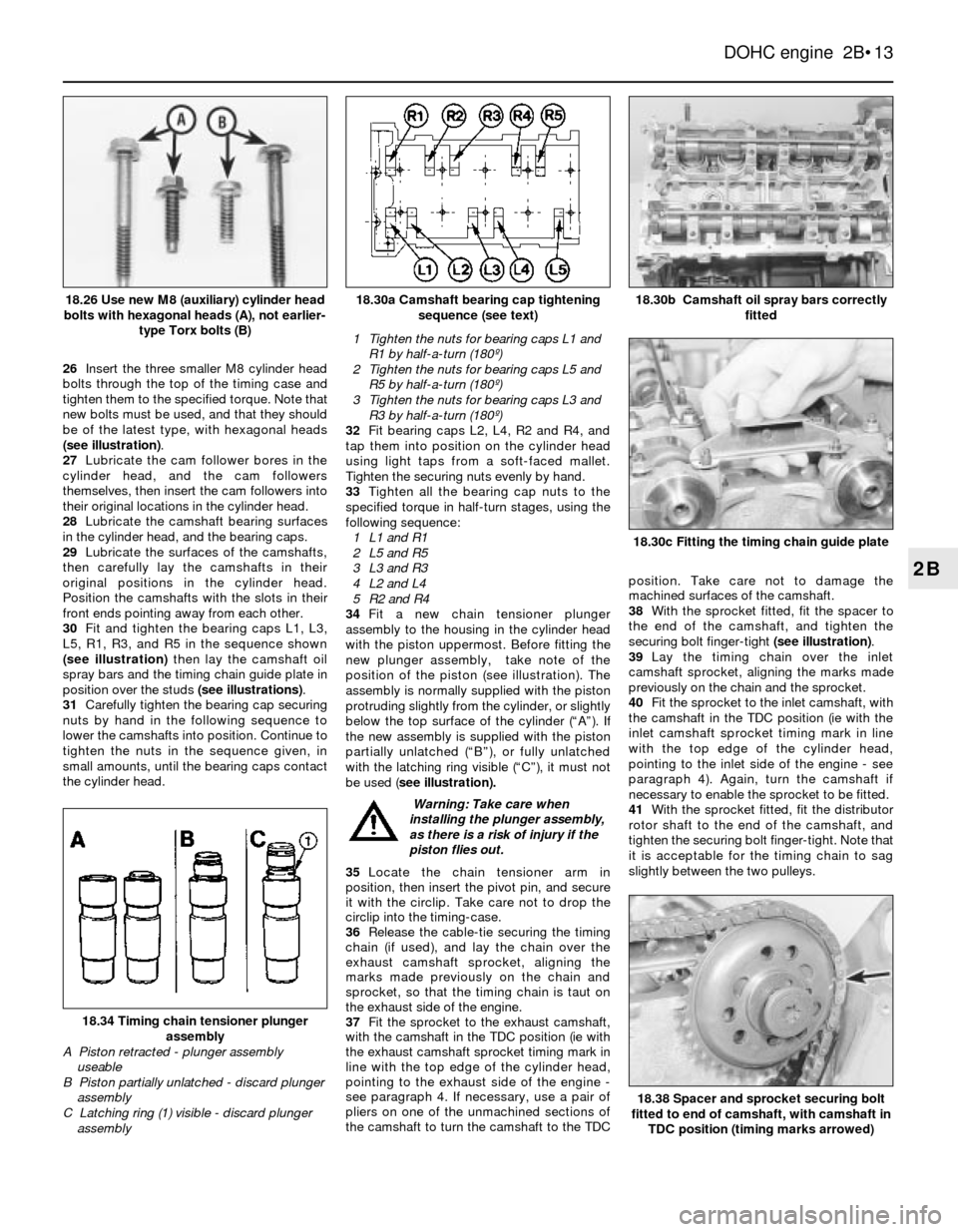
26Insert the three smaller M8 cylinder head
bolts through the top of the timing case and
tighten them to the specified torque. Note that
new bolts must be used, and that they should
be of the latest type, with hexagonal heads
(see illustration).
27Lubricate the cam follower bores in the
cylinder head, and the cam followers
themselves, then insert the cam followers into
their original locations in the cylinder head.
28Lubricate the camshaft bearing surfaces
in the cylinder head, and the bearing caps.
29Lubricate the surfaces of the camshafts,
then carefully lay the camshafts in their
original positions in the cylinder head.
Position the camshafts with the slots in their
front ends pointing away from each other.
30Fit and tighten the bearing caps L1, L3,
L5, R1, R3, and R5 in the sequence shown
(see illustration)then lay the camshaft oil
spray bars and the timing chain guide plate in
position over the studs (see illustrations).
31Carefully tighten the bearing cap securing
nuts by hand in the following sequence to
lower the camshafts into position. Continue to
tighten the nuts in the sequence given, in
small amounts, until the bearing caps contact
the cylinder head.1Tighten the nuts for bearing caps L1 and
R1 by half-a-turn (180º)
2Tighten the nuts for bearing caps L5 and
R5 by half-a-turn (180º)
3Tighten the nuts for bearing caps L3 and
R3 by half-a-turn (180º)
32Fit bearing caps L2, L4, R2 and R4, and
tap them into position on the cylinder head
using light taps from a soft-faced mallet.
Tighten the securing nuts evenly by hand.
33Tighten all the bearing cap nuts to the
specified torque in half-turn stages, using the
following sequence:
1L1 and R1
2L5 and R5
3L3 and R3
4L2 and L4
5R2 and R4
34Fit a newchain tensioner plunger
assembly to the housing in the cylinder head
with the piston uppermost. Before fitting the
new plunger assembly, take note of the
position of the piston(see illustration). The
assembly is normally supplied with the piston
protruding slightly from the cylinder, or slightly
below the top surface of the cylinder (“A”). If
the new assembly is supplied with the piston
partially unlatched (“B”), or fully unlatched
with the latching ring visible (“C”), it must not
be used (see illustration).
35Locate the chain tensioner arm in
position, then insert the pivot pin, and secure
it with the circlip. Take care not to drop the
circlip into the timing-case.
36Release the cable-tie securing the timing
chain (if used), and lay the chain over the
exhaust camshaft sprocket, aligning the
marks made previously on the chain and
sprocket, so that the timing chain is taut on
the exhaust side of the engine.
37Fit the sprocket to the exhaust camshaft,
with the camshaft in the TDC position (ie with
the exhaust camshaft sprocket timing mark in
line with the top edge of the cylinder head,
pointing to the exhaust side of the engine -
see paragraph 4. If necessary, use a pair of
pliers on one of the unmachined sections of
the camshaft to turn the camshaft to the TDCposition. Take care not to damage the
machined surfaces of the camshaft.
38With the sprocket fitted, fit the spacer to
the end of the camshaft, and tighten the
securing bolt finger-tight (see illustration).
39Lay the timing chain over the inlet
camshaft sprocket, aligning the marks made
previously on the chain and the sprocket.
40Fit the sprocket to the inlet camshaft, with
the camshaft in the TDC position (ie with the
inlet camshaft sprocket timing mark in line
with the top edge of the cylinder head,
pointing to the inlet side of the engine - see
paragraph 4). Again, turn the camshaft if
necessary to enable the sprocket to be fitted.
41With the sprocket fitted, fit the distributor
rotor shaft to the end of the camshaft, and
tighten the securing bolt finger-tight. Note that
it is acceptable for the timing chain to sag
slightly between the two pulleys.
DOHC engine 2B•13
2B
18.30b Camshaft oil spray bars correctly
fitted
18.38 Spacer and sprocket securing bolt
fitted to end of camshaft, with camshaft in
TDC position (timing marks arrowed)
18.34 Timing chain tensioner plunger
assembly
A Piston retracted - plunger assembly
useable
B Piston partially unlatched - discard plunger
assembly
C Latching ring (1) visible - discard plunger
assembly
18.30c Fitting the timing chain guide plate
18.30a Camshaft bearing cap tightening
sequence (see text)18.26 Use new M8 (auxiliary) cylinder head
bolts with hexagonal heads (A), not earlier-
type Torx bolts (B)
Warning: Take care when
installing the plunger assembly,
as there is a risk of injury if the
piston flies out.