Valve FORD SIERRA 1992 2.G DOHC Engine Workshop Manual
[x] Cancel search | Manufacturer: FORD, Model Year: 1992, Model line: SIERRA, Model: FORD SIERRA 1992 2.GPages: 18, PDF Size: 0.9 MB
Page 2 of 18

Crankshaft
Endfloat . . . . . . . . . . . . . . . . . . . . . . . . . . . . . . . . . . . . . . . . . . . . . . . . . .0.090 to 0.300 mm (0.004 to 0.012 in)
Main bearing running clearance . . . . . . . . . . . . . . . . . . . . . . . . . . . . . . .0.011 to 0.048 mm
Main bearing journal diameter:
Standard (yellow) . . . . . . . . . . . . . . . . . . . . . . . . . . . . . . . . . . . . . . . .54.980 to 54.990 mm
Standard (red) . . . . . . . . . . . . . . . . . . . . . . . . . . . . . . . . . . . . . . . . . . .54.990 to 55.000 mm
Undersize 0.25 (green) . . . . . . . . . . . . . . . . . . . . . . . . . . . . . . . . . . . .54.730 to 54.750 mm
Main bearing thrustwasher thickness:
Standard . . . . . . . . . . . . . . . . . . . . . . . . . . . . . . . . . . . . . . . . . . . . . . .2.301 to 2.351 mm (0.090 to 0.093 in)
Oversize 0.38 (yellow) . . . . . . . . . . . . . . . . . . . . . . . . . . . . . . . . . . . . .2.491 to 2.541 mm (0.098 to 0.100 in)
Big-end bearing running clearance . . . . . . . . . . . . . . . . . . . . . . . . . . . .0.006 to 0.060 mm
Big-end bearing journal diameter:
Standard . . . . . . . . . . . . . . . . . . . . . . . . . . . . . . . . . . . . . . . . . . . . . . .50.890 to 50.910 mm
Undersize 0.25 (green) . . . . . . . . . . . . . . . . . . . . . . . . . . . . . . . . . . . .50.640 to 50.660 mm
Pistons and piston rings
Piston diameter:
Standard 1 . . . . . . . . . . . . . . . . . . . . . . . . . . . . . . . . . . . . . . . . . . . . .85.970 to 85.980 mm
Standard 2 . . . . . . . . . . . . . . . . . . . . . . . . . . . . . . . . . . . . . . . . . . . . .85.980 to 85.990 mm
Standard service . . . . . . . . . . . . . . . . . . . . . . . . . . . . . . . . . . . . . . . . .85.980 to 85.990 mm
Oversize 0.15 . . . . . . . . . . . . . . . . . . . . . . . . . . . . . . . . . . . . . . . . . . .86.130 to 86.150 mm
Oversize 0.50 . . . . . . . . . . . . . . . . . . . . . . . . . . . . . . . . . . . . . . . . . . .86.470 to 86.490 mm
Piston ring end gap:
Top . . . . . . . . . . . . . . . . . . . . . . . . . . . . . . . . . . . . . . . . . . . . . . . . . . .0.300 to 0.600 mm (0.012 to 0.024 in)
Centre . . . . . . . . . . . . . . . . . . . . . . . . . . . . . . . . . . . . . . . . . . . . . . . . .0.500 to 0.800 mm (0.020 to 0.032 in)
Bottom (oil control) . . . . . . . . . . . . . . . . . . . . . . . . . . . . . . . . . . . . . . .0.400 to 1.500 mm (0.016 to 0.059 in)
Cylinder head
Valve guide bore . . . . . . . . . . . . . . . . . . . . . . . . . . . . . . . . . . . . . . . . . . .7.063 to 7.094 mm
Camshaft bearing parent bore diameter . . . . . . . . . . . . . . . . . . . . . . . .26.000 to 26.030 mm
Camshafts
Endfloat . . . . . . . . . . . . . . . . . . . . . . . . . . . . . . . . . . . . . . . . . . . . . . . . . .0.020 to 0.260 mm (0.001 to 0.010 in)
Valves
Valve timing:
Carburettor engines:
Inlet opens . . . . . . . . . . . . . . . . . . . . . . . . . . . . . . . . . . . . . . . . . . .13º BTDC
Inlet closes . . . . . . . . . . . . . . . . . . . . . . . . . . . . . . . . . . . . . . . . . . .39º ABDC
Exhaust opens . . . . . . . . . . . . . . . . . . . . . . . . . . . . . . . . . . . . . . . .43º BBDC
Exhaust closes . . . . . . . . . . . . . . . . . . . . . . . . . . . . . . . . . . . . . . . .13º ATDC
Fuel injection engines:
Inlet opens . . . . . . . . . . . . . . . . . . . . . . . . . . . . . . . . . . . . . . . . . . .13º BTDC
Inlet closes . . . . . . . . . . . . . . . . . . . . . . . . . . . . . . . . . . . . . . . . . . .51º ABDC
Exhaust opens . . . . . . . . . . . . . . . . . . . . . . . . . . . . . . . . . . . . . . . .43º BBDC
Exhaust closes . . . . . . . . . . . . . . . . . . . . . . . . . . . . . . . . . . . . . . . .13º ATDC
Valve spring free length:
Inner spring . . . . . . . . . . . . . . . . . . . . . . . . . . . . . . . . . . . . . . . . . . . . .48.200 mm (1.899 in)
Outer spring . . . . . . . . . . . . . . . . . . . . . . . . . . . . . . . . . . . . . . . . . . . .46.800 mm (1.844 in)
Inlet valve stem diameter:
Standard . . . . . . . . . . . . . . . . . . . . . . . . . . . . . . . . . . . . . . . . . . . . . . .7.025 to 7.043 mm
Oversize 0.2 . . . . . . . . . . . . . . . . . . . . . . . . . . . . . . . . . . . . . . . . . . . .7.225 to 7.243 mm
Oversize 0.4 . . . . . . . . . . . . . . . . . . . . . . . . . . . . . . . . . . . . . . . . . . . .7.425 to 7.443 mm
Oversize 0.6 . . . . . . . . . . . . . . . . . . . . . . . . . . . . . . . . . . . . . . . . . . . .7.625 to 7.643 mm
Oversize 0.8 . . . . . . . . . . . . . . . . . . . . . . . . . . . . . . . . . . . . . . . . . . . .7.825 to 7.843 mm
Exhaust valve stem diameter:
Standard . . . . . . . . . . . . . . . . . . . . . . . . . . . . . . . . . . . . . . . . . . . . . . .6.999 to 7.017 mm
Oversize 0.2 . . . . . . . . . . . . . . . . . . . . . . . . . . . . . . . . . . . . . . . . . . . .7.199 to 7.217 mm
Oversize 0.4 . . . . . . . . . . . . . . . . . . . . . . . . . . . . . . . . . . . . . . . . . . . .7.399 to 7.417 mm
Oversize 0.6 . . . . . . . . . . . . . . . . . . . . . . . . . . . . . . . . . . . . . . . . . . . .7.599 to 7.617 mm
Oversize 0.8 . . . . . . . . . . . . . . . . . . . . . . . . . . . . . . . . . . . . . . . . . . . .7.799 to 7.817 mm
Lubrication system
Oil type . . . . . . . . . . . . . . . . . . . . . . . . . . . . . . . . . . . . . . . . . . . . . . . . . .Multigrade engine oil, viscosity range SAE 10W/30 to 20W/50, to API
SG/CD or better
Oil capacity:
With filter . . . . . . . . . . . . . . . . . . . . . . . . . . . . . . . . . . . . . . . . . . . . . . .4.5 litres (7.9 pints)
Without filter . . . . . . . . . . . . . . . . . . . . . . . . . . . . . . . . . . . . . . . . . . . .4.0 litres (7.0 pints)
Oil filter . . . . . . . . . . . . . . . . . . . . . . . . . . . . . . . . . . . . . . . . . . . . . . . . .Champion C102
2B•2DOHC engine
Page 3 of 18
Torque wrench settingsNmlbf ft
Main bearing cap bolts . . . . . . . . . . . . . . . . . . . . . . . . . . . . . . . . . . . . . .90 to 10466 to 77
Connecting rod (big-end bearing cap) bolts:
Stage 1 . . . . . . . . . . . . . . . . . . . . . . . . . . . . . . . . . . . . . . . . . . . . . . . .6 to 84 to 6
Stage 2 . . . . . . . . . . . . . . . . . . . . . . . . . . . . . . . . . . . . . . . . . . . . . . . .15 to 1711 to 13
Stage 3 . . . . . . . . . . . . . . . . . . . . . . . . . . . . . . . . . . . . . . . . . . . . . . . .Angle-tighten a further 85º
Crankshaft pulley bolt:
Stage 1 . . . . . . . . . . . . . . . . . . . . . . . . . . . . . . . . . . . . . . . . . . . . . . . .45 to 5833 to 43
Stage 2 . . . . . . . . . . . . . . . . . . . . . . . . . . . . . . . . . . . . . . . . . . . . . . . .Angle-tighten a further 80º
Camshaft sprocket bolt . . . . . . . . . . . . . . . . . . . . . . . . . . . . . . . . . . . . .55 to 6341 to 46
Flywheel bolts . . . . . . . . . . . . . . . . . . . . . . . . . . . . . . . . . . . . . . . . . . . . .82 to 9261 to 68
Oil pump bolts . . . . . . . . . . . . . . . . . . . . . . . . . . . . . . . . . . . . . . . . . . . .9 to 127 to 9
Oil pump sprocket bolt . . . . . . . . . . . . . . . . . . . . . . . . . . . . . . . . . . . . . .16 to 1912 to 14
Oil pump chain tensioner bolt . . . . . . . . . . . . . . . . . . . . . . . . . . . . . . . . .10 to 137 to 10
Sump bolts and nuts . . . . . . . . . . . . . . . . . . . . . . . . . . . . . . . . . . . . . . .8 to 106 to 7
Sump studs . . . . . . . . . . . . . . . . . . . . . . . . . . . . . . . . . . . . . . . . . . . . . .6 to 84 to 6
Sump drain plug . . . . . . . . . . . . . . . . . . . . . . . . . . . . . . . . . . . . . . . . . . .21 to 2815 to 21
Sump front mounting plate . . . . . . . . . . . . . . . . . . . . . . . . . . . . . . . . . . .23 to 2817 to 21
Oil baffle nuts . . . . . . . . . . . . . . . . . . . . . . . . . . . . . . . . . . . . . . . . . . . . .17 to 2113 to 15
Oil pick-up pipe-to-cylinder block bolts . . . . . . . . . . . . . . . . . . . . . . . . .9 to 137 to 10
Oil pressure warning lamp switch . . . . . . . . . . . . . . . . . . . . . . . . . . . . . .18 to 2213 to 16
Cylinder head bolts:
M11 bolts:
Stage 1 . . . . . . . . . . . . . . . . . . . . . . . . . . . . . . . . . . . . . . . . . . . . . .4030
Stage 2 . . . . . . . . . . . . . . . . . . . . . . . . . . . . . . . . . . . . . . . . . . . . . .5541
Stage 3 . . . . . . . . . . . . . . . . . . . . . . . . . . . . . . . . . . . . . . . . . . . . . .Angle-tighten a further 90º
Stage 4 . . . . . . . . . . . . . . . . . . . . . . . . . . . . . . . . . . . . . . . . . . . . . .Angle-tighten a further 90º
M8 bolts . . . . . . . . . . . . . . . . . . . . . . . . . . . . . . . . . . . . . . . . . . . . . . .36 to 3927 to 29
Camshaft cover bolts . . . . . . . . . . . . . . . . . . . . . . . . . . . . . . . . . . . . . . .6 to 84 to 6
Camshaft bearing cap nuts . . . . . . . . . . . . . . . . . . . . . . . . . . . . . . . . . .22 to 2616 to 19
Lower timing chain guide upper bolt . . . . . . . . . . . . . . . . . . . . . . . . . . .10 to 137 to 10
Lower timing chain guide lower bolt . . . . . . . . . . . . . . . . . . . . . . . . . . . .24 to 2818 to 21
Upper and lower timing chain cover bolts . . . . . . . . . . . . . . . . . . . . . . .7 to 105 to 7
Crankshaft rear oil seal housing bolts . . . . . . . . . . . . . . . . . . . . . . . . . .8 to 116 to 8
Engine-to-gearbox/transmission bolts . . . . . . . . . . . . . . . . . . . . . . . . . .29 to 4121 to 30
The 2.0 litre DOHC (Double OverHead
Camshaft) engine was introduced in August
1989 to replace the 2.0 litre SOHC engine
used previously in the Sierra range. The
engine is of four-cylinder, in-line type.
The crankshaft incorporates five main
bearings. Thrustwashers are fitted to the
centre main bearing in order to control
crankshaft endfloat.
The camshafts are driven by a chain from
the crankshaft, and operate the angled valves
via hydraulic cam followers. One camshaft
operates the inlet valves, and the other
operates the exhaust valves. The operation of
the cam followers is explained in Chapter 2,
Part C, but note that no rollers are fitted and
the base of each cam follower is in direct
contact with the cam profile.
The distributor is driven directly from the
front of the inlet camshaft, and the oil pump is
driven by a chain from the crankshaft. An
electric fuel pump is mounted in the fuel tank.Lubrication is by means of a bi-rotor pump
which draws oil through a strainer located
inside the sump, and forces it through a full-
flow filter into the engine oil galleries, from
where it is distributed to the crankshaft and
camshafts. The big-end bearings are supplied
with oil via internal drillings in the crankshaft.
The undersides of the pistons are supplied
with oil from drillings in the connecting rods.
The hydraulic cam followers are supplied with
oil from passages in the cylinder head. The
camshafts are lubricated by oil from spray
tubes mounted above the camshaft bearing
caps.
A closed crankcase ventilation system is
employed, whereby piston blow-by gases are
drawn from the crankcase, through a breather
pipe into the inlet manifold, where they are
burnt with fresh air/fuel mixture.
Refer to Chapter 1, Section 35.The following operations can be carried out
without removing the engine from the vehicle:
a)Removal of the camshafts.
b)Removal and servicing of the cylinder head
c)Removal of the timing chain and
sprockets.
d)Removal of the oil pump.
e)Removal of the sump.
f)Removal of the pistons and connecting
rods.
g)Removal of the big-end bearings.
h)Removal of the engine mountings
i)Removal of the clutch and flywheel.
j)Removal of the crankshaft front and rear
oil seals.
The following operation can only be carried out
after removing the engine from the vehicle:
a)Removal of the crankshaft and main
bearings.
4Major operations requiring
engine removal
3Major operations possible with
the engine in the vehicle
2Crankcase ventilation system -
inspection and maintenance
1General information
DOHC engine 2B•3
2B
Page 4 of 18
Note:A hoist and lifting tackle will be
required.
1Disconnect the battery negative lead.
2Remove the bonnet.
3On carburettor models, remove the air
cleaner.
4On fuel injection models, remove the air
inlet hose, plenum chamber, and air cleaner
lid as an assembly.
5Disconnect the breather hose from the
camshaft cover, and unscrew the bolt securing
the hose support bracket to the left-hand side
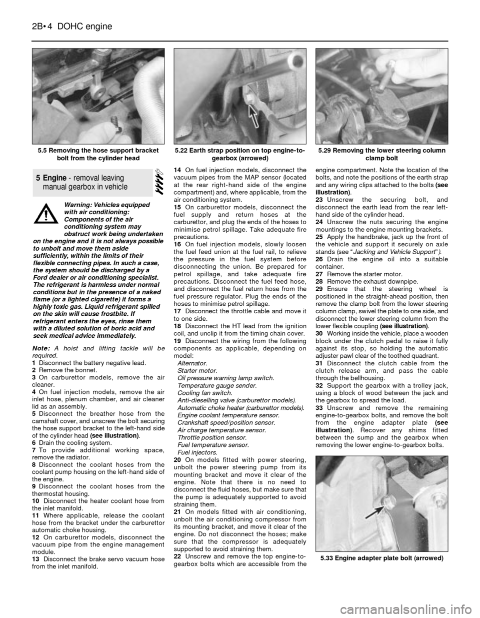
of the cylinder head (see illustration).
6Drain the cooling system.
7To provide additional working space,
remove the radiator.
8Disconnect the coolant hoses from the
coolant pump housing on the left-hand side of
the engine.
9Disconnect the coolant hoses from the
thermostat housing.
10Disconnect the heater coolant hose from
the inlet manifold.
11Where applicable, release the coolant
hose from the bracket under the carburettor
automatic choke housing.
12On carburettor models, disconnect the
vacuum pipe from the engine management
module.
13Disconnect the brake servo vacuum hose
from the inlet manifold.14On fuel injection models, disconnect the
vacuum pipes from the MAP sensor (located
at the rear right-hand side of the engine
compartment) and, where applicable, from the
air conditioning system.
15On carburettor models, disconnect the
fuel supply and return hoses at the
carburettor, and plug the ends of the hoses to
minimise petrol spillage. Take adequate fire
precautions.
16On fuel injection models, slowly loosen
the fuel feed union at the fuel rail, to relieve
the pressure in the fuel system before
disconnecting the union. Be prepared for
petrol spillage, and take adequate fire
precautions. Disconnect the fuel feed hose,
and disconnect the fuel return hose from the
fuel pressure regulator. Plug the ends of the
hoses to minimise petrol spillage.
17Disconnect the throttle cable and move it
to one side.
18Disconnect the HT lead from the ignition
coil, and unclip it from the timing chain cover.
19Disconnect the wiring from the following
components as applicable, depending on
model:
Alternator.
Starter motor.
Oil pressure warning lamp switch.
Temperature gauge sender.
Cooling fan switch.
Anti-dieselling valve (carburettor models).
Automatic choke heater (carburettor models).
Engine coolant temperature sensor.
Crankshaft speed/position sensor.
Air charge temperature sensor.
Throttle position sensor.
Fuel temperature sensor.
Fuel injectors.
20On models fitted with power steering,
unbolt the power steering pump from its
mounting bracket and move it clear of the
engine. Note that there is no need to
disconnect the fluid hoses, but make sure that
the pump is adequately supported to avoid
straining them.
21On models fitted with air conditioning,
unbolt the air conditioning compressor from
its mounting bracket, and move it clear of the
engine. Do not disconnect the hoses; make
sure that the compressor is adequately
supported to avoid straining them.
22Unscrew and remove the top engine-to-
gearbox bolts which are accessible from theengine compartment. Note the location of the
bolts, and note the positions of the earth strap
and any wiring clips attached to the bolts (see
illustration).
23Unscrew the securing bolt, and
disconnect the earth lead from the rear left-
hand side of the cylinder head.
24Unscrew the nuts securing the engine
mountings to the engine mounting brackets.
25Apply the handbrake, jack up the front of
the vehicle and support it securely on axle
stands (see “Jacking and Vehicle Support”).
26Drain the engine oil into a suitable
container.
27Remove the starter motor.
28Remove the exhaust downpipe.
29Ensure that the steering wheel is
positioned in the straight-ahead position, then
remove the clamp bolt from the lower steering
column clamp, swivel the plate to one side, and
disconnect the lower steering column from the
lower flexible coupling (see illustration).
30Working inside the vehicle, place a wooden
block under the clutch pedal to raise it fully
against its stop, so holding the automatic
adjuster pawl clear of the toothed quadrant.
31Disconnect the clutch cable from the
clutch release arm, and pass the cable
through the bellhousing.
32Support the gearbox with a trolley jack,
using a block of wood between the jack and
the gearbox to spread the load.
33Unscrew and remove the remaining
engine-to-gearbox bolts, and remove the bolt
from the engine adapter plate (see
illustration). Recover any shims fitted
between the sump and the gearbox when
removing the lower engine-to-gearbox bolts.
5Engine - removal leaving
manual gearbox in vehicle
2B•4DOHC engine
5.5 Removing the hose support bracket
bolt from the cylinder head5.29 Removing the lower steering column
clamp bolt
5.33 Engine adapter plate bolt (arrowed)
5.22 Earth strap position on top engine-to-
gearbox (arrowed)
Warning: Vehicles equipped
with air conditioning:
Components of the air
conditioning system may
obstruct work being undertaken
on the engine and it is not always possible
to unbolt and move them aside
sufficiently, within the limits of their
flexible connecting pipes. In such a case,
the system should be discharged by a
Ford dealer or air conditioning specialist.
The refrigerant is harmless under normal
conditions but in the presence of a naked
flame (or a lighted cigarette) it forms a
highly toxic gas. Liquid refrigerant spilled
on the skin will cause frostbite. If
refrigerant enters the eyes, rinse them
with a diluted solution of boric acid and
seek medical advice immediately.
Page 8 of 18
Dismantling
1Refer to Chapter 2, PartA, Section 18,
paragraphs 1 to 8 inclusive.
2A suitable selection of splined and Torx
sockets will be required to remove many of
the bolts when dismantling the engine.
3Before dismantling the main engine
components, the following externally-
mounted ancillary components can be
removed, with reference to the relevant
Chapters of this Manual and the relevant
Sections of this Chapter, where applicable.
Inlet manifold (and carburettor, if applicable)
Exhaust manifold
Alternator.
Coolant pump, and thermostat
Alternator/coolant pump drivebelt tensioner
Distributor cap, HT leads and spark plugs
Oil pressure warning lamp switch
Crankshaft speed/position sensor
Oil filter
Dipstick
Engine mounting brackets (if not already done)
Crankcase ventilation pipe and hoses
Clutch
Alternator mounting bracket.
Air conditioning compressor mounting
bracket (where applicable).
Engine lifting brackets.
Examination and renovation
4Refer to Chapter 2, PartA, Section 18, but
note that the connecting rod bolts should be
renewed on reassembly, and when renewing
the cylinder head bolts, the latest type bolts
with hexagonal heads should always be used.
Reassembly
5Proceed as described in Chapter 2, PartA,
Section 18, noting the following:
6If they have been removed, new cylinder
head bolts (both M11 and M8, of the latest
type with hexagonal heads), flywheel bolts,
and connecting rod bolts must be used.
Note: Refer to the warning at the beginning of
Section 5 before proceeding. A suitable puller
will be required to remove the crankshaft pulley.
A new crankshaft pulley bolt, a new timing chain
tensioner plunger assembly, new upper and
lower timing chain cover gaskets, and a new
camshaft cover gasket and reinforcing sleeve
sealing rings, must be used on refitting.
Removal
1If the engine is in the car, carry out the
following operations:
a)Disconnect the battery negative lead.
b)To improve access, remove the radiator. It
will be difficult to remove the crankshaft
pulley with the radiator in place.c)On carburettor models, remove the air
cleaner.
d)On fuel injection models, remove the air
inlet hose, plenum chamber, and air
cleaner lid as an assembly.
e)Disconnect the breather hose from the
camshaft cover.
f)Remove the distributor cap and HT leads,
and the rotor arm and housing.
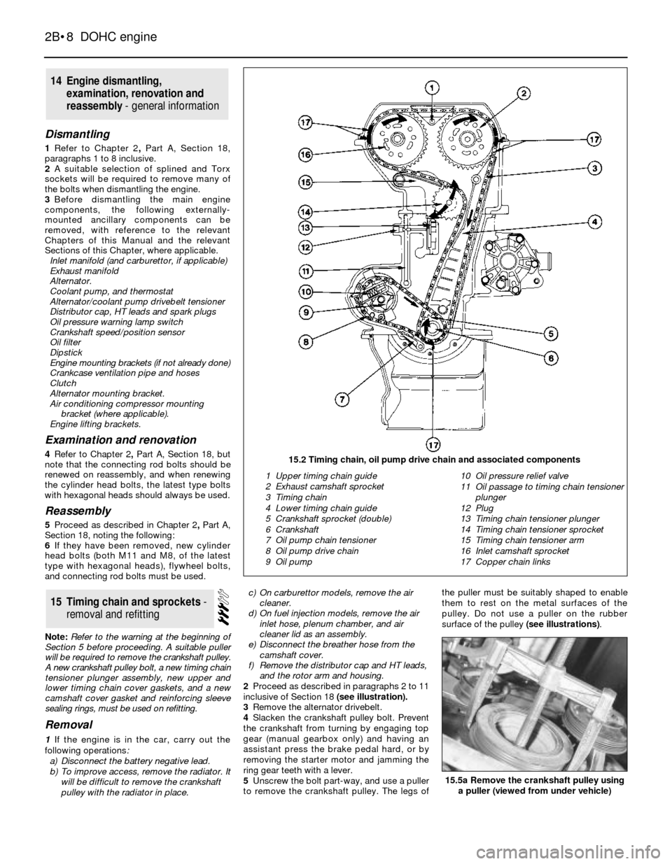
2Proceed as described in paragraphs 2 to 11
inclusive of Section 18 (see illustration).
3Remove the alternator drivebelt.
4Slacken the crankshaft pulley bolt. Prevent
the crankshaft from turning by engaging top
gear (manual gearbox only) and having an
assistant press the brake pedal hard, or by
removing the starter motor and jamming the
ring gear teeth with a lever.
5Unscrew the bolt part-way, and use a puller
to remove the crankshaft pulley. The legs ofthe puller must be suitably shaped to enable
them to rest on the metal surfaces of the
pulley. Do not use a puller on the rubber
surface of the pulley (see illustrations).
15Timing chain and sprockets -
removal and refitting
14Engine dismantling,
examination, renovation and
reassembly - general information
2B•8DOHC engine
15.2 Timing chain, oil pump drive chain and associated components
1 Upper timing chain guide
2 Exhaust camshaft sprocket
3 Timing chain
4 Lower timing chain guide
5 Crankshaft sprocket (double)
6 Crankshaft
7 Oil pump chain tensioner
8 Oil pump drive chain
9 Oil pump10 Oil pressure relief valve
11 Oil passage to timing chain tensioner
plunger
12 Plug
13 Timing chain tensioner plunger
14 Timing chain tensioner sprocket
15 Timing chain tensioner arm
16 Inlet camshaft sprocket
17 Copper chain links
15.5a Remove the crankshaft pulley using
a puller (viewed from under vehicle)
Page 12 of 18
11Lift the chain tensioner plunger assembly
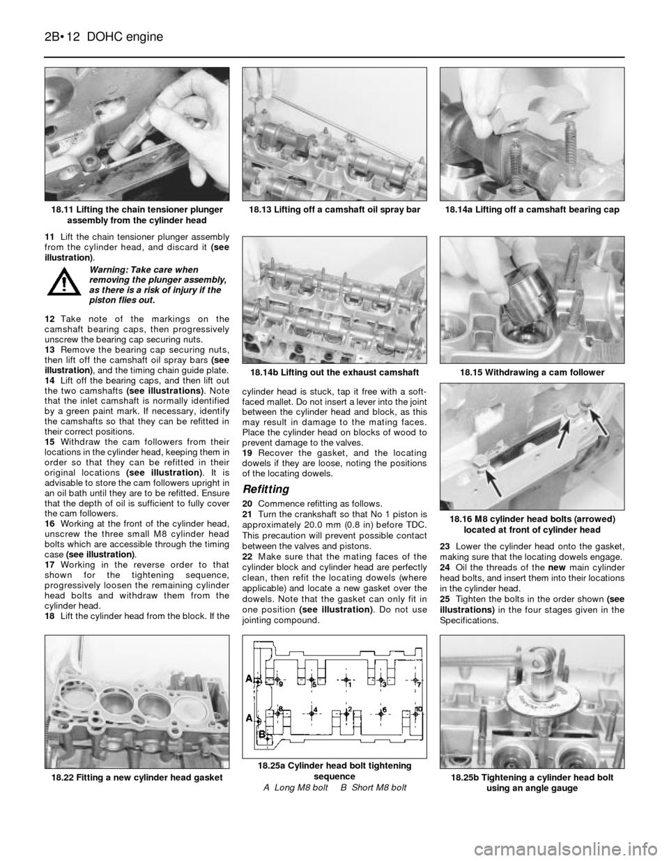
from the cylinder head, and discard it (see
illustration).
12Take note of the markings on the
camshaft bearing caps, then progressively
unscrew the bearing cap securing nuts.
13Remove the bearing cap securing nuts,
then lift off the camshaft oil spray bars (see
illustration), and the timing chain guide plate.
14Lift off the bearing caps, and then lift out
the two camshafts (see illustrations). Note
that the inlet camshaft is normally identified
by a green paint mark. If necessary, identify
the camshafts so that they can be refitted in
their correct positions.
15Withdraw the cam followers from their
locations in the cylinder head, keeping them in
order so that they can be refitted in their
original locations (see illustration). It is
advisable to store the cam followers upright in
an oil bath until they are to be refitted. Ensure
that the depth of oil is sufficient to fully cover
the cam followers.
16Working at the front of the cylinder head,
unscrew the three small M8 cylinder head
bolts which are accessible through the timing
case (see illustration).
17Working in the reverse order to that
shown for the tightening sequence,
progressively loosen the remaining cylinder
head bolts and withdraw them from the
cylinder head.
18Lift the cylinder head from the block. If thecylinder head is stuck, tap it free with a soft-
faced mallet. Do not insert a lever into the joint
between the cylinder head and block, as this
may result in damage to the mating faces.
Place the cylinder head on blocks of wood to
prevent damage to the valves.
19Recover the gasket, and the locating
dowels if they are loose, noting the positions
of the locating dowels.
Refitting
20Commence refitting as follows.
21Turn the crankshaft so that No 1 piston is
approximately 20.0 mm (0.8 in) before TDC.
This precaution will prevent possible contact
between the valves and pistons.
22Make sure that the mating faces of the
cylinder block and cylinder head are perfectly
clean, then refit the locating dowels (where
applicable) and locate a new gasket over the
dowels. Note that the gasket can only fit in
one position (see illustration). Do not use
jointing compound.23Lower the cylinder head onto the gasket,
making sure that the locating dowels engage.
24Oil the threads of the new main cylinder
head bolts, and insert them into their locations
in the cylinder head.
25Tighten the bolts in the order shown (see
illustrations)in the four stages given in the
Specifications.
2B•12DOHC engine
18.11 Lifting the chain tensioner plunger
assembly from the cylinder head18.14a Lifting off a camshaft bearing cap
18.25b Tightening a cylinder head bolt
using an angle gauge
18.25a Cylinder head bolt tightening
sequence
A Long M8 bolt B Short M8 bolt18.22 Fitting a new cylinder head gasket
18.16 M8 cylinder head bolts (arrowed)
located at front of cylinder head
18.15 Withdrawing a cam follower18.14b Lifting out the exhaust camshaft
18.13 Lifting off a camshaft oil spray bar
Warning: Take care when
removing the plunger assembly,
as there is a risk of injury if the
piston flies out.
Page 14 of 18
42Fit a new upper timing chain guide to the
plate at the front of the cylinder head.
43Turn the crankshaft clockwise until the
inlet camshaft begins to turn.
44If the chain tensioner plunger piston
protrudes from the cylinder, unlatch the piston
by pressing the chain tensioner arm down by
hand.
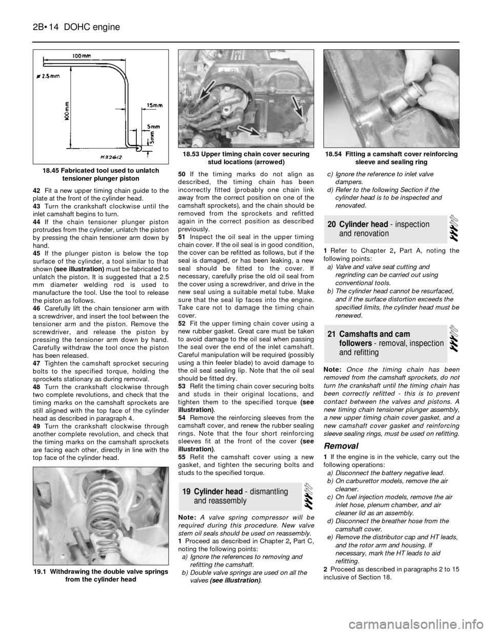
45If the plunger piston is below the top
surface of the cylinder, a tool similar to that
shown(see illustration)must be fabricated to
unlatch the piston. It is suggested that a 2.5
mm diameter welding rod is used to
manufacture the tool. Use the tool to release
the piston as follows.
46Carefully lift the chain tensioner arm with
a screwdriver, and insert the tool between the
tensioner arm and the piston. Remove the
screwdriver, and release the piston by
pressing the tensioner arm down by hand.
Carefully withdraw the tool once the piston
has been released.
47Tighten the camshaft sprocket securing
bolts to the specified torque, holding the
sprockets stationary as during removal.
48Turn the crankshaft clockwise through
two complete revolutions, and check that the
timing marks on the camshaft sprockets are
still aligned with the top face of the cylinder
head as described in paragraph 4.
49Turn the crankshaft clockwise through
another complete revolution, and check that
the timing marks on the camshaft sprockets
are facing each other, directly in line with the
top face of the cylinder head. 50If the timing marks do not align as
described, the timing chain has been
incorrectly fitted (probably one chain link
away from the correct position on one of the
camshaft sprockets), and the chain should be
removed from the sprockets and refitted
again in the correct position as described
previously.
51Inspect the oil seal in the upper timing
chain cover. If the oil seal is in good condition,
the cover can be refitted as follows, but if the
seal is damaged, or has been leaking, a new
seal should be fitted to the cover. If
necessary, carefully prise the old oil seal from
the cover using a screwdriver, and drive in the
new seal using a suitable metal tube. Make
sure that the seal lip faces into the engine.
Take care not to damage the timing chain
cover.
52Fit the upper timing chain cover using a
new rubber gasket. Great care must be taken
to avoid damage to the oil seal when passing
the seal over the end of the inlet camshaft.
Careful manipulation will be required (possibly
using a thin feeler blade) to avoid damage to
the oil seal sealing lip. Note that the oil seal
should be fitted dry.
53Refit the timing chain cover securing bolts
and studs in their original locations, and
tighten them to the specified torque (see
illustration).
54Remove the reinforcing sleeves from the
camshaft cover, and renew the rubber sealing
rings. Note that the four short reinforcing
sleeves fit at the front of the cover (see
illustration).
55Refit the camshaft cover using a new
gasket, and tighten the securing bolts and
studs to the specified torque.
Note: A valve spring compressor will be
required during this procedure. New valve
stem oil seals should be used on reassembly.
1Proceed as described in Chapter 2, PartC,
noting the following points:
a)Ignore the references to removing and
refitting the camshaft.
b)Double valve springs are used on all the
valves (see illustration).c)Ignore the reference to inlet valve
dampers.
d)Refer to the following Section if the
cylinder head is to be inspected and
renovated.
1Refer to Chapter 2, PartA, noting the
following points:
a)Valve and valve seat cutting and
regrinding can be carried out using
conventional tools.
b)The cylinder head cannot be resurfaced,
and if the surface distortion exceeds the
specified limits, the cylinder head must be
renewed.
Note: Once the timing chain has been
removed from the camshaft sprockets, do not
turn the crankshaft until the timing chain has
been correctly refitted - this is to prevent
contact between the valves and pistons. A
new timing chain tensioner plunger assembly,
a new upper timing chain cover gasket, and a
new camshaft cover gasket and reinforcing
sleeve sealing rings, must be used on refitting.
Removal
1If the engine is in the vehicle, carry out the
following operations:
a)Disconnect the battery negative lead.
b)On carburettor models, remove the air
cleaner.
c)On fuel injection models, remove the air
inlet hose, plenum chamber, and air
cleaner lid as an assembly.
d)Disconnect the breather hose from the
camshaft cover.
e)Remove the distributor cap and HT leads,
and the rotor arm and housing. If
necessary, mark the HT leads to aid
refitting.
2Proceed as described in paragraphs 2 to 15
inclusive of Section 18.
21Camshafts and cam
followers - removal, inspection
and refitting
20Cylinder head - inspection
and renovation
19Cylinder head - dismantling
and reassembly
2B•14DOHC engine
18.45 Fabricated tool used to unlatch
tensioner plunger piston
18.54 Fitting a camshaft cover reinforcing
sleeve and sealing ring
19.1 Withdrawing the double valve springs
from the cylinder head
18.53 Upper timing chain cover securing
stud locations (arrowed)
Page 17 of 18
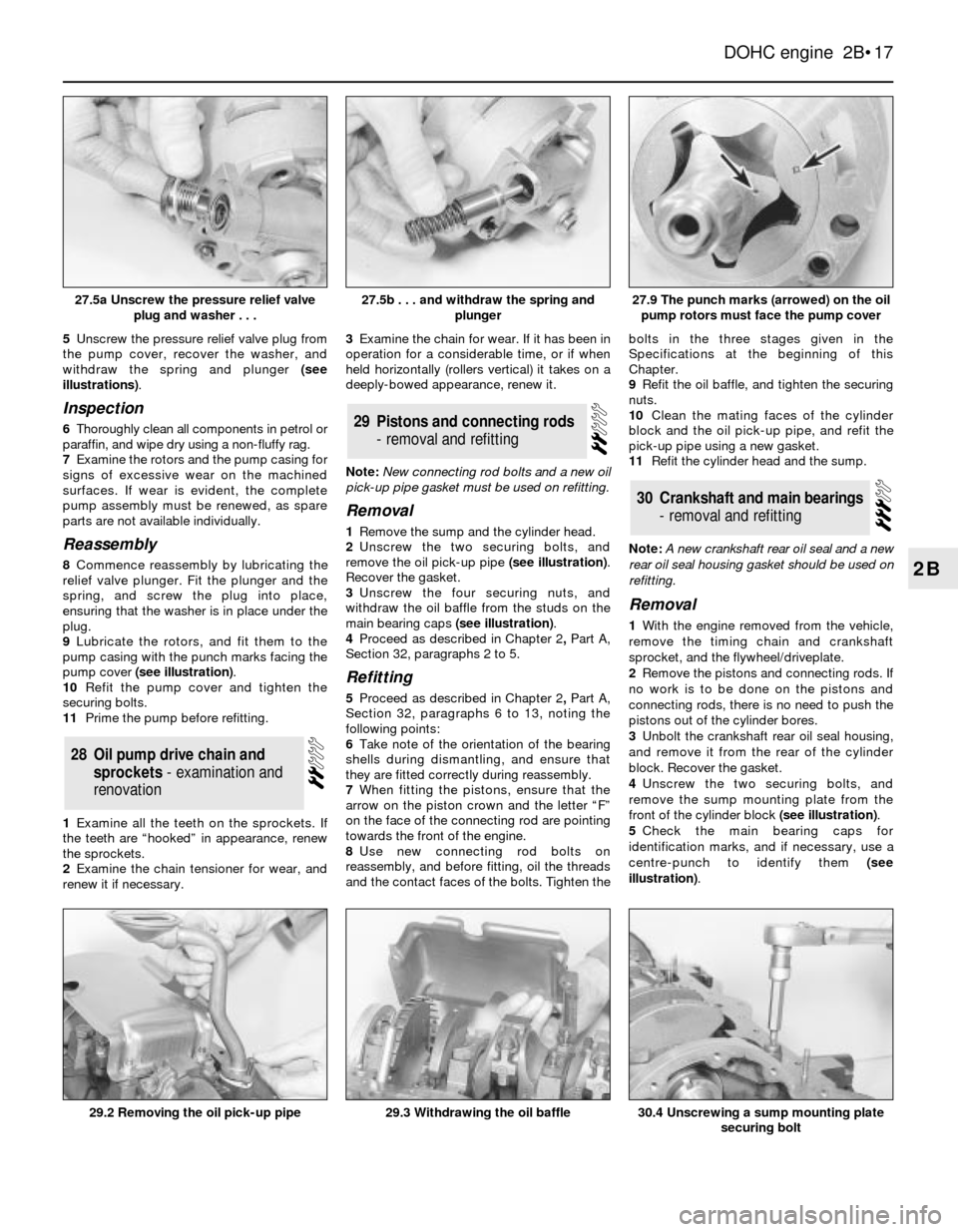
5Unscrew the pressure relief valve plug from
the pump cover, recover the washer, and
withdraw the spring and plunger (see
illustrations).
Inspection
6Thoroughly clean all components in petrol or
paraffin, and wipe dry using a non-fluffy rag.
7Examine the rotors and the pump casing for
signs of excessive wear on the machined
surfaces. If wear is evident, the complete
pump assembly must be renewed, as spare
parts are not available individually.
Reassembly
8Commence reassembly by lubricating the
relief valve plunger. Fit the plunger and the
spring, and screw the plug into place,
ensuring that the washer is in place under the
plug.
9Lubricate the rotors, and fit them to the
pump casing with the punch marks facing the
pump cover (see illustration).
10Refit the pump cover and tighten the
securing bolts.
11Prime the pump before refitting.
1Examine all the teeth on the sprockets. If
the teeth are “hooked” in appearance, renew
the sprockets.
2Examine the chain tensioner for wear, and
renew it if necessary.3Examine the chain for wear. If it has been in
operation for a considerable time, or if when
held horizontally (rollers vertical) it takes on a
deeply-bowed appearance, renew it.
Note: New connecting rod bolts and a new oil
pick-up pipe gasket must be used on refitting.
Removal
1Remove the sump and the cylinder head.
2Unscrew the two securing bolts, and
remove the oil pick-up pipe (see illustration).
Recover the gasket.
3Unscrew the four securing nuts, and
withdraw the oil baffle from the studs on the
main bearing caps (see illustration).
4Proceed as described in Chapter 2, PartA,
Section 32, paragraphs 2 to 5.
Refitting
5Proceed as described in Chapter 2, PartA,
Section 32, paragraphs 6 to 13, noting the
following points:
6Take note of the orientation of the bearing
shells during dismantling, and ensure that
they are fitted correctly during reassembly.
7When fitting the pistons, ensure that the
arrow on the piston crown and the letter “F”
on the face of the connecting rod are pointing
towards the front of the engine.
8Use new connecting rod bolts on
reassembly, and before fitting, oil the threads
and the contact faces of the bolts. Tighten thebolts in the three stages given in the
Specifications at the beginning of this
Chapter.
9Refit the oil baffle, and tighten the securing
nuts.
10Clean the mating faces of the cylinder
block and the oil pick-up pipe, and refit the
pick-up pipe using a new gasket.
11Refit the cylinder head and the sump.
Note: A new crankshaft rear oil seal and a new
rear oil seal housing gasket should be used on
refitting.
Removal
1With the engine removed from the vehicle,
remove the timing chain and crankshaft
sprocket, and the flywheel/driveplate.
2Remove the pistons and connecting rods. If
no work is to be done on the pistons and
connecting rods, there is no need to push the
pistons out of the cylinder bores.
3Unbolt the crankshaft rear oil seal housing,
and remove it from the rear of the cylinder
block. Recover the gasket.
4Unscrew the two securing bolts, and
remove the sump mounting plate from the
front of the cylinder block (see illustration).
5Check the main bearing caps for
identification marks, and if necessary, use a
centre-punch to identify them (see
illustration).
30Crankshaft and main bearings
- removal and refitting
29Pistons and connecting rods
- removal and refitting
28Oil pump drive chain and
sprockets - examination and
renovation
DOHC engine 2B•17
2B
27.5b . . . and withdraw the spring and
plunger
30.4 Unscrewing a sump mounting plate
securing bolt29.3 Withdrawing the oil baffle29.2 Removing the oil pick-up pipe
27.9 The punch marks (arrowed) on the oil
pump rotors must face the pump cover27.5a Unscrew the pressure relief valve
plug and washer . . .