radiator FORD SIERRA 1992 2.G DOHC Engine Workshop Manual
[x] Cancel search | Manufacturer: FORD, Model Year: 1992, Model line: SIERRA, Model: FORD SIERRA 1992 2.GPages: 18, PDF Size: 0.9 MB
Page 4 of 18

Note:A hoist and lifting tackle will be
required.
1Disconnect the battery negative lead.
2Remove the bonnet.
3On carburettor models, remove the air
cleaner.
4On fuel injection models, remove the air
inlet hose, plenum chamber, and air cleaner
lid as an assembly.
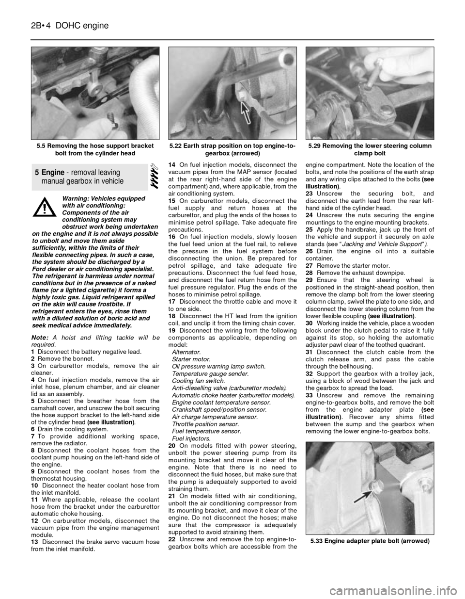
5Disconnect the breather hose from the
camshaft cover, and unscrew the bolt securing
the hose support bracket to the left-hand side
of the cylinder head (see illustration).
6Drain the cooling system.
7To provide additional working space,
remove the radiator.
8Disconnect the coolant hoses from the
coolant pump housing on the left-hand side of
the engine.
9Disconnect the coolant hoses from the
thermostat housing.
10Disconnect the heater coolant hose from
the inlet manifold.
11Where applicable, release the coolant
hose from the bracket under the carburettor
automatic choke housing.
12On carburettor models, disconnect the
vacuum pipe from the engine management
module.
13Disconnect the brake servo vacuum hose
from the inlet manifold.14On fuel injection models, disconnect the
vacuum pipes from the MAP sensor (located
at the rear right-hand side of the engine
compartment) and, where applicable, from the
air conditioning system.
15On carburettor models, disconnect the
fuel supply and return hoses at the
carburettor, and plug the ends of the hoses to
minimise petrol spillage. Take adequate fire
precautions.
16On fuel injection models, slowly loosen
the fuel feed union at the fuel rail, to relieve
the pressure in the fuel system before
disconnecting the union. Be prepared for
petrol spillage, and take adequate fire
precautions. Disconnect the fuel feed hose,
and disconnect the fuel return hose from the
fuel pressure regulator. Plug the ends of the
hoses to minimise petrol spillage.
17Disconnect the throttle cable and move it
to one side.
18Disconnect the HT lead from the ignition
coil, and unclip it from the timing chain cover.
19Disconnect the wiring from the following
components as applicable, depending on
model:
Alternator.
Starter motor.
Oil pressure warning lamp switch.
Temperature gauge sender.
Cooling fan switch.
Anti-dieselling valve (carburettor models).
Automatic choke heater (carburettor models).
Engine coolant temperature sensor.
Crankshaft speed/position sensor.
Air charge temperature sensor.
Throttle position sensor.
Fuel temperature sensor.
Fuel injectors.
20On models fitted with power steering,
unbolt the power steering pump from its
mounting bracket and move it clear of the
engine. Note that there is no need to
disconnect the fluid hoses, but make sure that
the pump is adequately supported to avoid
straining them.
21On models fitted with air conditioning,
unbolt the air conditioning compressor from
its mounting bracket, and move it clear of the
engine. Do not disconnect the hoses; make
sure that the compressor is adequately
supported to avoid straining them.
22Unscrew and remove the top engine-to-
gearbox bolts which are accessible from theengine compartment. Note the location of the
bolts, and note the positions of the earth strap
and any wiring clips attached to the bolts (see
illustration).
23Unscrew the securing bolt, and
disconnect the earth lead from the rear left-
hand side of the cylinder head.
24Unscrew the nuts securing the engine
mountings to the engine mounting brackets.
25Apply the handbrake, jack up the front of
the vehicle and support it securely on axle
stands (see “Jacking and Vehicle Support”).
26Drain the engine oil into a suitable
container.
27Remove the starter motor.
28Remove the exhaust downpipe.
29Ensure that the steering wheel is
positioned in the straight-ahead position, then
remove the clamp bolt from the lower steering
column clamp, swivel the plate to one side, and
disconnect the lower steering column from the
lower flexible coupling (see illustration).
30Working inside the vehicle, place a wooden
block under the clutch pedal to raise it fully
against its stop, so holding the automatic
adjuster pawl clear of the toothed quadrant.
31Disconnect the clutch cable from the
clutch release arm, and pass the cable
through the bellhousing.
32Support the gearbox with a trolley jack,
using a block of wood between the jack and
the gearbox to spread the load.
33Unscrew and remove the remaining
engine-to-gearbox bolts, and remove the bolt
from the engine adapter plate (see
illustration). Recover any shims fitted
between the sump and the gearbox when
removing the lower engine-to-gearbox bolts.
5Engine - removal leaving
manual gearbox in vehicle
2B•4DOHC engine
5.5 Removing the hose support bracket
bolt from the cylinder head5.29 Removing the lower steering column
clamp bolt
5.33 Engine adapter plate bolt (arrowed)
5.22 Earth strap position on top engine-to-
gearbox (arrowed)
Warning: Vehicles equipped
with air conditioning:
Components of the air
conditioning system may
obstruct work being undertaken
on the engine and it is not always possible
to unbolt and move them aside
sufficiently, within the limits of their
flexible connecting pipes. In such a case,
the system should be discharged by a
Ford dealer or air conditioning specialist.
The refrigerant is harmless under normal
conditions but in the presence of a naked
flame (or a lighted cigarette) it forms a
highly toxic gas. Liquid refrigerant spilled
on the skin will cause frostbite. If
refrigerant enters the eyes, rinse them
with a diluted solution of boric acid and
seek medical advice immediately.
Page 8 of 18

Dismantling
1Refer to Chapter 2, PartA, Section 18,
paragraphs 1 to 8 inclusive.
2A suitable selection of splined and Torx
sockets will be required to remove many of
the bolts when dismantling the engine.
3Before dismantling the main engine
components, the following externally-
mounted ancillary components can be
removed, with reference to the relevant
Chapters of this Manual and the relevant
Sections of this Chapter, where applicable.
Inlet manifold (and carburettor, if applicable)
Exhaust manifold
Alternator.
Coolant pump, and thermostat
Alternator/coolant pump drivebelt tensioner
Distributor cap, HT leads and spark plugs
Oil pressure warning lamp switch
Crankshaft speed/position sensor
Oil filter
Dipstick
Engine mounting brackets (if not already done)
Crankcase ventilation pipe and hoses
Clutch
Alternator mounting bracket.
Air conditioning compressor mounting
bracket (where applicable).
Engine lifting brackets.
Examination and renovation
4Refer to Chapter 2, PartA, Section 18, but
note that the connecting rod bolts should be
renewed on reassembly, and when renewing
the cylinder head bolts, the latest type bolts
with hexagonal heads should always be used.
Reassembly
5Proceed as described in Chapter 2, PartA,
Section 18, noting the following:
6If they have been removed, new cylinder
head bolts (both M11 and M8, of the latest
type with hexagonal heads), flywheel bolts,
and connecting rod bolts must be used.
Note: Refer to the warning at the beginning of
Section 5 before proceeding. A suitable puller
will be required to remove the crankshaft pulley.
A new crankshaft pulley bolt, a new timing chain
tensioner plunger assembly, new upper and
lower timing chain cover gaskets, and a new
camshaft cover gasket and reinforcing sleeve
sealing rings, must be used on refitting.
Removal
1If the engine is in the car, carry out the
following operations:
a)Disconnect the battery negative lead.
b)To improve access, remove the radiator. It
will be difficult to remove the crankshaft
pulley with the radiator in place.c)On carburettor models, remove the air
cleaner.
d)On fuel injection models, remove the air
inlet hose, plenum chamber, and air
cleaner lid as an assembly.
e)Disconnect the breather hose from the
camshaft cover.
f)Remove the distributor cap and HT leads,
and the rotor arm and housing.
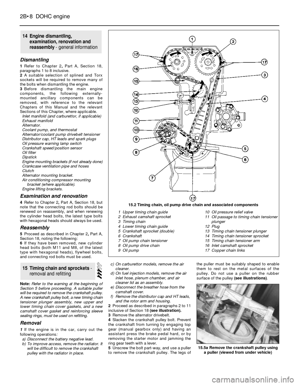
2Proceed as described in paragraphs 2 to 11
inclusive of Section 18 (see illustration).
3Remove the alternator drivebelt.
4Slacken the crankshaft pulley bolt. Prevent
the crankshaft from turning by engaging top
gear (manual gearbox only) and having an
assistant press the brake pedal hard, or by
removing the starter motor and jamming the
ring gear teeth with a lever.
5Unscrew the bolt part-way, and use a puller
to remove the crankshaft pulley. The legs ofthe puller must be suitably shaped to enable
them to rest on the metal surfaces of the
pulley. Do not use a puller on the rubber
surface of the pulley (see illustrations).
15Timing chain and sprockets -
removal and refitting
14Engine dismantling,
examination, renovation and
reassembly - general information
2B•8DOHC engine
15.2 Timing chain, oil pump drive chain and associated components
1 Upper timing chain guide
2 Exhaust camshaft sprocket
3 Timing chain
4 Lower timing chain guide
5 Crankshaft sprocket (double)
6 Crankshaft
7 Oil pump chain tensioner
8 Oil pump drive chain
9 Oil pump10 Oil pressure relief valve
11 Oil passage to timing chain tensioner
plunger
12 Plug
13 Timing chain tensioner plunger
14 Timing chain tensioner sprocket
15 Timing chain tensioner arm
16 Inlet camshaft sprocket
17 Copper chain links
15.5a Remove the crankshaft pulley using
a puller (viewed from under vehicle)
Page 15 of 18

Inspection
3Examine the surfaces of the camshaft
journals and lobes and the contact surfaces of
the cam followers for wear. If wear is
excessive considerable noise would have
been noticed from the top of the engine when
running, and new camshafts and followers
must be fitted. It is unlikely that this level of
wear will occur unless a considerable mileage
has been covered. Note that the cam
followers cannot be dismantled for renewal of
individual components.
4Check the camshaft bearing surfaces in the
cylinder head and the bearing caps for wear. If
excessive wear is evident, the only course of
action available is to renew the cylinder head
and bearing caps.
5Check the cam follower bores in the
cylinder head for wear. If excessive wear is
evident, the cylinder head must be renewed.
6Check the cam follower oil grooves and the
oil ports in the cylinder head for obstructions.
Refitting
7Refit the cam followers and the camshafts
as described in paragraphs 27 to 55 of
Section 18.
8If the engine is in the vehicle, reverse the
operations given in paragraph 1.
Note: New flywheel/driveplate securing bolts
must be used on refitting.
1Refer to Chapter 2, PartA, noting the
following points.
2If the engine is in the car, refer to Chapter 6
when removing and refitting the clutch.
3There is no need to make alignment marks
between the flywheel/driveplate and the end
of the crankshaft, as the securing bolt holes
are offset, so the flywheel/driveplate can only
be fitted to the crankshaft in one position.
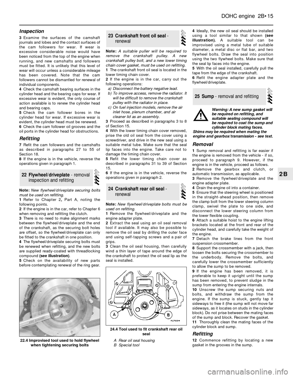
4The flywheel/driveplate securing bolts must
be renewed when refitting, and the new bolts
are supplied ready-coated with threadlocking
compound (see illustration).
5Check on the availability of new parts
before contemplating renewal of the ring gear.Note: A suitable puller will be required to
remove the crankshaft pulley. A new
crankshaft pulley bolt, and a new lower timing
chain cover gasket, must be used on refitting.
1The crankshaft front oil seal is located in the
lower timing chain cover.
2If the engine is in the car, carry out the
following operations:
a)Disconnect the battery negative lead.
b)To improve access, remove the radiator. It
will be difficult to remove the crankshaft
pulley with the radiator in place.
c)On fuel injection models, remove the air
inlet hose, plenum chamber, and air
cleaner lid as an assembly.
3Proceed as described in paragraphs 3 to 8
of Section 15.
4With the lower timing chain cover removed,
prise the old oil seal from the cover using a
screwdriver, and drive in the new seal using a
suitable metal tube. Make sure that the seal
lip faces into the engine. Take care not to
damage the timing chain cover.
5Refit the lower timing chain cover as
described in paragraphs 31 to 39 of Section
15.
6If the engine is in the vehicle, reverse the
operations given in paragraph 2.
Note: New flywheel/driveplate bolts must be
used on refitting.
1Remove the flywheel/driveplate and the
engine adapter plate.
2Extract the seal using an oil seal removal
tool if available. It may also be possible to
remove the oil seal by drilling the outer face
and using self-tapping screws and a pair of
grips.
3Clean the oil seal housing, then carefully
wind a thin layer of tape around the edge of
the crankshaft to protect the oil seal lip as the
seal is installed.4Ideally, the new oil seal should be installed
using a tool similar to that shown (see
illustration).A suitable tool can be
improvised using a metal tube of suitable
diameter, a metal disc or flat bar, and two
flywheel bolts. Draw the seal into position
using the two flywheel bolts. Make sure that
the seal lip faces into the engine.
5With the oil seal installed, carefully pull the
tape from the edge of the crankshaft.
6Refit the engine adapter plate and the
flywheel/driveplate.Removal
1Sump removal and refitting is far easier if
the engine is removed from the vehicle - if so,
proceed to paragraph 9. However, if the
engine is in the vehicle, proceed as follows.
2Remove the gearbox and clutch, or
automatic transmission, as applicable.
3Remove the flywheel/driveplate and the
engine adapter plate.
4Drain the engine oil into a container.
5Ensure that the steering wheel is positioned
in the straight-ahead position, then remove
the clamp bolt from the lower steering column
clamp, swivel the plate to one side, and
disconnect the lower steering column from
the lower flexible coupling.
6Attach a suitable hoist to the engine lifting
brackets located at the front and rear of the
cylinder head, and carefully take the weight of
the engine.
7Detach the brake lines from the front
suspension crossmember.
8Support the crossmember with a jack, then
loosen the bolts securing the crossmember to
the underbody. Remove the bolts, and
carefully lower the crossmember sufficiently
to allow the sump to be removed.
9If the engine has been removed, it is
preferable to keep it upright until the sump
has been removed, to prevent sludge in the
sump from entering the engine internals.
10Unscrew the sump securing nuts and
bolts, and withdraw the sump from the
engine. If the sump is stuck, gently tap it
sideways to free it (the sump will not move far
sideways, as it locates on studs in the cylinder
block). Do not prise between the mating faces
of the sump and block. Recover the gasket.
11Thoroughly clean the mating faces of the
cylinder block and sump.
Refitting
12Commence refitting by locating a new
gasket in the grooves in the sump.
25Sump - removal and refitting
24Crankshaft rear oil seal -
renewal
23Crankshaft front oil seal -
renewal
22Flywheel/driveplate - removal
inspection and refitting
DOHC engine 2B•15
2B
24.4 Tool used to fit crankshaft rear oil
seal
A Rear oil seal housing
B Special tool22.4 Improvised tool used to hold flywheel
when tightening securing bolts
Warning: A new sump gasket will
be required on refitting, and
suitable sealing compound will
be required to coat the sump and
cylinder block mating faces.
Shims may be required when mating the
engine and gearbox/transmission - see text.
Page 16 of 18

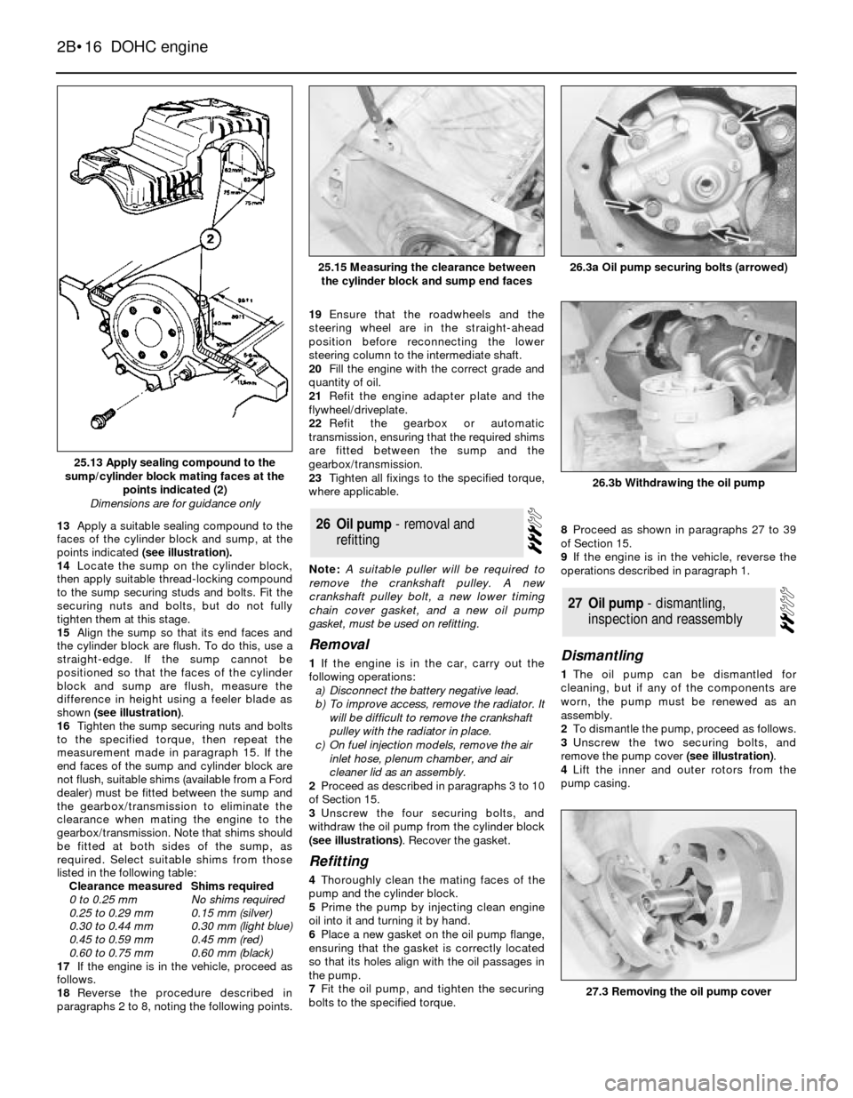
13Apply a suitable sealing compound to the
faces of the cylinder block and sump, at the
points indicated (see illustration).
14Locate the sump on the cylinder block,
then apply suitable thread-locking compound
to the sump securing studs and bolts. Fit the
securing nuts and bolts, but do not fully
tighten them at this stage.
15Align the sump so that its end faces and
the cylinder block are flush. To do this, use a
straight-edge. If the sump cannot be
positioned so that the faces of the cylinder
block and sump are flush, measure the
difference in height using a feeler blade as
shown (see illustration).
16Tighten the sump securing nuts and bolts
to the specified torque, then repeat the
measurement made in paragraph 15. If the
end faces of the sump and cylinder block are
not flush, suitable shims (available from a Ford
dealer) must be fitted between the sump and
the gearbox/transmission to eliminate the
clearance when mating the engine to the
gearbox/transmission. Note that shims should
be fitted at both sides of the sump, as
required. Select suitable shims from those
listed in the following table:
Clearance measuredShims required
0 to 0.25 mmNo shims required
0.25 to 0.29 mm0.15 mm (silver)
0.30 to 0.44 mm0.30 mm (light blue)
0.45 to 0.59 mm0.45 mm (red)
0.60 to 0.75 mm0.60 mm (black)
17If the engine is in the vehicle, proceed as
follows.
18Reverse the procedure described in
paragraphs 2 to 8, noting the following points.19Ensure that the roadwheels and the
steering wheel are in the straight-ahead
position before reconnecting the lower
steering column to the intermediate shaft.
20Fill the engine with the correct grade and
quantity of oil.
21Refit the engine adapter plate and the
flywheel/driveplate.
22Refit the gearbox or automatic
transmission, ensuring that the required shims
are fitted between the sump and the
gearbox/transmission.
23Tighten all fixings to the specified torque,
where applicable.
Note: A suitable puller will be required to
remove the crankshaft pulley. A new
crankshaft pulley bolt, a new lower timing
chain cover gasket, and a new oil pump
gasket, must be used on refitting.
Removal
1If the engine is in the car, carry out the
following operations:
a)Disconnect the battery negative lead.
b)To improve access, remove the radiator. It
will be difficult to remove the crankshaft
pulley with the radiator in place.
c)On fuel injection models, remove the air
inlet hose, plenum chamber, and air
cleaner lid as an assembly.
2Proceed as described in paragraphs 3 to 10
of Section 15.
3Unscrew the four securing bolts, and
withdraw the oil pump from the cylinder block
(see illustrations). Recover the gasket.
Refitting
4Thoroughly clean the mating faces of the
pump and the cylinder block.
5Prime the pump by injecting clean engine
oil into it and turning it by hand.
6Place a new gasket on the oil pump flange,
ensuring that the gasket is correctly located
so that its holes align with the oil passages in
the pump.
7Fit the oil pump, and tighten the securing
bolts to the specified torque.8Proceed as shown in paragraphs 27 to 39
of Section 15.
9If the engine is in the vehicle, reverse the
operations described in paragraph 1.
Dismantling
1The oil pump can be dismantled for
cleaning, but if any of the components are
worn, the pump must be renewed as an
assembly.
2To dismantle the pump, proceed as follows.
3Unscrew the two securing bolts, and
remove the pump cover (see illustration).
4Lift the inner and outer rotors from the
pump casing.
27Oil pump - dismantling,
inspection and reassembly
26Oil pump - removal and
refitting
2B•16DOHC engine
25.13 Apply sealing compound to the
sump/cylinder block mating faces at the
points indicated (2)
Dimensions are for guidance only
26.3b Withdrawing the oil pump
26.3a Oil pump securing bolts (arrowed)25.15 Measuring the clearance between
the cylinder block and sump end faces
27.3 Removing the oil pump cover