ECU FORD SIERRA 1992 2.G Engine Electrical Systems Workshop Manual
[x] Cancel search | Manufacturer: FORD, Model Year: 1992, Model line: SIERRA, Model: FORD SIERRA 1992 2.GPages: 24, PDF Size: 0.93 MB
Page 5 of 24
Never disconnect the battery terminals, or
alternator multi-plug connector, when the
engine is running.
The battery leads and alternator multi-plug
must be disconnected before carrying out any
electric welding on the car.
Never use an ohmmeter of the type
incorporating a hand cranked generator for
circuit or continuity testing.
Ignition and engine management
systems
Engine management modules are very
sensitive components, and certain
precautions must be taken to avoid damage
to the module when working on a vehicle
equipped with an engine management system
as follows.
When carrying out welding operations on
the vehicle using electric welding equipment,
the battery and alternator should be
disconnected.
Although underbonnet-mounted modules
(all except EEC IV) will tolerate normal
underbonnet conditions, they can be
adversely affected by excess heat or moisture.
If using welding equipment or pressure
washing equipment in the vicinity of the
module, take care not to direct heat, or jets of
water or steam at the module. If this cannot be
avoided, remove the module from the vehicle,
and protect its wiring plug with a plastic bag.
Before disconnecting any wiring, or
removing components, always ensure that the
ignition is switched off.
On models with underbonnet-mounted
modules, do not run the engine with the module
detached from the body panel, as the body acts
as an effective heat sink, and the module may
be damaged due to internal overheating.
Do not attempt to improvise fault diagnosis
procedures using a test lamp or multimeter,
as irreparable damage could be caused to the
module.
After working on ignition/engine
management system components, ensure
that all wiring is correctly reconnected before
reconnecting the battery or switching on the
ignition.
On some early Bosch distributors it is
possible that with the distributor cap removed,
if the engine is cranked, the cap securing clips
may fall inward and jam the trigger
wheel/vane, knocking it out of alignment. If this
happens, the distributor will have to be
renewed as the trigger wheel/vane cannot be
repositioned. Care should therefore be taken
not to crank the engine with the distributor cap
removed. Later distributors have redesigned
clips which eliminate the problem.
Removal
1The battery is located in the engine
compartment on the left-hand side of the
bulkhead.
2Disconnect the leads at the negative (earth)
terminal by unscrewing the retaining nut and
removing the bulb. Pull off the plastic cover,
and disconnect the positive terminal leads in
the same way.
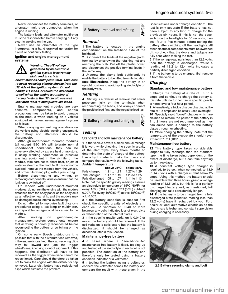
3Unscrew the clamp bolt sufficiently to
enable the battery to be lifted from its location
(see illustration). Keep the battery in an
upright position to avoid spilling electrolyte on
the bodywork.
Refitting
4Refitting is a reversal of removal, but smear
petroleum jelly on the terminals when
reconnecting the leads, and always connect
the positive lead first and the negative lead last.
Testing
Standard and low maintenance battery
1If the vehicle covers a small annual mileage
it is worthwhile checking the specific gravity
of the electrolyte every three months to
determine the state of charge of the battery.
Use a hydrometer to make the check and
compare the results with the following table.
Ambient temperature:
above 25ºCbelow 25ºC
Fully charged1.21 to 1.231.27 to 1.29
70% charged1.17 to 1.191.23 to 1.25
Fully discharged1.05 to 1.071.11 to 1.13
Note that the specific gravity readings assume
an electrolyte temperature of 15ºC (60ºF); for
every 10ºC (50ºF) below 15ºC (60ºF) subtract
0.007. For every 10ºC(50ºF) above 15ºC(60ºF)
add 0.007.
2If the battery condition is suspect first
check the specific gravity of electrolyte in
each cell. A variation of 0.040 or more
between any cells indicates loss of electrolyte
or deterioration of the internal plates.
3If the specific gravity variation is 0.040 or
more, the battery should be renewed. If the
cell variation is satisfactory but the battery is
discharged, it should be charged as
described later in this Section.
Maintenance-free battery
4In cases where a “sealed-for-life”
maintenance-free battery is fitted, topping-up
and testing of the electrolyte in each cell is not
possible. The condition of the battery can
therefore only be tested using a battery
condition indicator or a voltmeter.
5If testing the battery using a voltmeter,
connect the voltmeter across the battery and
compare the result with those given in theSpecifications under “charge condition”. The
test is only accurate if the battery has not
been subject to any kind of charge for the
previous six hours. If this is not the case,
switch on the headlights for 30 seconds, then
wait four to five minutes before testing the
battery after switching off the headlights. All
other electrical components must be switched
off, so check that the doors and tailgate are
fully shut when making the test.
6If the voltage reading is less than 12.2 volts,
then the battery is discharged, whilst a
reading of 12.2 to 12.4 volts indicates a
partially discharged condition.
7If the battery is to be charged, first remove
it from the vehicle.
Charging
Standard and low maintenance battery
8Charge the battery at a rate of 3.5 to 4
amps and continue to charge the battery at
this rate until no further rise in specific gravity
is noted over a four hour period.
9Alternatively, a trickle charger charging at the
rate of 1.5 amps can be safely used overnight.
10Specially rapid “boost” charges which are
claimed to restore the power of the battery in
1 to 2 hours are not recommended as they
can cause serious damage to the battery
plates through overheating.
11While charging the battery, note that the
temperature of the electrolyte should never
exceed 37.8ºC (100ºF).
Maintenance-free battery
12This battery type takes considerably
longer to fully recharge than the standard
type, the time taken being dependent on the
extent of discharge, but it can take anything
up to three days.
13A constant voltage type charger is
required, to be set, when connected, to 13.9
to 14.9 volts with a charger current below 25
amps. Using this method the battery should
be useable within three hours, giving a voltage
reading of 12.5 volts, but this is for a partially
discharged battery and, as mentioned, full
charging can take considerably longer.
14If the battery is to be charged from a fully
discharged state (condition reading less than
12.2 volts) have it recharged by your Ford
dealer or local automotive electrician as the
charge rate is higher and constant supervision
during charging is necessary.
3Battery - testing and charging
2Battery - removal and refitting
Engine electrical systems 5•5
5
2.3 Battery securing clamp and bolt
Warning: The HT voltage
generated by an electronic
ignition system is extremely
high, and in certain
circumstances could prove fatal. Take care
to avoid receiving electric shocks from the
HT side of the ignition system. Do not
handle HT leads, or touch the distributor
or coil when the engine is running. If
tracing faults in the HT circuit, use well
insulated tools to manipulate live leads.
Page 6 of 24
Removal
1Disconnect the battery leads.
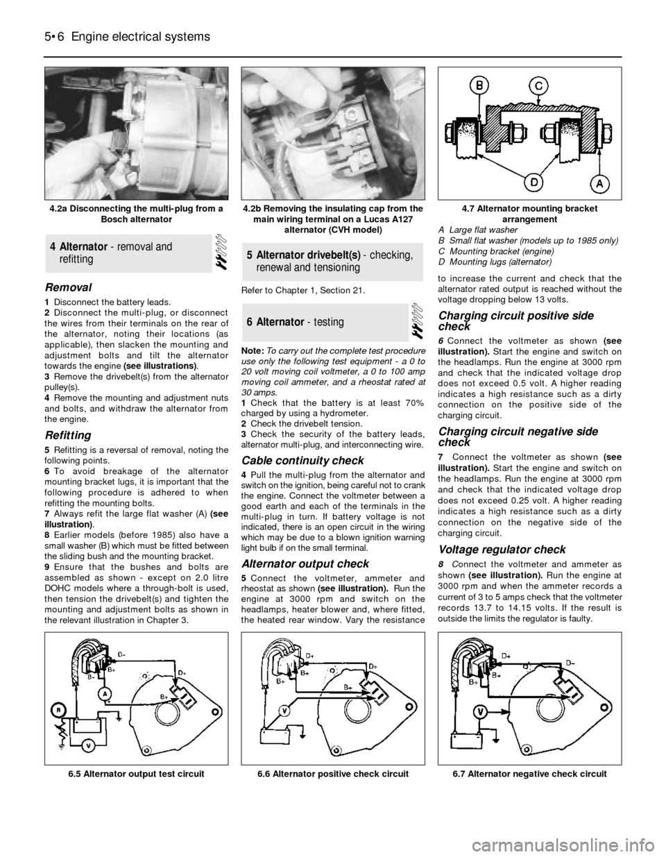
2Disconnect the multi-plug, or disconnect
the wires from their terminals on the rear of
the alternator, noting their locations (as
applicable), then slacken the mounting and
adjustment bolts and tilt the alternator
towards the engine (see illustrations).
3Remove the drivebelt(s) from the alternator
pulley(s).
4Remove the mounting and adjustment nuts
and bolts, and withdraw the alternator from
the engine.
Refitting
5Refitting is a reversal of removal, noting the
following points.
6To avoid breakage of the alternator
mounting bracket lugs, it is important that the
following procedure is adhered to when
refitting the mounting bolts.
7Always refit the large flat washer (A) (see
illustration).
8Earlier models (before 1985) also have a
small washer (B) which must be fitted between
the sliding bush and the mounting bracket.
9Ensure that the bushes and bolts are
assembled as shown - except on 2.0 litre
DOHC models where a through-bolt is used,
then tension the drivebelt(s) and tighten the
mounting and adjustment bolts as shown in
the relevant illustration in Chapter 3.Refer to Chapter 1, Section 21.
Note: To carry out the complete test procedure
use only the following test equipment - a 0 to
20 volt moving coil voltmeter, a 0 to 100 amp
moving coil ammeter, and a rheostat rated at
30 amps.
1Check that the battery is at least 70%
charged by using a hydrometer.
2Check the drivebelt tension.
3Check the security of the battery leads,
alternator multi-plug, and interconnecting wire.
Cable continuity check
4Pull the multi-plug from the alternator and
switch on the ignition, being careful not to crank
the engine. Connect the voltmeter between a
good earth and each of the terminals in the
multi-plug in turn. If battery voltage is not
indicated, there is an open circuit in the wiring
which may be due to a blown ignition warning
light bulb if on the small terminal.
Alternator output check
5Connect the voltmeter, ammeter and
rheostat as shown (see illustration).Run the
engine at 3000 rpm and switch on the
headlamps, heater blower and, where fitted,
the heated rear window. Vary the resistanceto increase the current and check that the
alternator rated output is reached without the
voltage dropping below 13 volts.
Charging circuit positive side
check
6Connect the voltmeter as shown (see
illustration).Start the engine and switch on
the headlamps. Run the engine at 3000 rpm
and check that the indicated voltage drop
does not exceed 0.5 volt. A higher reading
indicates a high resistance such as a dirty
connection on the positive side of the
charging circuit.
Charging circuit negative side
check
7Connect the voltmeter as shown (see
illustration).Start the engine and switch on
the headlamps. Run the engine at 3000 rpm
and check that the indicated voltage drop
does not exceed 0.25 volt. A higher reading
indicates a high resistance such as a dirty
connection on the negative side of the
charging circuit.
Voltage regulator check
8Connect the voltmeter and ammeter as
shown(see illustration).Run the engine at
3000 rpm and when the ammeter records a
current of 3 to 5 amps check that the voltmeter
records 13.7 to 14.15 volts. If the result is
outside the limits the regulator is faulty.
6Alternator - testing
5Alternator drivebelt(s) - checking,
renewal and tensioning4Alternator - removal and
refitting
5•6Engine electrical systems
4.2a Disconnecting the multi-plug from a
Bosch alternator4.7 Alternator mounting bracket
arrangement
A Large flat washer
B Small flat washer (models up to 1985 only)
C Mounting bracket (engine)
D Mounting lugs (alternator)
6.7 Alternator negative check circuit6.6 Alternator positive check circuit6.5 Alternator output test circuit
4.2b Removing the insulating cap from the
main wiring terminal on a Lucas A127
alternator (CVH model)
Page 7 of 24
1Remove the alternator.
Bosch type
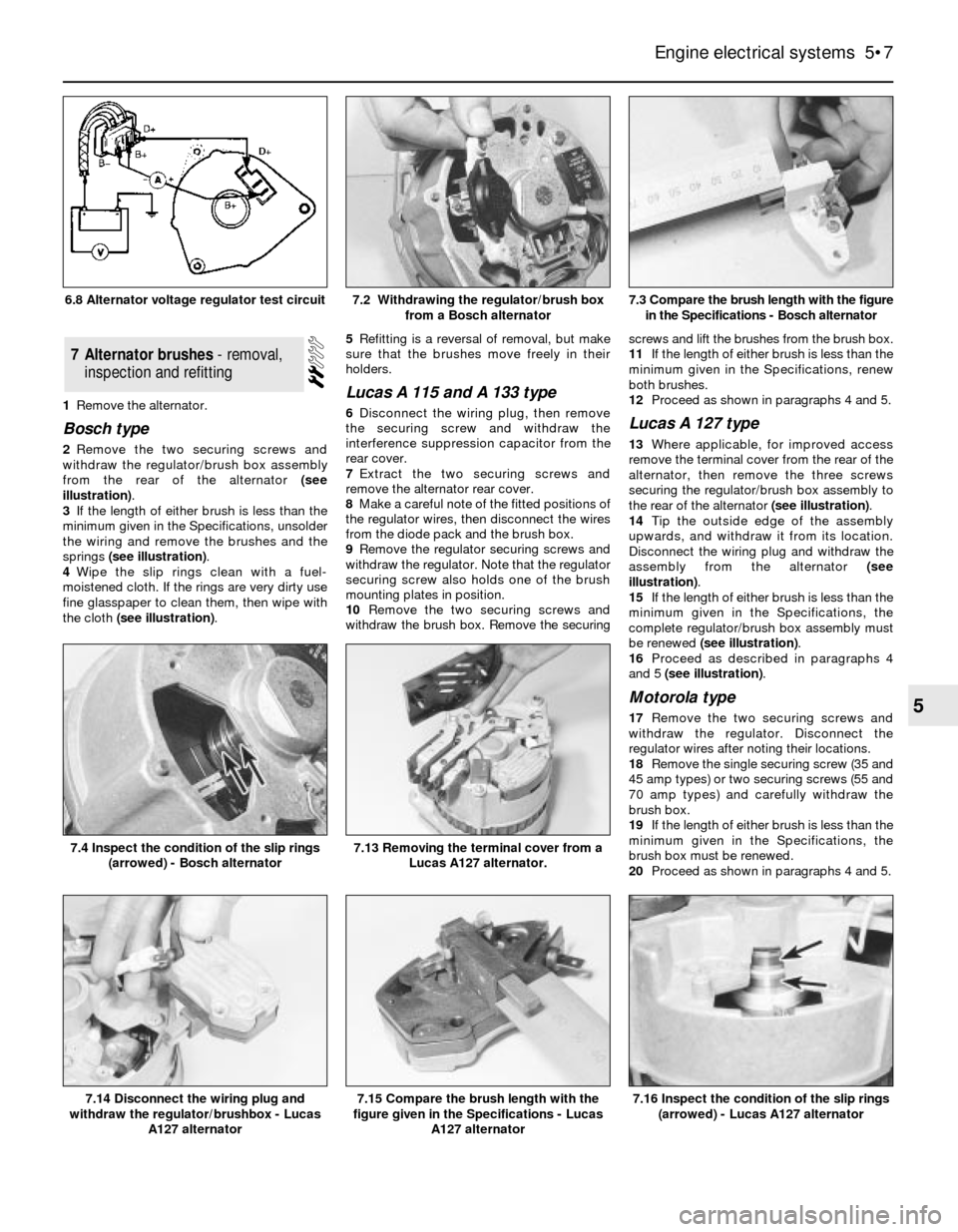
2Remove the two securing screws and
withdraw the regulator/brush box assembly
from the rear of the alternator (see
illustration).
3If the length of either brush is less than the
minimum given in the Specifications, unsolder
the wiring and remove the brushes and the
springs (see illustration).
4Wipe the slip rings clean with a fuel-
moistened cloth. If the rings are very dirty use
fine glasspaper to clean them, then wipe with
the cloth (see illustration).5Refitting is a reversal of removal, but make
sure that the brushes move freely in their
holders.
Lucas A 115 and A 133 type
6Disconnect the wiring plug, then remove
the securing screw and withdraw the
interference suppression capacitor from the
rear cover.
7Extract the two securing screws and
remove the alternator rear cover.
8Make a careful note of the fitted positions of
the regulator wires, then disconnect the wires
from the diode pack and the brush box.
9Remove the regulator securing screws and
withdraw the regulator. Note that the regulator
securing screw also holds one of the brush
mounting plates in position.
10Remove the two securing screws and
withdraw the brush box. Remove the securingscrews and lift the brushes from the brush box.
11If the length of either brush is less than the
minimum given in the Specifications, renew
both brushes.
12Proceed as shown in paragraphs 4 and 5.Lucas A 127 type
13Where applicable, for improved access
remove the terminal cover from the rear of the
alternator, then remove the three screws
securing the regulator/brush box assembly to
the rear of the alternator (see illustration).
14Tip the outside edge of the assembly
upwards, and withdraw it from its location.
Disconnect the wiring plug and withdraw the
assembly from the alternator (see
illustration).
15If the length of either brush is less than the
minimum given in the Specifications, the
complete regulator/brush box assembly must
be renewed (see illustration).
16Proceed as described in paragraphs 4
and 5 (see illustration).
Motorola type
17Remove the two securing screws and
withdraw the regulator. Disconnect the
regulator wires after noting their locations.
18Remove the single securing screw (35 and
45 amp types) or two securing screws (55 and
70 amp types) and carefully withdraw the
brush box.
19If the length of either brush is less than the
minimum given in the Specifications, the
brush box must be renewed.
20Proceed as shown in paragraphs 4 and 5.
7Alternator brushes - removal,
inspection and refitting
Engine electrical systems 5•7
5
7.3 Compare the brush length with the figure
in the Specifications - Bosch alternator
7.16 Inspect the condition of the slip rings
(arrowed) - Lucas A127 alternator7.15 Compare the brush length with the
figure given in the Specifications - Lucas
A127 alternator7.14 Disconnect the wiring plug and
withdraw the regulator/brushbox - Lucas
A127 alternator
7.13 Removing the terminal cover from a
Lucas A127 alternator.7.4 Inspect the condition of the slip rings
(arrowed) - Bosch alternator
7.2 Withdrawing the regulator/brush box
from a Bosch alternator6.8 Alternator voltage regulator test circuit
Page 8 of 24
Mitsubishi type
21Unscrew the pulley nut. To prevent the
shaft rotating, insert an Allen key in the end of
the shaft.
22Remove the spring washer, pulley, fan,
spacer and dust shield.
23Scribe an alignment mark along the length
of the alternator to facilitate reassembly of the
drive end housing, stator and rear housing.
24Unscrew the through-bolts and withdraw
the drive end housing from the rotor shaft.
25Remove the seal and spacer from the
rotor shaft.
26Remove the rotor from the rear housing
and the stator. This may require the
application of local heat to the rear housing
using a large soldering iron. Do not use a heat
gun, as this may result in damage to the
diodes.
27Unscrew the four securing bolts and
withdraw the diode pack stator assembly
from the rear housing.
28Unsolder the stator leads from the diode
pack terminals. Use a pair of pliers when
unsoldering to act as a heat sink, otherwise
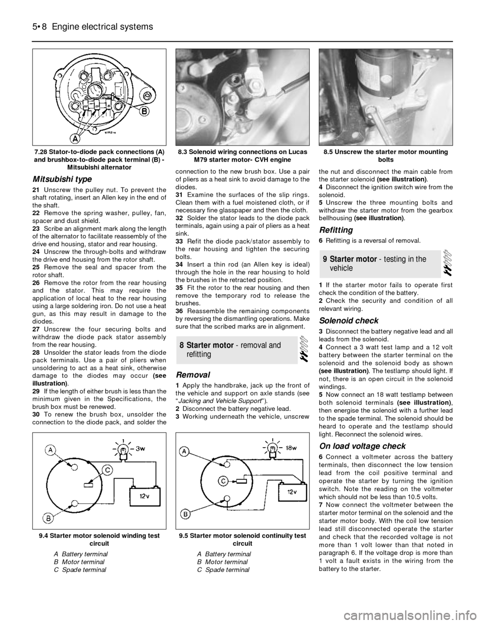
damage to the diodes may occur (see
illustration).
29If the length of either brush is less than the
minimum given in the Specifications, the
brush box must be renewed.
30To renew the brush box, unsolder the
connection to the diode pack, and solder theconnection to the new brush box. Use a pair
of pliers as a heat sink to avoid damage to the
diodes.
31Examine the surfaces of the slip rings.
Clean them with a fuel moistened cloth, or if
necessary fine glasspaper and then the cloth.
32Solder the stator leads to the diode pack
terminals, again using a pair of pliers as a heat
sink.
33Refit the diode pack/stator assembly to
the rear housing and tighten the securing
bolts.
34Insert a thin rod (an Allen key is ideal)
through the hole in the rear housing to hold
the brushes in the retracted position.
35Fit the rotor to the rear housing and then
remove the temporary rod to release the
brushes.
36Reassemble the remaining components
by reversing the dismantling operations. Make
sure that the scribed marks are in alignment.
Removal
1Apply the handbrake, jack up the front of
the vehicle and support on axle stands (see
“Jacking and Vehicle Support”).
2Disconnect the battery negative lead.
3Working underneath the vehicle, unscrewthe nut and disconnect the main cable from
the starter solenoid (see illustration).
4Disconnect the ignition switch wire from the
solenoid.
5Unscrew the three mounting bolts and
withdraw the starter motor from the gearbox
bellhousing (see illustration).
Refitting
6Refitting is a reversal of removal.
1If the starter motor fails to operate first
check the condition of the battery.
2Check the security and condition of all
relevant wiring.
Solenoid check
3Disconnect the battery negative lead and all
leads from the solenoid.
4Connect a 3 watt test lamp and a 12 volt
battery between the starter terminal on the
solenoid and the solenoid body as shown
(see illustration). The testlamp should light. If
not, there is an open circuit in the solenoid
windings.
5Now connect an 18 watt testlamp between
both solenoid terminals (see illustration),
then energise the solenoid with a further lead
to the spade terminal. The solenoid should be
heard to operate and the testlamp should
light. Reconnect the solenoid wires.
On load voltage check
6Connect a voltmeter across the battery
terminals, then disconnect the low tension
lead from the coil positive terminal and
operate the starter by turning the ignition
switch. Note the reading on the voltmeter
which should not be less than 10.5 volts.
7Now connect the voltmeter between the
starter motor terminal on the solenoid and the
starter motor body. With the coil low tension
lead still disconnected operate the starter
and check that the recorded voltage is not
more than 1 volt lower than that noted in
paragraph 6. If the voltage drop is more than
1 volt a fault exists in the wiring from the
battery to the starter.
9Starter motor - testing in the
vehicle
8Starter motor - removal and
refitting
5•8Engine electrical systems
7.28 Stator-to-diode pack connections (A)
and brushbox-to-diode pack terminal (B) -
Mitsubishi alternator8.5 Unscrew the starter motor mounting
bolts
9.5 Starter motor solenoid continuity test
circuit
A Battery terminal
B Motor terminal
C Spade terminal
9.4 Starter motor solenoid winding test
circuit
A Battery terminal
B Motor terminal
C Spade terminal
8.3 Solenoid wiring connections on Lucas
M79 starter motor- CVH engine
Page 9 of 24
8Connect the voltmeter between the battery
positive terminal and the terminal on the
starter motor. With the coil low tension lead
disconnected operate the starter for two or
three seconds. Battery voltage should be
indicated initially, then dropping to less than 1
volt. If the reading is more than 1 volt, there is
a high resistance in the wiring from the battery
to the starter and the check in paragraph 9
should be made. If the reading is less than 1
volt proceed to paragraph 10.
9Connect the voltmeter between the two
main solenoid terminals and operate the
starter for two or three seconds. Battery
voltage should be indicated initially, then
dropping to less than 0.5 volt. If the reading is
more than 0.5 volt, the ignition switch and
connections may be faulty.
10Connect the voltmeter between the
battery negative terminal and the starter
motor body, and operate the starter for two or
three seconds. A reading of less than 0.5 volt
should be recorded. If the reading is more
than 0.5 volt, there is a fault in the earth
circuit, and the earth connections to the
battery and body should be checked.
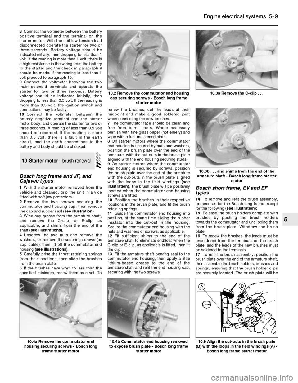
Bosch long frame and JF, and
Cajavec types
1With the starter motor removed from the
vehicle and cleaned, grip the unit in a vice
fitted with soft jaw protectors.
2Remove the two screws securing the
commutator end housing cap, then remove
the cap and rubber seal (see illustration).
3Wipe any grease from the armature shaft,
and remove the C-clip, or E-clip, as
applicable, and shims from the end of the
shaft (see illustrations).
4Unscrew the two nuts and remove the
washers, or remove the securing screws (as
applicable), then lift off the commutator end
housing (see illustrations).
5Carefully prise the thrust retaining springs
from their locations, then slide the brushes
from the brush plate.
6If the brushes have worn to less than the
specified minimum, renew them as a set. Torenew the brushes, cut the leads at their
midpoint and make a good soldered joint
when connecting the new brushes.
7The commutator face should be clean and
free from burnt spots. Where necessary
burnish with fine glass paper (not emery) and
wipe with a fuel-moistened cloth.
8On starter motors where the commutator
end housing is secured by nuts and washers,
position the brush plate over the end of the
armature, with the cut-outs in the brush plate
aligned with the end housing securing studs.
9On starter motors where the commutator
end housing is secured by screws, position
the brush plate over the end of the armature
with the cut-outs in the brush plate aligned
with the loops in the field windings (see
illustration). The brush plate will be positively
located when the commutator end housing
screws are fitted.
10Position the brushes in their respective
locations in the brush plate, and fit the brush
retaining springs.
11Guide the commutator end housing into
position, at the same time sliding the rubber
insulator into the cut-out in the housing.
Secure the commutator end housing with the
nuts and washers or screws, as applicable.
12Fit sufficient shims to the end of the
armature shaft to eliminate endfloat when the
C-clip or E-clip, as applicable is fitted, then fit
the clip.
13Fit the armature shaft bearing seal to the
commutator end housing, then apply a little
lithium-based grease to the end of the
armature shaft and refit the end housing cap,
securing with the two screws.Bosch short frame, EV and EF
types
14To remove and refit the brush assembly,
proceed as for the Bosch long frame except
for the following(see illustration):
15Release the brush holders complete with
brushes by pushing the brush holders
towards the commutator and unclipping them
from the brush plate. Withdraw the brush
plate.
16To renew the brushes, the leads must be
unsoldered from the terminals on the brush
plate, and the leads of the new brushes must
be soldered to the terminals.
17To refit the brush assembly, position the
brush plate over the end of the armature shaft,
then assemble the brush holders, brushes and
springs, ensuring that the brush holder clips
are securely located. The brush plate will be
10Starter motor - brush renewal
Engine electrical systems 5•9
5
10.3b . . . and shims from the end of the
armature shaft - Bosch long frame starter
motor
10.9 Align the cut-outs in the brush plate
(B) with the loops in the field windings (A) -
Bosch long frame starter motor10.4b Commutator end housing removed
to expose brush plate - Bosch long frame
starter motor10.4a Remove the commutator end
housing securing screws - Bosch long
frame starter motor
10.3a Remove the C-clip . . .10.2 Remove the commutator end housing
cap securing screws - Bosch long frame
starter motor
Page 10 of 24
positively located when the commutator end
housing screws are fitted.
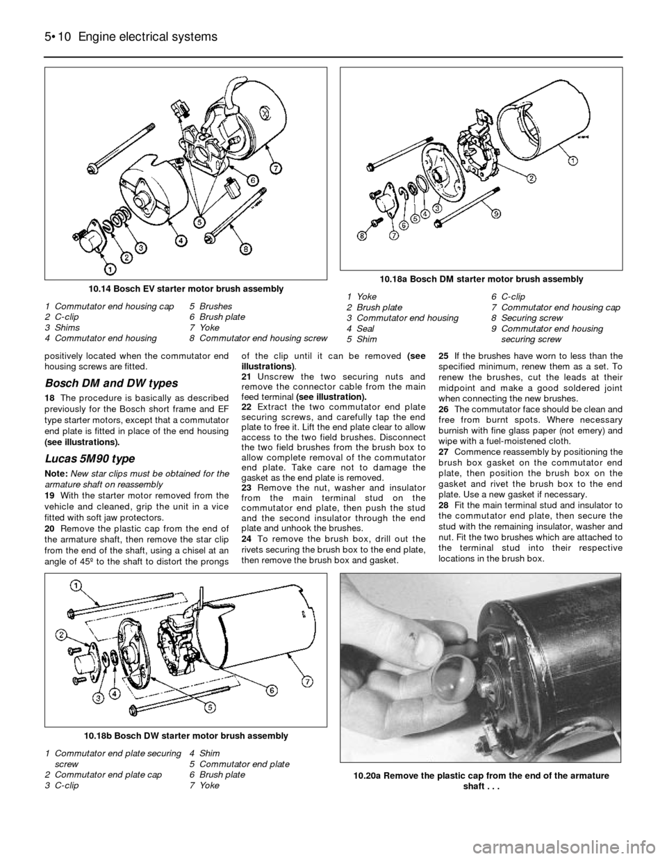
Bosch DM and DW types
18The procedure is basically as described
previously for the Bosch short frame and EF
type starter motors, except that a commutator
end plate is fitted in place of the end housing
(see illustrations).
Lucas 5M90 type
Note: New star clips must be obtained for the
armature shaft on reassembly
19With the starter motor removed from the
vehicle and cleaned, grip the unit in a vice
fitted with soft jaw protectors.
20Remove the plastic cap from the end of
the armature shaft, then remove the star clip
from the end of the shaft, using a chisel at an
angle of 45º to the shaft to distort the prongsof the clip until it can be removed (see
illustrations).
21Unscrew the two securing nuts and
remove the connector cable from the main
feed terminal (see illustration).
22Extract the two commutator end plate
securing screws, and carefully tap the end
plate to free it. Lift the end plate clear to allow
access to the two field brushes. Disconnect
the two field brushes from the brush box to
allow complete removal of the commutator
end plate. Take care not to damage the
gasket as the end plate is removed.
23Remove the nut, washer and insulator
from the main terminal stud on the
commutator end plate, then push the stud
and the second insulator through the end
plate and unhook the brushes.
24To remove the brush box, drill out the
rivets securing the brush box to the end plate,
then remove the brush box and gasket.25If the brushes have worn to less than the
specified minimum, renew them as a set. To
renew the brushes, cut the leads at their
midpoint and make a good soldered joint
when connecting the new brushes.
26The commutator face should be clean and
free from burnt spots. Where necessary
burnish with fine glass paper (not emery) and
wipe with a fuel-moistened cloth.
27Commence reassembly by positioning the
brush box gasket on the commutator end
plate, then position the brush box on the
gasket and rivet the brush box to the end
plate. Use a new gasket if necessary.
28Fit the main terminal stud and insulator to
the commutator end plate, then secure the
stud with the remaining insulator, washer and
nut. Fit the two brushes which are attached to
the terminal stud into their respective
locations in the brush box.
5•10Engine electrical systems
10.18a Bosch DM starter motor brush assembly
1 Yoke
2 Brush plate
3 Commutator end housing
4 Seal
5 Shim6 C-clip
7 Commutator end housing cap
8 Securing screw
9 Commutator end housing
securing screw
10.20a Remove the plastic cap from the end of the armature
shaft . . .
10.18b Bosch DW starter motor brush assembly
1 Commutator end plate securing
screw
2 Commutator end plate cap
3 C-clip4 Shim
5 Commutator end plate
6 Brush plate
7 Yoke
10.14 Bosch EV starter motor brush assembly
1 Commutator end housing cap
2 C-clip
3 Shims
4 Commutator end housing5 Brushes
6 Brush plate
7 Yoke
8 Commutator end housing screw
Page 11 of 24
29Fit the two field brushes into their
locations in the brush box, then position the
commutator end plate on the yoke and fit the
two securing screws.
30Fit a new star clip to the end of the
armature shaft, ensuring that the clip is
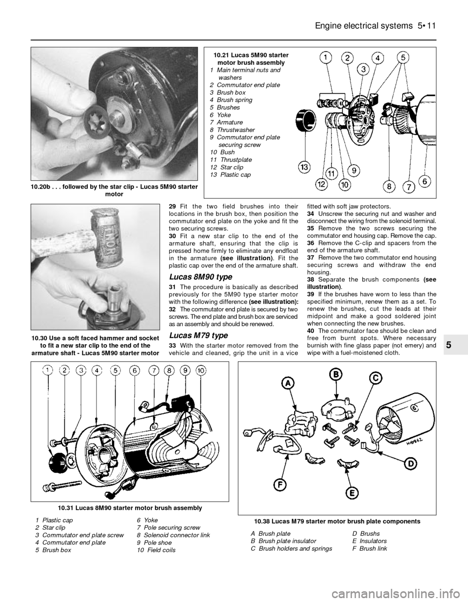
pressed home firmly to eliminate any endfloat
in the armature (see illustration). Fit the
plastic cap over the end of the armature shaft.
Lucas 8M90 type
31The procedure is basically as described
previously for the 5M90 type starter motor
with the following difference(see illustration):
32The commutator end plate is secured by two
screws. The end plate and brush box are serviced
as an assembly and should be renewed.
Lucas M79 type
33With the starter motor removed from the
vehicle and cleaned, grip the unit in a vicefitted with soft jaw protectors.
34Unscrew the securing nut and washer and
disconnect the wiring from the solenoid terminal.
35Remove the two screws securing the
commutator end housing cap. Remove the cap.
36Remove the C-clip and spacers from the
end of the armature shaft.
37Remove the two commutator end housing
securing screws and withdraw the end
housing.
38Separate the brush components (see
illustration).
39If the brushes have worn to less than the
specified minimum, renew them as a set. To
renew the brushes, cut the leads at their
midpoint and make a good soldered joint
when connecting the new brushes.
40The commutator face should be clean and
free from burnt spots. Where necessary
burnish with fine glass paper (not emery) and
wipe with a fuel-moistened cloth.
Engine electrical systems 5•11
5
10.38 Lucas M79 starter motor brush plate components
A Brush plate
B Brush plate insulator
C Brush holders and springsD Brushs
E Insulators
F Brush link
10.31 Lucas 8M90 starter motor brush assembly
1 Plastic cap
2 Star clip
3 Commutator end plate screw
4 Commutator end plate
5 Brush box6 Yoke
7 Pole securing screw
8 Solenoid connector link
9 Pole shoe
10 Field coils
10.30 Use a soft faced hammer and socket
to fit a new star clip to the end of the
armature shaft - Lucas 5M90 starter motor
10.20b . . . followed by the star clip - Lucas 5M90 starter
motor
10.21 Lucas 5M90 starter
motor brush assembly
1 Main terminal nuts and
washers
2 Commutator end plate
3 Brush box
4 Brush spring
5 Brushes
6 Yoke
7 Armature
8 Thrustwasher
9 Commutator end plate
securing screw
10 Bush
11 Thrustplate
12 Star clip
13 Plastic cap
Page 12 of 24
41Locate the brush box over the
commutator, position the brushes, then fit the
nylon cover over the brushes. Route the brush
wiring into the locating channel, then secure
the brushes in the channels with the locking
clips and springs.
42Refit the commutator end housing,
locating the rubber block in the cut-out in the
housing, then secure with the two screws.
43Refit the spacers and C-clip to the end of
the armature shaft, then fit the commutator end
housing cap and secure with the two screws.
44Reconnect the wiring to the solenoid
terminal and fit the washer and securing nut.
Nippondenso type
45With the starter motor removed from the
vehicle and cleaned, grip the unit in a vice
fitted with soft jaw protectors.
46Unscrew the retaining nut and washer and
disconnect the wiring from the terminal on the
solenoid.
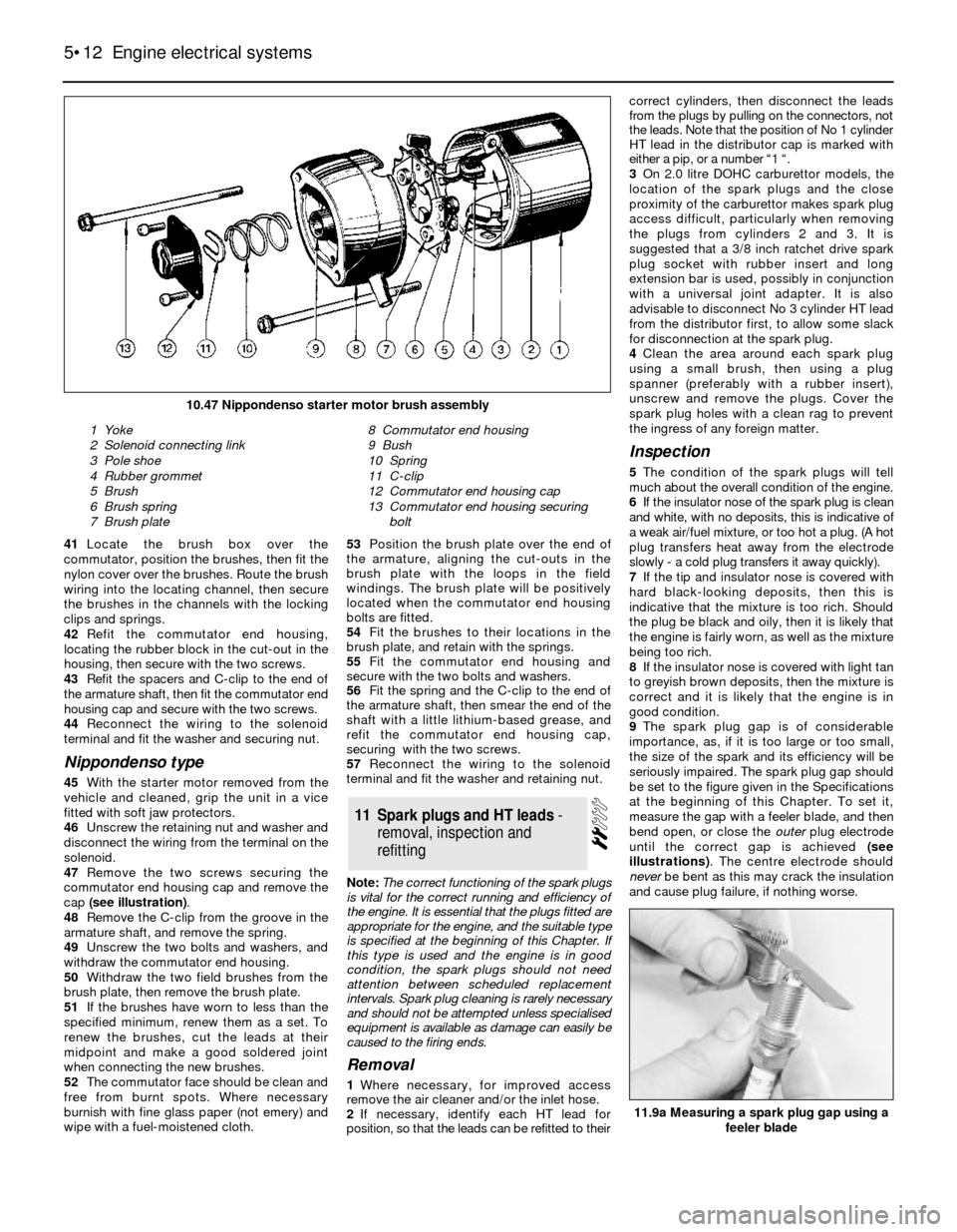
47Remove the two screws securing the
commutator end housing cap and remove the
cap (see illustration).
48Remove the C-clip from the groove in the
armature shaft, and remove the spring.
49Unscrew the two bolts and washers, and
withdraw the commutator end housing.
50Withdraw the two field brushes from the
brush plate, then remove the brush plate.
51If the brushes have worn to less than the
specified minimum, renew them as a set. To
renew the brushes, cut the leads at their
midpoint and make a good soldered joint
when connecting the new brushes.
52The commutator face should be clean and
free from burnt spots. Where necessary
burnish with fine glass paper (not emery) and
wipe with a fuel-moistened cloth. 53Position the brush plate over the end of
the armature, aligning the cut-outs in the
brush plate with the loops in the field
windings. The brush plate will be positively
located when the commutator end housing
bolts are fitted.
54Fit the brushes to their locations in the
brush plate, and retain with the springs.
55Fit the commutator end housing and
secure with the two bolts and washers.
56Fit the spring and the C-clip to the end of
the armature shaft, then smear the end of the
shaft with a little lithium-based grease, and
refit the commutator end housing cap,
securing with the two screws.
57Reconnect the wiring to the solenoid
terminal and fit the washer and retaining nut.
Note: The correct functioning of the spark plugs
is vital for the correct running and efficiency of
the engine. It is essential that the plugs fitted are
appropriate for the engine, and the suitable type
is specified at the beginning of this Chapter. If
this type is used and the engine is in good
condition, the spark plugs should not need
attention between scheduled replacement
intervals. Spark plug cleaning is rarely necessary
and should not be attempted unless specialised
equipment is available as damage can easily be
caused to the firing ends.
Removal
1Where necessary, for improved access
remove the air cleaner and/or the inlet hose.
2If necessary, identify each HT lead for
position, so that the leads can be refitted to theircorrect cylinders, then disconnect the leads
from the plugs by pulling on the connectors, not
the leads. Note that the position of No 1 cylinder
HT lead in the distributor cap is marked with
either a pip, or a number “1 “.
3On 2.0 litre DOHC carburettor models, the
location of the spark plugs and the close
proximity of the carburettor makes spark plug
access difficult, particularly when removing
the plugs from cylinders 2 and 3. It is
suggested that a 3/8 inch ratchet drive spark
plug socket with rubber insert and long
extension bar is used, possibly in conjunction
with a universal joint adapter. It is also
advisable to disconnect No 3 cylinder HT lead
from the distributor first, to allow some slack
for disconnection at the spark plug.
4Clean the area around each spark plug
using a small brush, then using a plug
spanner (preferably with a rubber insert),
unscrew and remove the plugs. Cover the
spark plug holes with a clean rag to prevent
the ingress of any foreign matter.
Inspection
5The condition of the spark plugs will tell
much about the overall condition of the engine.
6If the insulator nose of the spark plug is clean
and white, with no deposits, this is indicative of
a weak air/fuel mixture, or too hot a plug. (A hot
plug transfers heat away from the electrode
slowly - a cold plug transfers it away quickly).
7If the tip and insulator nose is covered with
hard black-looking deposits, then this is
indicative that the mixture is too rich. Should
the plug be black and oily, then it is likely that
the engine is fairly worn, as well as the mixture
being too rich.
8If the insulator nose is covered with light tan
to greyish brown deposits, then the mixture is
correct and it is likely that the engine is in
good condition.
9The spark plug gap is of considerable
importance, as, if it is too large or too small,
the size of the spark and its efficiency will be
seriously impaired. The spark plug gap should
be set to the figure given in the Specifications
at the beginning of this Chapter. To set it,
measure the gap with a feeler blade, and then
bend open, or close the outer plug electrode
until the correct gap is achieved (see
illustrations). The centre electrode should
never be bent as this may crack the insulation
and cause plug failure, if nothing worse.
11Spark plugs and HT leads -
removal, inspection and
refitting
5•12Engine electrical systems
10.47 Nippondenso starter motor brush assembly
1 Yoke
2 Solenoid connecting link
3 Pole shoe
4 Rubber grommet
5 Brush
6 Brush spring
7 Brush plate8 Commutator end housing
9 Bush
10 Spring
11 C-clip
12 Commutator end housing cap
13 Commutator end housing securing
bolt
11.9a Measuring a spark plug gap using a
feeler blade
Page 13 of 24
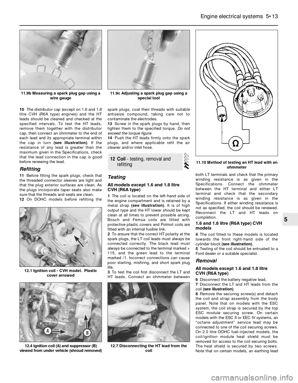
10The distributor cap (except on 1.6 and 1.8
litre CVH (R6A type) engines) and the HT
leads should be cleaned and checked at the
specified intervals. To test the HT leads,
remove them together with the distributor
cap, then connect an ohmmeter to the end of
each lead and its appropriate terminal within
the cap in turn (see illustration). If the
resistance of any lead is greater than the
maximum given in the Specifications, check
that the lead connection in the cap is good
before renewing the lead.
Refitting
11Before fitting the spark plugs, check that
the threaded connector sleeves are tight and
that the plug exterior surfaces are clean. As
the plugs incorporate taper seats also make
sure that the threads and seats are clean.
12On DOHC models before refitting thespark plugs, coat their threads with suitable
antiseize compound, taking care not to
contaminate the electrodes.
13Screw in the spark plugs by hand, then
tighten them to the specified torque. Do not
exceed the torque figure.
14Push the HT leads firmly onto the spark
plugs, and where applicable refit the air
cleaner and/or inlet hose.Testing
All models except 1.6 and 1.8 litre
CVH (R6A type)
1The coil is located on the left-hand side of
the engine compartment and is retained by a
metal strap (see illustration). It is of high
output type and the HT tower should be kept
clean at all times to prevent possible arcing.
Bosch and Femsa coils are fitted with
protective plastic covers and Polmot coils are
fitted with an internal fusible link.
2To ensure that the correct HT polarity at the
spark plugs, the LT coil leads must always be
connected correctly. The black lead must
always be connected to the terminal marked +
115, and the green lead to the terminal
marked /1. Incorrect connections can cause
poor starting, misfiring, and short spark plug
life.
3To test the coil first disconnect the LT and
HT leads. Connect an ohmmeter betweenboth LT terminals and check that the primary
winding resistance is as given in the
Specifications. Connect the ohmmeter
between the HT terminal and either LT
terminal and check that the secondary
winding resistance is as given in the
Specifications. If either winding resistance is
not as specified, the coil should be renewed.
Reconnect the LT and HT leads on
completion.
1.6 and 1.8 litre (R6A type) CVH
models
4The coil fitted to these models is located
towards the front right-hand side of the
cylinder block (see illustration).
5Testing of the coil should be entrusted to a
Ford dealer or a suitable specialist.
Removal
All models except 1.6 and 1.8 litre
CVH (R6A type)
6Disconnect the battery negative lead,
7Disconnect the LT and HT leads from the
coil (see illustration).
8Remove the securing screw(s) and detach
the coil and strap assembly from the body
panel. Note that on models with the ESC
system, the coil strap is secured by the top
ESC module securing screw. On certain
models with the ESC II or EEC IV systems, an
“octane adjustment” service lead may be
connected to one of the coil securing screws.
On 2.0 litre DOHC fuel-injected models, the
coil/ignition module heat shield must be
removed for access to the coil securing bolts.
The heat shield is secured by two screws.
Note that on certain models, an earthing lead
12Coil - testing, removal and
refitting
Engine electrical systems 5•13
5
11.10 Method of testing an HT lead with an
ohmmeter
12.4 Ignition coil (A) and suppressor (B)
viewed from under vehicle (shroud removed)12.7 Disconnecting the HT lead from the
coil
12.1 Ignition coil - CVH model. Plastic
cover arrowed
11.9c Adjusting a spark plug gap using a
special tool11.9b Measuring a spark plug gap using a
wire gauge
Page 14 of 24
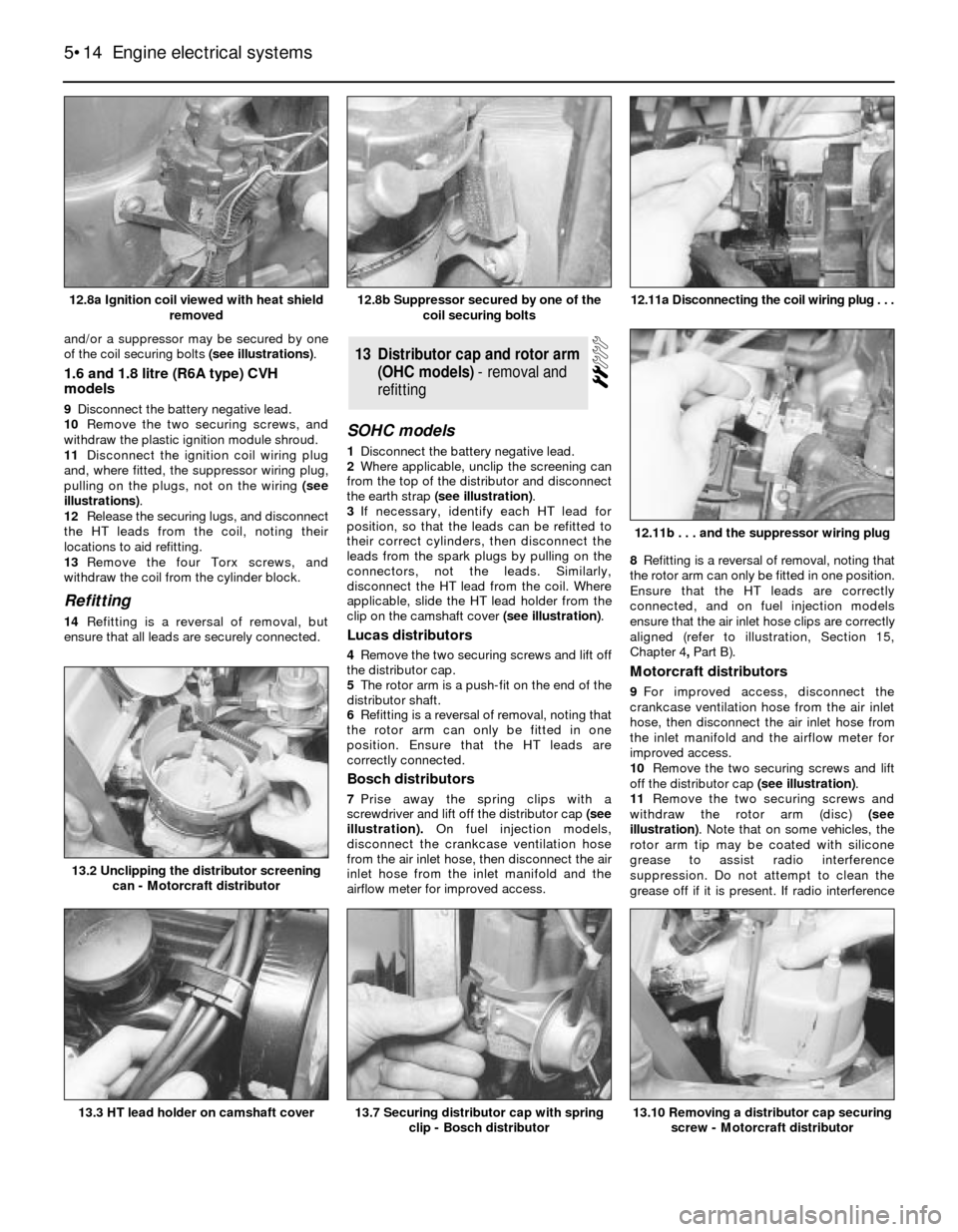
and/or a suppressor may be secured by one
of the coil securing bolts (see illustrations).
1.6 and 1.8 litre (R6A type) CVH
models
9Disconnect the battery negative lead.
10Remove the two securing screws, and
withdraw the plastic ignition module shroud.
11Disconnect the ignition coil wiring plug
and, where fitted, the suppressor wiring plug,
pulling on the plugs, not on the wiring (see
illustrations).
12Release the securing lugs, and disconnect
the HT leads from the coil, noting their
locations to aid refitting.
13Remove the four Torx screws, and
withdraw the coil from the cylinder block.
Refitting
14Refitting is a reversal of removal, but
ensure that all leads are securely connected.
SOHC models
1Disconnect the battery negative lead.
2Where applicable, unclip the screening can
from the top of the distributor and disconnect
the earth strap (see illustration).
3If necessary, identify each HT lead for
position, so that the leads can be refitted to
their correct cylinders, then disconnect the
leads from the spark plugs by pulling on the
connectors, not the leads. Similarly,
disconnect the HT lead from the coil. Where
applicable, slide the HT lead holder from the
clip on the camshaft cover (see illustration).
Lucas distributors
4Remove the two securing screws and lift off
the distributor cap.
5The rotor arm is a push-fit on the end of the
distributor shaft.
6Refitting is a reversal of removal, noting that
the rotor arm can only be fitted in one
position. Ensure that the HT leads are
correctly connected.
Bosch distributors
7Prise away the spring clips with a
screwdriver and lift off the distributor cap(see
illustration).On fuel injection models,
disconnect the crankcase ventilation hose
from the air inlet hose, then disconnect the air
inlet hose from the inlet manifold and the
airflow meter for improved access. 8Refitting is a reversal of removal, noting that
the rotor arm can only be fitted in one position.
Ensure that the HT leads are correctly
connected, and on fuel injection models
ensure that the air inlet hose clips are correctly
aligned (refer to illustration, Section 15,
Chapter 4, PartB).
Motorcraft distributors
9For improved access, disconnect the
crankcase ventilation hose from the air inlet
hose, then disconnect the air inlet hose from
the inlet manifold and the airflow meter for
improved access.
10Remove the two securing screws and lift
off the distributor cap (see illustration).
11Remove the two securing screws and
withdraw the rotor arm (disc) (see
illustration). Note that on some vehicles, the
rotor arm tip may be coated with silicone
grease to assist radio interference
suppression. Do not attempt to clean the
grease off if it is present. If radio interference
13Distributor cap and rotor arm
(OHC models) - removal and
refitting
5•14Engine electrical systems
12.8a Ignition coil viewed with heat shield
removed12.11a Disconnecting the coil wiring plug . . .
13.10 Removing a distributor cap securing
screw - Motorcraft distributor13.7 Securing distributor cap with spring
clip - Bosch distributor13.3 HT lead holder on camshaft cover
13.2 Unclipping the distributor screening
can - Motorcraft distributor
12.11b . . . and the suppressor wiring plug
12.8b Suppressor secured by one of the
coil securing bolts