maintenance schedule FORD SIERRA 1992 2.G Engine Electrical Systems Workshop Manual
[x] Cancel search | Manufacturer: FORD, Model Year: 1992, Model line: SIERRA, Model: FORD SIERRA 1992 2.GPages: 24, PDF Size: 0.93 MB
Page 17 of 24

Refitting
13Commence refitting by checking that No 1
cylinder is still at the firing point. The relevant
timing marks should be aligned. If the engine
has been turned whilst the distributor has
been removed, check that No 1 cylinder is on
its firing stroke by removing the No 1 cylinder
spark plug and placing a finger over the plug
hole. Turn the crankshaft until compression
can be felt, which indicates that No 1 piston is
rising on its firing stroke. Continue turning the
crankshaft until the relevant timing marks are
in alignment.
14Turn the rotor arm to the position noted in
paragraph 11. If a new distributor is being
fitted, and no alignment marks are present,
transfer the marks from the old distributor to
the new distributor.
15Hold the distributor directly over the
aperture in the cylinder block with the
previously made marks on the distributor
body and cylinder block aligned, then lower
the distributor into position. Again, if a new
distributor is being fitted, transfer the
alignment mark from the old distributor body
to the new distributor body. As the skew gear
drive meshes, the rotor arm will turn
anti-clockwise.
16With the distributor fitted and the marks
on the distributor body and cylinder block
aligned, check that the rotor arm is positioned
as described in paragraph 7 -if not, withdraw
the distributor, re-position the driveshaft and
try again.
17Refit the clamp, then insert and tighten
the bolt. Do not fully tighten the bolt at this
stage.
18Refit the distributor wiring plug, and
where applicable reconnect the vacuum pipe,
and refit the dust cover and/or rotor arm.
19Refit the distributor cap, and reconnect
the HT leads to the spark plugs and coil.
Ensure that the leads are refitted to their
correct cylinders.
20Where applicable, refit the screening can
to the top of the distributor and reconnect the
earth strap. On fuel injection models,
reconnect the air inlet hose, ensuring that the
clips are correctly aligned (refer to illustration,
Section 15, Chapter 4, PartB).21Reconnect the battery negative lead.
22Check and if necessary adjust the ignition
timing.
Early “Economy” models
Removal
23Removal of the distributor fitted to these
models is a similar process to that described
above.
Refitting
24Turn the crankshaft to bring No 1 cylinder
to the firing point, with the 16º BTDC mark on
the crankshaft pulley aligned with the pointer
on the crankshaft front oil seal housing, as
described above.
25Fit the new distributor to the engine as
described above, then proceed as follows.
26Cut the original distributor wiring plug
from the wiring loom. Make the cut close to
the connector.
27Strip back 10 mm of insulation from each
of the wires on the wiring loom, and on the
adapter loom supplied with the new
distributor.
28Solder the adapter loom wires to the
corresponding identically coloured wires in
the main loom.
29Carefully insulate each individual soldered
joint using insulating tape, then apply tape to
cover the join between the looms.
30Fit a new distributor cap (and screening
can, where applicable), and connect the HT
leads.31Connect the adapter loom to the
distributor.
32Start the engine, and adjust the ignition
timing to the value given in the Specifications
at the beginning of this Chapter. Work as
described above whilst noting that the
vacuum pipe must be left connected.
Note: During production the ignition timing is
accurately set using a microwave process,
and sealant is applied to the distributor clamp
bolt. Because the electronic components
require no maintenance, checking the ignition
timing does not constitute part of the routine
maintenance schedule, and the procedure is
therefore only necessary after removal and
refitting of the distributor. A timing light will be
required for this procedure. For details of
ignition timing adjustment in order to operate
vehicles on unleaded petrol refer to the
appropriate Section of this Chapter.
All models except 2.0 litre DOHC
1Before checking the ignition timing, the
following conditions must be met:
a)The engine must be at normal operating
temperature
b)Where applicable, the vacuum pipe to the
distributor vacuum unit or electronic
module (as applicable) must be
disconnected from the vacuum unit or
electronic module and plugged
c)The idle speed must be below 900 rpm
(isolate “idle speed adjustment” wire if
necessary)
d)Any earthed “octane adjustment” wires
must be temporarily isolated
2Wipe clean the crankshaft pulley timing
marks and the pointer on the crankshaft front
oil seal housing. Note that two alternative
types of pulley may be fitted (see
illustration).The desired timing values are
given in the Specifications. If necessary, use
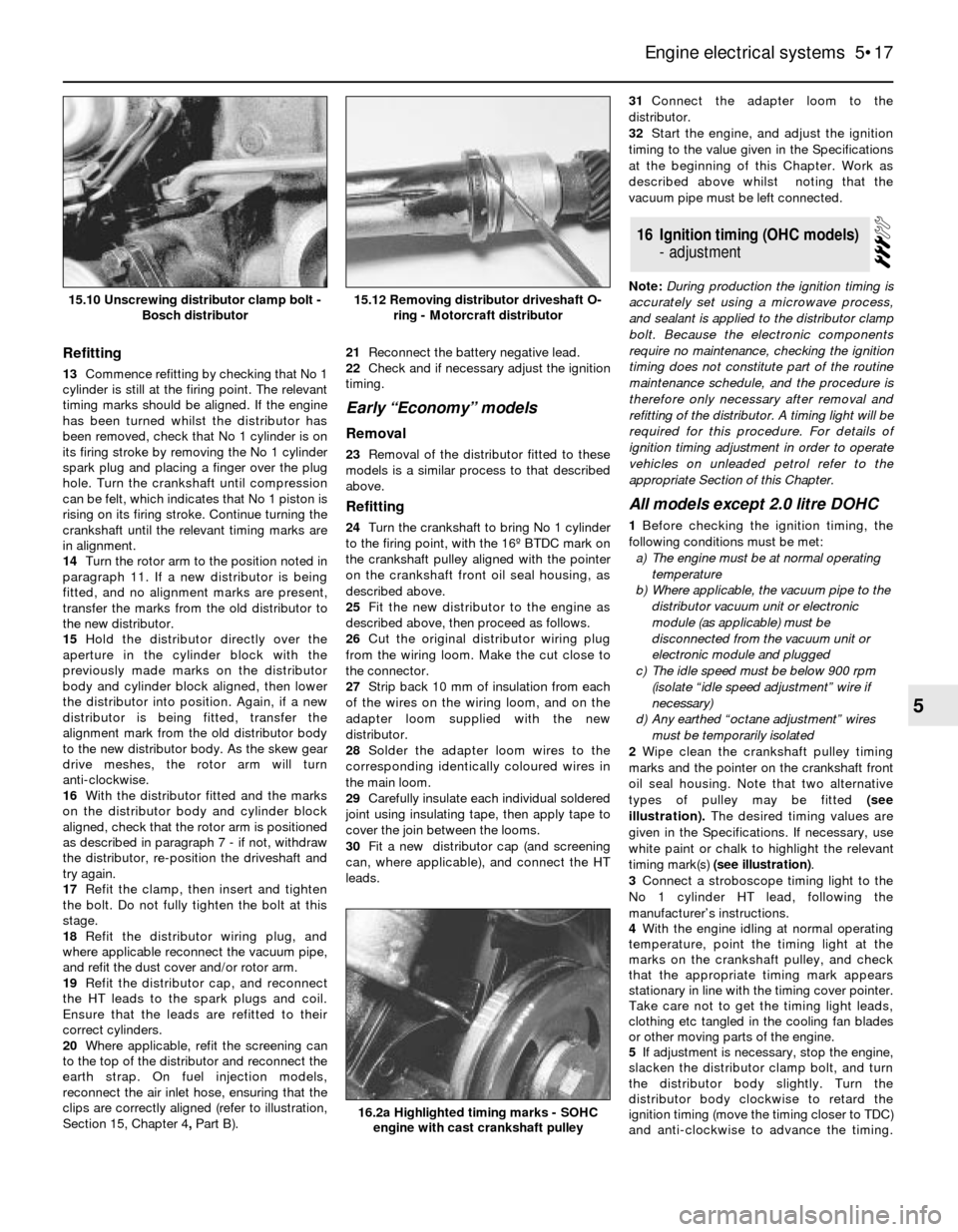
white paint or chalk to highlight the relevant
timing mark(s) (see illustration).
3Connect a stroboscope timing light to the
No 1 cylinder HT lead, following the
manufacturer’s instructions.
4With the engine idling at normal operating
temperature, point the timing light at the
marks on the crankshaft pulley, and check
that the appropriate timing mark appears
stationary in line with the timing cover pointer.
Take care not to get the timing light leads,
clothing etc tangled in the cooling fan blades
or other moving parts of the engine.
5If adjustment is necessary, stop the engine,
slacken the distributor clamp bolt, and turn
the distributor body slightly. Turn the
distributor body clockwise to retard the
ignition timing (move the timing closer to TDC)
and anti-clockwise to advance the timing.
16Ignition timing (OHC models)
- adjustment
Engine electrical systems 5•17
5
15.12 Removing distributor driveshaft O-
ring - Motorcraft distributor15.10 Unscrewing distributor clamp bolt -
Bosch distributor
16.2a Highlighted timing marks - SOHC
engine with cast crankshaft pulley