checking oil FORD SIERRA 1992 2.G Routine Manintenance And Servicing Workshop Manual
[x] Cancel search | Manufacturer: FORD, Model Year: 1992, Model line: SIERRA, Model: FORD SIERRA 1992 2.GPages: 22, PDF Size: 1.26 MB
Page 11 of 22

4Carefully check the condition of all coolant,
fuel, power steering and brake hoses. Renew
any hose which is cracked, swollen or
deteriorated. Cracks will show up better if the
hose is squeezed. Pay close attention to the
hose clips that secure the hoses to the system
components. Hose clips can pinch and
puncture hoses, resulting in leaks. If wire type
hose clips are used, it may be a good idea to
replace them with screw-type clips.
5With the vehicle raised, inspect the fuel
tank and filler neck for punctures, cracks and
other damage. The connection between the
filler neck and tank is especially critical.
Sometimes a rubber filler neck or connecting
hose will leak due to loose retaining clamps or
deteriorated rubber.
6Similarly, inspect all brake hoses and metal
pipes. If any damage or deterioration is
discovered, do not drive the vehicle until the
necessary repair work has been carried out.
Renew any damaged sections of hose or pipe.
7Carefully check all rubber hoses and metal
fuel lines leading away from the petrol tank.
Check for loose connections, deteriorated
hoses, crimped lines and other damage. Pay
particular attention to the vent pipes and
hoses which often loop up around the filler
neck and can become blocked or crimped.
Follow the lines to the front of the vehicle
carefully inspecting them all the way. Renew
damaged sections as necessary.
8From within the engine compartment,
check the security of all fuel hose attachments
and pipe unions, and inspect the fuel hoses
and vacuum hoses for kinks, chafing and
deterioration.
9Where applicable, check the condition of
the oil cooler hoses and pipes.
10Check the condition of all exposed wiring
harnesses.
1Periodically check the belts for fraying or
other damage. If evident, renew the belt.
2If the belts become dirty, wipe them with a
damp cloth using a little detergent only.
3Check the tightness of the anchor bolts and
if they are ever disconnected, make quite sure
that the original sequence of fitting of
washers, bushes and anchor plates is
retained.
With the vehicle raised on a hoist or
supported on axle stands, check the exhaust
system for signs of leaks, corrosion or
damage and check the rubber mountings for
condition and security. Where damage or
corrosion are evident, renew the system
complete or in sections, as applicable, using
the information given in Chapter 4.With the wheels on the ground, slacken each
wheel nut by a quarter turn, then retighten it
immediately to the specified torque.
Remove and clean the oil filler cap of any
sludge build-up using paraffin.
Inspect the vent hose for blockage or
damage. A blocked hose can cause a build-
up of crankcase pressure, which in turn can
cause oil leaks.
Ford VV carburettor
1Ensure that the air cleaner is correctly fitted,
and that all vacuum hoses and pipes are
securely connected and free from restrictions,
then run the engine until it is at normal
operating temperature.
2Stop the engine, and connect a tachometer
and an exhaust gas analyser in accordance
with the manufacturer’s instructions.
3Start the engine and run it at 3000 rpm for
30 seconds, ensuring that all electrical loads
are switched off (headlamps, heater blower
etc), then allow the engine to idle and check
the idle speed and CO content. Note that the
CO reading will initially rise, then fall and finally
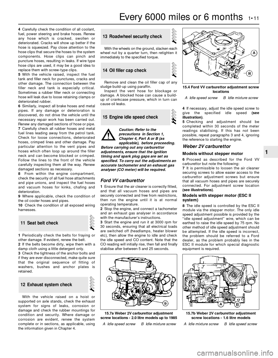
stabilise after between 5 and 25 seconds.4If necessary, adjust the idle speed screw to
give the specified idle speed (see
illustration).
5Checking and adjustment should be
completed within 30 seconds of the meter
readings stabilising. If this has not been
possible, repeat paragraphs 3 and 4, ignoring
the reference to starting the engine.
Weber 2V carburettor
Models without stepper motor
6Proceed as described for the Ford VV
carburettor but note the following:
7It is permissible to loosen the air cleaner
securing screws to allow easier access to the
carburettor adjustment screws but ensure
that all vacuum hoses and pipes are securely
connected. For adjustment screw location
(see illustrations).
Models with stepper motor (ESC II
system)
8The idle speed is controlled by the ESC II
module via the stepper motor. The only idle
speed adjustment possible is provided by the
“idle speed adjustment” wire, which can be
earthed to raise the idle speed by 75 rpm. No
other method of idle speed adjustment should
be attempted. If the idle speed is incorrect,
the problem should be referred to a Ford
dealer, as the problem probably lies in the
ESC II module for which special diagnostic
equipment is required.
15Engine idle speed check
14Oil filler cap check
13Roadwheel security check
12Exhaust system check
11Seat belt check
Every 6000 miles or 6 months 1•11
1
15.7b Weber 2V carburettor adjustment
screw locations - 1.6 litre models
A Idle mixture screwB Idle speed screw
15.7a Weber 2V carburettor adjustment
screw locations - 2.0 litre models up to 1985
A Idle speed screwB Idle mixture screw
15.4 Ford VV carburettor adjustment screw
locations
A Idle speed screwB Idle mixture screw
Caution: Refer to the
precautions in Section 1,
Chapter 4, Part A or B (as
applicable), before proceeding.
Before carrying out any carburettor
adjustments, ensure that the ignition
timing and spark plug gaps are set as
specified. To carry out the adjustments an
accurate tachometer and an exhaust gas
analyser (CO meter) will be required.
Page 13 of 22

25Start the engine and run it at 3000 rpm for
15 seconds, ensuring that all electrical loads
(headlamps, heater blower etc) are switched
off, then allow the engine to idle and check
the CO content. Note that the CO reading will
initially rise, then fall and finally stabilise.
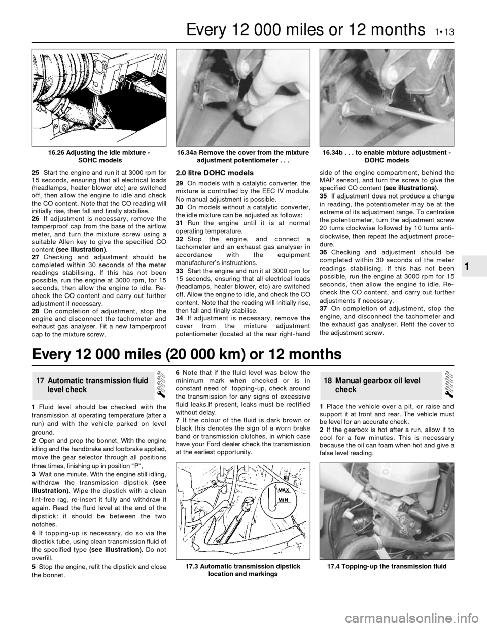
26If adjustment is necessary, remove the
tamperproof cap from the base of the airflow
meter, and turn the mixture screw using a
suitable Allen key to give the specified CO
content (see illustration).
27Checking and adjustment should be
completed within 30 seconds of the meter
readings stabilising. If this has not been
possible, run the engine at 3000 rpm, for 15
seconds, then allow the engine to idle. Re-
check the CO content and carry out further
adjustment if necessary.
28On completion of adjustment, stop the
engine and disconnect the tachometer and
exhaust gas analyser. Fit a new tamperproof
cap to the mixture screw.2.0 litre DOHC models
29On models with a catalytic converter, the
mixture is controlled by the EEC IV module.
No manual adjustment is possible.
30On models without a catalytic converter,
the idle mixture can be adjusted as follows:
31Run the engine until it is at normal
operating temperature.
32Stop the engine, and connect a
tachometer and an exhaust gas analyser in
accordance with the equipment
manufacturer’s instructions.
33Start the engine and run it at 3000 rpm for
15 seconds, ensuring that all electrical loads
(headlamps, heater blower, etc) are switched
off. Allow the engine to idle, and check the CO
content. Note that the reading will initially rise,
then fall and finally stabilise.
34If adjustment is necessary, remove the
cover from the mixture adjustment
potentiometer (located at the rear right-handside of the engine compartment, behind the
MAP sensor), and turn the screw to give the
specified CO content (see illustrations).
35If adjustment does not produce a change
in reading, the potentiometer may be at the
extreme of its adjustment range. To centralise
the potentiometer, turn the adjustment screw
20 turns clockwise followed by 10 turns anti-
clockwise, then repeat the adjustment proce-
dure.
36Checking and adjustment should be
completed within 30 seconds of the meter
readings stabilising. If this has not been
possible, run the engine at 3000 rpm for 15
seconds, then allow the engine to idle. Re-
check the CO content, and carry out further
adjustments if necessary.
37On completion of adjustment, stop the
engine, and disconnect the tachometer and
the exhaust gas analyser. Refit the cover to
the adjustment screw.
1Fluid level should be checked with the
transmission at operating temperature (after a
run) and with the vehicle parked on level
ground.
2Open and prop the bonnet. With the engine
idling and the handbrake and footbrake applied,
move the gear selector through all positions
three times, finishing up in position “P”,
3Wait one minute. With the engine still idling,
withdraw the transmission dipstick (see
illustration).Wipe the dipstick with a clean
lint-free rag, re-insert it fully and withdraw it
again. Read the fluid level at the end of the
dipstick: it should be between the two
notches.
4If topping-up is necessary, do so via the
dipstick tube, using clean transmission fluid of
the specified type (see illustration).Do not
overfill.
5Stop the engine, refit the dipstick and close
the bonnet.6Note that if the fluid level was below the
minimum mark when checked or is in
constant need of topping-up, check around
the transmission for any signs of excessive
fluid leaks.If present, leaks must be rectified
without delay.
7If the colour of the fluid is dark brown or
black this denotes the sign of a worn brake
band or transmission clutches, in which case
have your Ford dealer check the transmission
at the earliest opportunity.1Place the vehicle over a pit, or raise and
support it at front and rear. The vehicle must
be level for an accurate check.
2If the gearbox is hot after a run, allow it to
cool for a few minutes. This is necessary
because the oil can foam when hot and give a
false level reading.
18Manual gearbox oil level
check17Automatic transmission fluid
level check
Every 12 000 miles or 12 months 1•13
1
16.34b . . . to enable mixture adjustment -
DOHC models
17.4 Topping-up the transmission fluid17.3 Automatic transmission dipstick
location and markings
16.34a Remove the cover from the mixture
adjustment potentiometer . . .16.26 Adjusting the idle mixture -
SOHC models
Every 12 000 miles (20 000 km) or 12 months
Page 16 of 22

5Numbering from the front (camshaft
sprocket) end of the engine, the exhaust
valves are 1, 3, 5 and 7, and the inlet valves
are 2, 4, 6 and 8.
6Turn the engine clockwise using a suitable
socket on the crankshaft pulley bolt, until the
exhaust valve of No 1 cylinder (valve No 1) is
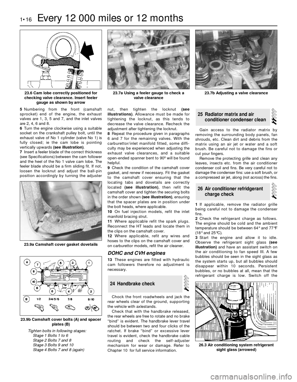
fully closed; ie the cam lobe is pointing
vertically upwards (see illustration).
7Insert a feeler blade of the correct thickness
(see Specifications) between the cam follower
and the heel of the No 1 valve cam lobe. The
feeler blade should be a firm sliding fit. If not,
loosen the locknut and adjust the ball-pin
position accordingly by turning the adjusternut, then tighten the locknut (see
illustrations). Allowance must be made for
tightening the locknut, as this tends to
decrease the valve clearance. Recheck the
adjustment after tightening the locknut.
8Repeat the procedure given in paragraphs
6 and 7 for the remaining valves. With the
carburettor/inlet manifold fitted, some diffi-
culty may be experienced when adjusting the
exhaust valve clearances, and a suitable
open-ended spanner bent to 90º will be found
helpful.
9Check the condition of the camshaft cover
gasket, and renew if necessary. Fit the gasket
to the camshaft cover ensuring that the
locating tabs and dovetails are correctly
located (see illustration), then refit the
camshaft cover and tighten the securing bolts
in the order shown (see illustration), ensuring
that the spacer plates are in position under
the bolt heads, where applicable.
10On fuel injection models, refit the inlet
manifold bracing strut.
11Where applicable refit the spark plugs.
Reconnect the HT leads and locate them in
the clips on the camshaft cover.
12Where applicable, refit any wires and
hoses to the clips on the camshaft cover and
on carburettor models, refit the air cleaner.
DOHCand CVH engines
13These engines are fitted with hydraulic
cam followers therefore no adjustment is
necessary.
Chock the front roadwheels and jack the
rear wheels clear of the ground, supporting
the vehicle with axlestands.
Check that with the handbrake released,
the rear wheels are free to rotate and no brake
“bind” is evident. The handbrake lever travel
should be between two and four clicks of the
ratchet. If brake “bind” or excessive lever
travel is evident, check the handbrake cable
routing and check the self-adjuster
mechanism for wear or damage. Refer to
Chapter 10 for full service information. Gain access to the radiator matrix by
removing the surrounding body panels, fan
shrouds, etc. Clean dirt and debris from the
matrix using an air jet or water and a soft
brush. Be careful not to damage the fins or
cut your fingers.
Remove the protecting grille and clean any
leaves, insects etc. from the air conditioner
condenser coil and fins. Be very careful not to
damage the condenser fins: use a soft brush, or
a compressed air jet, along (not across) the fins.
1If applicable, remove the radiator grille
being careful not to damage the condenser
fins.
2Check the refrigerant charge as follows.
The engine should be cold and the ambient
temperature should be between 64°and 77°F
(18°and 25°C).
3Start the engine and allow it to idle.
Observe the refrigerant sight glass(see
illustration)and have an assistant switch on
the air conditioning to fan speed III. A few
bubbles should be seen in the sight glass as
the system starts up, but all bubbles should
disappear within 10 seconds. Persistent
bubbles, or no bubbles at all, mean that the
refrigerant charge is low. Switch off the
26Air conditioner refridgerant
charge check
25Radiator matrix and air
conditioner condenser clean
24Handbrake check
1•16Every 12 000 miles or 12 months
23.6 Cam lobe correctly positioned for
checking valve clearance. Insert feeler
gauge as shown by arrow23.7b Adjusting a valve clearance
26.3 Air conditioning system refrigerant
sight glass (arrowed)
23.9b Camshaft cover bolts (A) and spacer
plates (B)
Tighten bolts in following stages:
Stage 1 Bolts 1 to 6
Stage 2 Bolts 7 and 8
Stage 3 Bolts 9 and 10
Stage 4 Bolts 7 and 8 (again)
23.9a Camshaft cover gasket dovetails
23.7a Using a feeler gauge to check a
valve clearance