ignition FORD SIERRA 1992 2.G SOHC Engines Workshop Manual
[x] Cancel search | Manufacturer: FORD, Model Year: 1992, Model line: SIERRA, Model: FORD SIERRA 1992 2.GPages: 24, PDF Size: 1.03 MB
Page 7 of 24
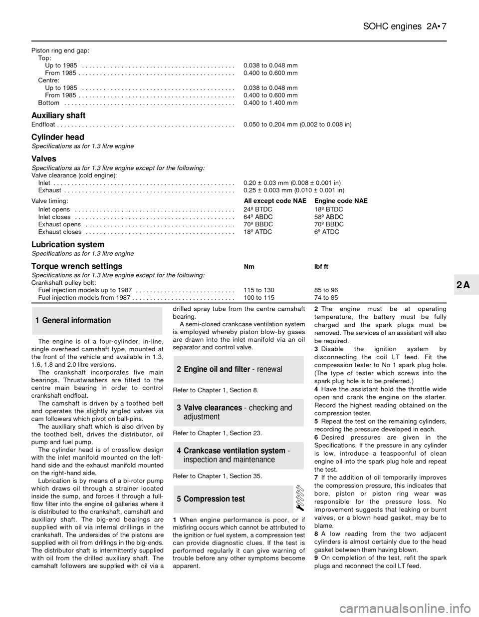
Piston ring end gap:
Top:
Up to 1985 . . . . . . . . . . . . . . . . . . . . . . . . . . . . . . . . . . . . . . . . . . .0.038 to 0.048 mm
From 1985 . . . . . . . . . . . . . . . . . . . . . . . . . . . . . . . . . . . . . . . . . . . .0.400 to 0.600 mm
Centre:
Up to 1985 . . . . . . . . . . . . . . . . . . . . . . . . . . . . . . . . . . . . . . . . . . .0.038 to 0.048 mm
From 1985 . . . . . . . . . . . . . . . . . . . . . . . . . . . . . . . . . . . . . . . . . . . .0.400 to 0.600 mm
Bottom . . . . . . . . . . . . . . . . . . . . . . . . . . . . . . . . . . . . . . . . . . . . . . . .0.400 to 1.400 mm
Auxiliary shaft
Endfloat . . . . . . . . . . . . . . . . . . . . . . . . . . . . . . . . . . . . . . . . . . . . . . . . . .0.050 to 0.204 mm (0.002 to 0.008 in)
Cylinder head
Specifications as for 1.3 litre engine
Valves
Specifications as for 1.3 litre engine except for the following:
Valve clearance (cold engine):
Inlet . . . . . . . . . . . . . . . . . . . . . . . . . . . . . . . . . . . . . . . . . . . . . . . . . . .0.20 ±0.03 mm (0.008 ±0.001 in)
Exhaust . . . . . . . . . . . . . . . . . . . . . . . . . . . . . . . . . . . . . . . . . . . . . . . .0.25 ±0.003 mm (0.010 ±0.001 in)
Valve timing:All except code NAEEngine code NAE
Inlet opens . . . . . . . . . . . . . . . . . . . . . . . . . . . . . . . . . . . . . . . . . . . . .24¼ BTDC18¼ BTDC
Inlet closes . . . . . . . . . . . . . . . . . . . . . . . . . . . . . . . . . . . . . . . . . . . . .64¼ ABDC58¼ ABDC
Exhaust opens . . . . . . . . . . . . . . . . . . . . . . . . . . . . . . . . . . . . . . . . . .70¼ BBDC70¼ BBDC
Exhaust closes . . . . . . . . . . . . . . . . . . . . . . . . . . . . . . . . . . . . . . . . . .18¼ ATDC6¼ ATDC
Lubrication system
Specifications as for 1.3 litre engine
Torque wrench settingsNmlbf ft
Specifications as for 1.3 litre engine except for the following:
Crankshaft pulley bolt:
Fuel injection models up to 1987 . . . . . . . . . . . . . . . . . . . . . . . . . . . .115 to 13085 to 96
Fuel injection models from 1987 . . . . . . . . . . . . . . . . . . . . . . . . . . . . .100 to 11574 to 85
SOHC engines 2A¥7
2A
The engine is of a four-cylinder, in-line,
single overhead camshaft type, mounted at
the front of the vehicle and available in 1.3,
1.6, 1.8 and 2.0 litre versions.
The crankshaft incorporates five main
bearings. Thrustwashers are fitted to the
centre main bearing in order to control
crankshaft endfloat.
The camshaft is driven by a toothed belt
and operates the slightly angled valves via
cam followers which pivot on ball-pins.
The auxiliary shaft which is also driven by
the toothed belt, drives the distributor, oil
pump and fuel pump.
The cylinder head is of crossflow design
with the inlet manifold mounted on the left-
hand side and the exhaust manifold mounted
on the right-hand side.
Lubrication is by means of a bi-rotor pump
which draws oil through a strainer located
inside the sump, and forces it through a full-
flow filter into the engine oil galleries where it
is distributed to the crankshaft, camshaft and
auxiliary shaft. The big-end bearings are
supplied with oil via internal drillings in the
crankshaft. The undersides of the pistons are
supplied with oil from drillings in the big-ends.
The distributor shaft is intermittently supplied
with oil from the drilled auxiliary shaft. The
camshaft followers are supplied with oil via adrilled spray tube from the centre camshaft
bearing.
A semi-closed crankcase ventilation system
is employed whereby piston blow-by gases
are drawn into the inlet manifold via an oil
separator and control valve.
Refer to Chapter 1, Section 8.
Refer to Chapter 1, Section 23.
Refer to Chapter 1, Section 35.
1When engine performance is poor, or if
misfiring occurs which cannot be attributed to
the ignition or fuel system, a compression test
can provide diagnostic clues. If the test is
performed regularly it can give warning of
trouble before any other symptoms become
apparent.2The engine must be at operating
temperature, the battery must be fully
charged and the spark plugs must be
removed. The services of an assistant will also
be required.
3Disable the ignition system by
disconnecting the coil LT feed. Fit the
compression tester to No 1 spark plug hole.
(The type of tester which screws into the
spark plug hole is to be preferred.)
4Have the assistant hold the throttle wide
open and crank the engine on the starter.
Record the highest reading obtained on the
compression tester.
5Repeat the test on the remaining cylinders,
recording the pressure developed in each.
6Desired pressures are given in the
Specifications. If the pressure in any cylinder
is low, introduce a teaspoonful of clean
engine oil into the spark plug hole and repeat
the test.
7If the addition of oil temporarily improves
the compression pressure, this indicates that
bore, piston or piston ring wear was
responsible for the pressure loss. No
improvement suggests that leaking or burnt
valves, or a blown head gasket, may be to
blame.
8A low reading from the two adjacent
cylinders is almost certainly due to the head
gasket between them having blown.
9On completion of the test, refit the spark
plugs and reconnect the coil LT feed.
5Compression test
4Crankcase ventilation system -
inspection and maintenance
3Valve clearances - checking and
adjustment
2Engine oil and filter - renewal
1General information
Page 8 of 24
The following operations can be carried out
without removing the engine from the vehicle:
a)Removal and servicing of the cylinder
head
b)Removal of the camshaft after removal of
the cylinder head
c)Removal of the timing belt and sprockets
d)Removal of the sump
e)Removal of the oil pump
f)Removal of the pistons and connecting
rods
g)Removal of the big-end bearings
h)Removal of the engine mountings
i)Removal of the clutch and flywheel
j)Removal of crankshaft front and rear oil
seals
k)Removal of the auxiliary shaft
The following operations can only be carried
out after removing the engine from the
vehicle:
a)Removal of the crankshaft main bearings
b)Removal of the crankshaft
The engine may be lifted out either on its
own, or together with the manual
gearbox/automatic transmission. Unless work
is to be carried out on the manual
gearbox/automatic transmission, it is
recommended that the engine is removed on
its own. Where automatic transmission is
fitted, the engine should where possible be
removed on its own due to the additional
weight of the transmission. Note: The air conditioning system should
always be discharged by a Ford dealer or air
conditioning specialist.
Note: Refer to the warning in Section 8 before
proceeding. A suitable hoist and lifting tackle
will be required for this operation.
1Disconnect the battery negative lead.
2Remove the bonnet.
3On carburettor models remove the air cleaner.
4On fuel injection models, disconnect the
crankcase ventilation hose from the air inlet
hose, then disconnect the air inlet hose from
the throttle body. Depress the locking clip on
the airflow meter wiring plug and disconnect
the plug (pulling on the plug, not the wiring)
then release the four securing clips and lift off
the air cleaner lid with the airflow meter and
air inlet hose.
5Remove the four retaining clips and
unscrew the two retaining screws, then
withdraw the upper section of the cooling fan
shroud from the radiator. Unclip and remove
the lower section of the shroud.
6Remove the thermo-viscous cooling fan as
described in Chapter 3.
7Drain the cooling system.
8Disconnect the upper radiator hose and
where applicable, the expansion tank hose
from the thermostat housing.
9Disconnect the coolant hoses from the
coolant pump, and where applicable from the
inlet manifold and automatic choke. Unclip
the coolant hose from the bracket on the
exhaust manifold hot air shroud/heat shield,
or the camshaft cover, as applicable.
10On carburettor models, where applicable
disconnect the vacuum pipe from the engine
management module.
11Disconnect the brake servo vacuum pipe
from the inlet manifold.
12On carburettor models, disconnect the fuel
hoses from the carburettor and where
applicable the mechanical fuel pump and plug
the ends of the hoses to minimise petrol
spillage. Remember to take adequate fire
precautions.
13On fuel injection models, disconnect the
fuel feed line from the fuel pressure regulator,
then disconnect the fuel supply hose from thefuel rail. Position a suitable container beneath
the pressure regulator, then slowly loosen the
fuel feed union to relieve the pressure in the
fuel lines before disconnecting the union.
Take adequate fire precautions. Plug the ends
of the hoses to minimise petrol spillage.
14Disconnect the throttle cable, and where
applicable remove its bracket.
15Disconnect the HT lead from the ignition
coil.
16Disconnect the wiring from the following
components as applicable depending on
model:
Alternator
Starter motor
Distributor
Oil pressure warning lamp switch
Temperature gauge sender
Engine coolant temperature sensor
Automatic choke
Automatic choke pull-down solenoid
Carburettor anti-dieselling valve
Inlet manifold heater
Carburettor stepper motor
Fuel injection harness
Dipstick
17Where applicable, detach the power
steering pump from the cylinder block and
move it to one side.
18Unscrew and remove the top engine-to-
gearbox bolts which are accessible from the
engine compartment. Note the location of the
earth strap on one of the bolts.
19Note the location of the earth strap on the
rear inlet manifold stud, then remove the nut
and disconnect the strap.
20Apply the handbrake (if not already done),
jack up the front of the vehicle and support on
axle stands (see ÒJacking and Vehicle SupportÓ).
21Drain the engine oil into a suitable
container.
22Remove the starter motor.
23Remove the exhaust downpipe.
24Unscrew the nuts or bolts, as applicable,
securing the engine mountings to the
crossmember. Recover the washers.
25Unscrew and remove the remaining
engine-to-gearbox bolts, and remove the bolt
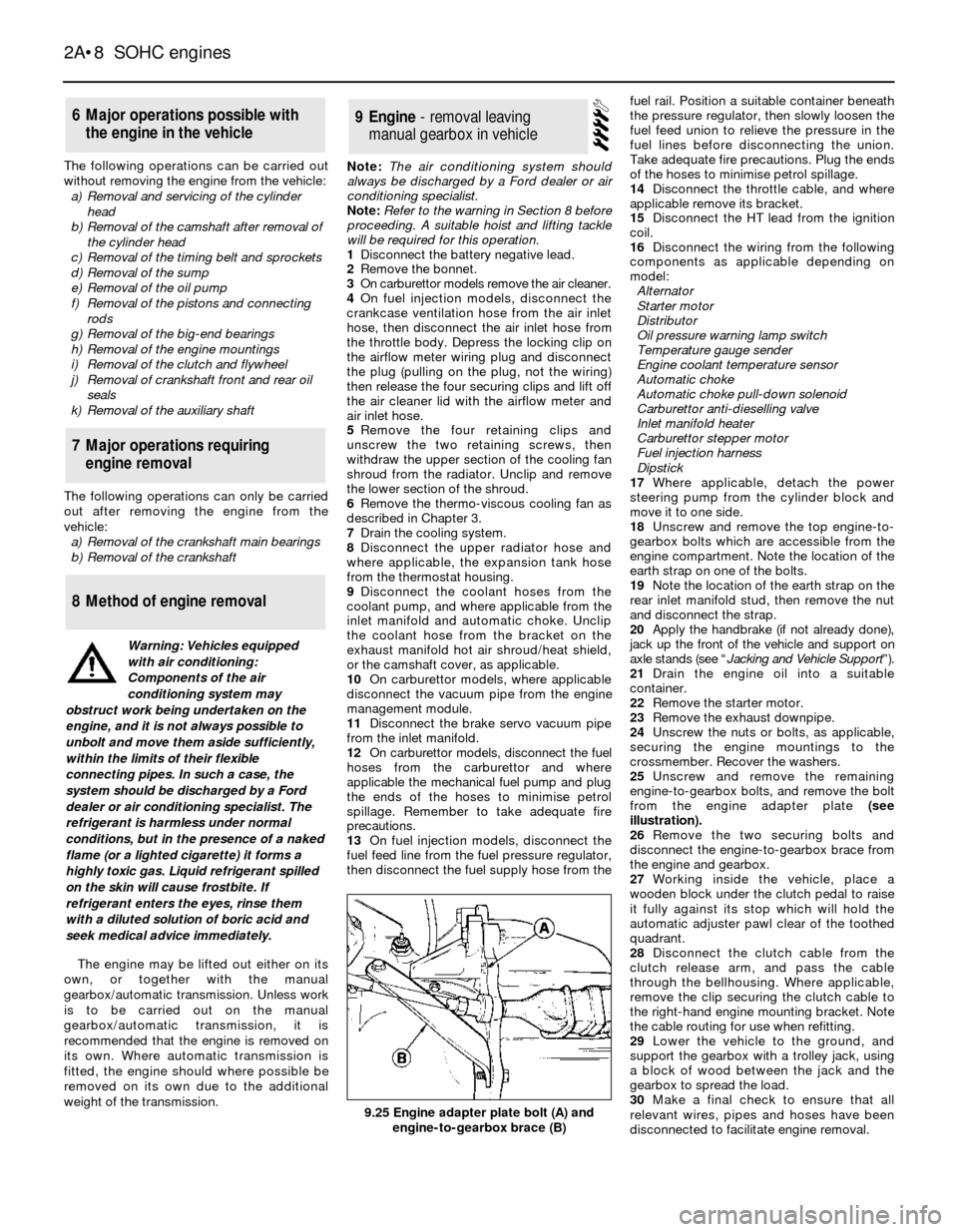
from the engine adapter plate (see
illustration).
26Remove the two securing bolts and
disconnect the engine-to-gearbox brace from
the engine and gearbox.
27Working inside the vehicle, place a
wooden block under the clutch pedal to raise
it fully against its stop which will hold the
automatic adjuster pawl clear of the toothed
quadrant.
28Disconnect the clutch cable from the
clutch release arm, and pass the cable
through the bellhousing. Where applicable,
remove the clip securing the clutch cable to
the right-hand engine mounting bracket. Note
the cable routing for use when refitting.
29Lower the vehicle to the ground, and
support the gearbox with a trolley jack, using
a block of wood between the jack and the
gearbox to spread the load.
30Make a final check to ensure that all
relevant wires, pipes and hoses have been
disconnected to facilitate engine removal.
9Engine - removal leaving
manual gearbox in vehicle
8Method of engine removal
7Major operations requiring
engine removal
6Major operations possible with
the engine in the vehicle
2A¥8SOHC engines
9.25 Engine adapter plate bolt (A) and
engine-to-gearbox brace (B)
Warning: Vehicles equipped
with air conditioning:
Components of the air
conditioning system may
obstruct work being undertaken on the
engine, and it is not always possible to
unbolt and move them aside sufficiently,
within the limits of their flexible
connecting pipes. In such a case, the
system should be discharged by a Ford
dealer or air conditioning specialist. The
refrigerant is harmless under normal
conditions, but in the presence of a naked
flame (or a lighted cigarette) it forms a
highly toxic gas. Liquid refrigerant spilled
on the skin will cause frostbite. If
refrigerant enters the eyes, rinse them
with a diluted solution of boric acid and
seek medical advice immediately.
Page 14 of 24
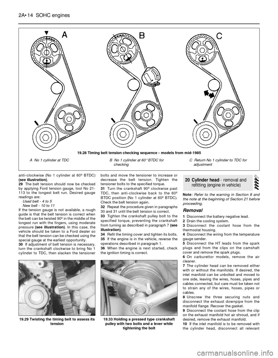
anti-clockwise (No 1 cylinder at 60¼ BTDC)
(see illustration).
29The belt tension should now be checked
by applying Ford tension gauge, tool No 21-
113 to the longest belt run. Desired gauge
readings are:
Used belt - 4 to 5
New belt - 10 to 11
If the tension gauge is not available, a rough
guide is that the belt tension is correct when
the belt can be twisted 90¼ in the middle of the
longest run with the fingers, using moderate
pressure (see illustration). In this case, the
vehicle should be taken to a Ford dealer so
that the belt tension can be checked using the
special gauge at the earliest opportunity.
30If adjustment of belt tension is necessary,
turn the crankshaft clockwise to bring No 1
cylinder to TDC, then slacken the tensionerbolts and move the tensioner to increase or
decrease the belt tension. Tighten the
tensioner bolts to the specified torque.
31Turn the crankshaft 90¼ clockwise past
TDC, then anti-clockwise back to the 60¼
BTDC position (No 1 cylinder at 60¼ BTDC).
Check the belt tension again.
32Repeat the procedure given in paragraphs
30 and 31 until the belt tension is correct.
33Tighten the crankshaft pulley bolt to the
specified torque, preventing the crankshaft
from turning as described in paragraph 7 (see
illustration).
34Refit the timing cover and tighten its bolts.
35If the engine is in the vehicle, reverse the
operations described in paragraph 1.
36When the engine is next started, check
the ignition timing is correct.Note: Refer to the warning in Section 8 and
the note at the beginning of Section 21 before
proceeding.
Removal
1Disconnect the battery negative lead.
2Drain the cooling system.
3Disconnect the coolant hose from the
thermostat housing.
4Disconnect the wiring from the temperature
gauge sender.
5Disconnect the HT leads from the spark
plugs and from the clips on the camshaft
cover and remove the spark plugs.
6On carburettor models, remove the air
cleaner.
7The cylinder head can be removed either
with or without the manifolds. If desired, the
inlet manifold can be unbolted and moved to
one side, leaving the wires, hoses, pipes and
cables connected, but care must be taken not
to strain any of the wires, hoses, pipes or
cables.
8Unscrew the three securing nuts and
disconnect the exhaust downpipe from the
manifold flange. Recover the gasket.
9Disconnect the coolant hose from the clip
on the exhaust manifold hot air shroud, and if
desired, remove the exhaust manifold.
10If the inlet manifold is to be removed with
the cylinder head, disconnect all relevant
20Cylinder head - removal and
refitting (engine in vehicle)
2A¥14SOHC engines
19.33 Holding a pressed type crankshaft
pulley with two bolts and a lever while
tightening the bolt19.29 Twisting the timing belt to assess its
tension
19.28 Timing belt tension checking sequence - models from mid-1985
A No 1 cylinder at TDCB No 1 cylinder at 60¡BTDC for
checkingC Return No 1 cylinder to TDC for
adjustment
Page 16 of 24
Note: A valve spring compressor will be
required during this procedure. New valve
stem oil seals should be used on reassembly.
Dismantling
1With the cylinder head removed, remove
the camshaft.
2Using a valve spring compressor, compress
one of the valve springs until the split collets
can be removed from the groove in the valve
stem. Release the compressor and remove
the cap and spring, identifying them for
location. If the cap is difficult to release, do
not continue to tighten the compressor, but
gently tap the top of the tool with a hammer.
Always make sure that the compressor is
firmly located on the valve head and the cap.
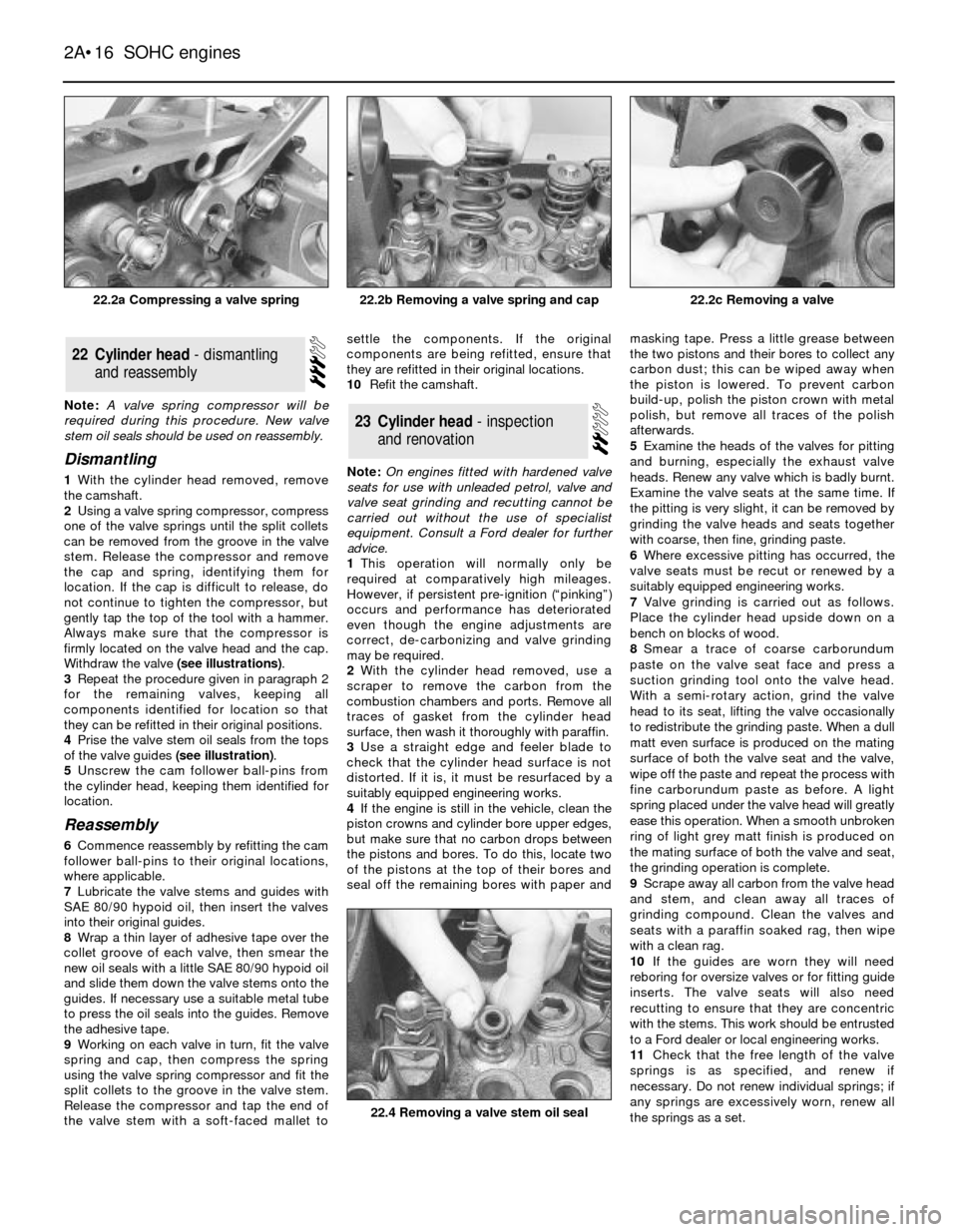
Withdraw the valve (see illustrations).
3Repeat the procedure given in paragraph 2
for the remaining valves, keeping all
components identified for location so that
they can be refitted in their original positions.
4Prise the valve stem oil seals from the tops
of the valve guides (see illustration).
5Unscrew the cam follower ball-pins from
the cylinder head, keeping them identified for
location.
Reassembly
6Commence reassembly by refitting the cam
follower ball-pins to their original locations,
where applicable.
7Lubricate the valve stems and guides with
SAE 80/90 hypoid oil, then insert the valves
into their original guides.
8Wrap a thin layer of adhesive tape over the
collet groove of each valve, then smear the
new oil seals with a little SAE 80/90 hypoid oil
and slide them down the valve stems onto the
guides. If necessary use a suitable metal tube
to press the oil seals into the guides. Remove
the adhesive tape.
9Working on each valve in turn, fit the valve
spring and cap, then compress the spring
using the valve spring compressor and fit the
split collets to the groove in the valve stem.
Release the compressor and tap the end of
the valve stem with a soft-faced mallet tosettle the components. If the original
components are being refitted, ensure that
they are refitted in their original locations.
10Refit the camshaft.
Note: On engines fitted with hardened valve
seats for use with unleaded petrol, valve and
valve seat grinding and recutting cannot be
carried out without the use of specialist
equipment. Consult a Ford dealer for further
advice.
1This operation will normally only be
required at comparatively high mileages.
However, if persistent pre-ignition (ÒpinkingÓ)
occurs and performance has deteriorated
even though the engine adjustments are
correct, de-carbonizing and valve grinding
may be required.
2With the cylinder head removed, use a
scraper to remove the carbon from the
combustion chambers and ports. Remove all
traces of gasket from the cylinder head
surface, then wash it thoroughly with paraffin.
3Use a straight edge and feeler blade to
check that the cylinder head surface is not
distorted. If it is, it must be resurfaced by a
suitably equipped engineering works.
4If the engine is still in the vehicle, clean the
piston crowns and cylinder bore upper edges,
but make sure that no carbon drops between
the pistons and bores. To do this, locate two
of the pistons at the top of their bores and
seal off the remaining bores with paper andmasking tape. Press a little grease between
the two pistons and their bores to collect any
carbon dust; this can be wiped away when
the piston is lowered. To prevent carbon
build-up, polish the piston crown with metal
polish, but remove all traces of the polish
afterwards.
5Examine the heads of the valves for pitting
and burning, especially the exhaust valve
heads. Renew any valve which is badly burnt.
Examine the valve seats at the same time. If
the pitting is very slight, it can be removed by
grinding the valve heads and seats together
with coarse, then fine, grinding paste.
6Where excessive pitting has occurred, the
valve seats must be recut or renewed by a
suitably equipped engineering works.
7Valve grinding is carried out as follows.
Place the cylinder head upside down on a
bench on blocks of wood.
8Smear a trace of coarse carborundum
paste on the valve seat face and press a
suction grinding tool onto the valve head.
With a semi-rotary action, grind the valve
head to its seat, lifting the valve occasionally
to redistribute the grinding paste. When a dull
matt even surface is produced on the mating
surface of both the valve seat and the valve,
wipe off the paste and repeat the process with
fine carborundum paste as before. A light
spring placed under the valve head will greatly
ease this operation. When a smooth unbroken
ring of light grey matt finish is produced on
the mating surface of both the valve and seat,
the grinding operation is complete.
9Scrape away all carbon from the valve head
and stem, and clean away all traces of
grinding compound. Clean the valves and
seats with a paraffin soaked rag, then wipe
with a clean rag.
10If the guides are worn they will need
reboring for oversize valves or for fitting guide
inserts. The valve seats will also need
recutting to ensure that they are concentric
with the stems. This work should be entrusted
to a Ford dealer or local engineering works.
11Check that the free length of the valve
springs is as specified, and renew if
necessary. Do not renew individual springs; if
any springs are excessively worn, renew all
the springs as a set.
23Cylinder head - inspection
and renovation
22Cylinder head - dismantling
and reassembly
2A¥16SOHC engines
22.2a Compressing a valve spring22.2c Removing a valve
22.4 Removing a valve stem oil seal
22.2b Removing a valve spring and cap
Page 24 of 24
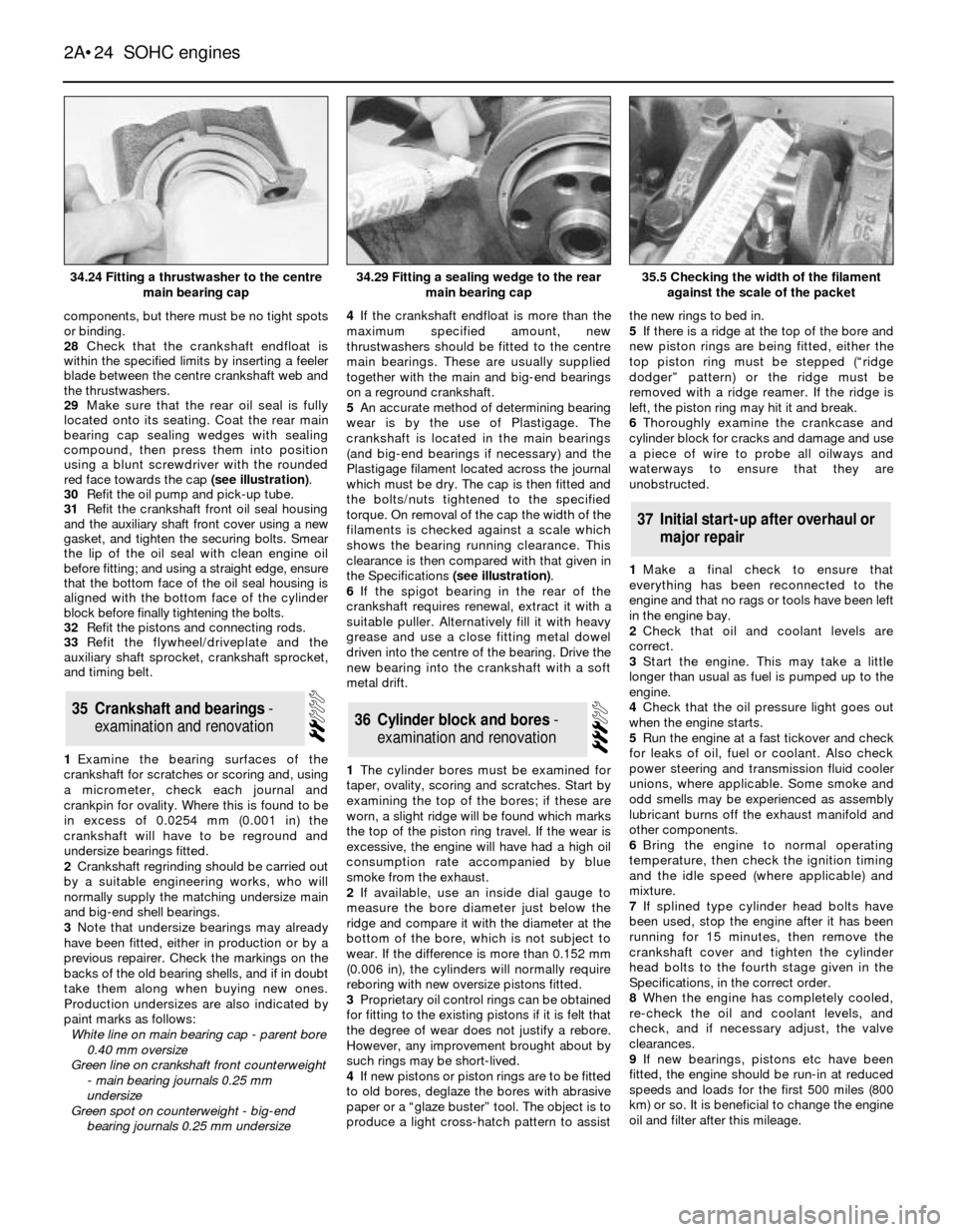
components, but there must be no tight spots
or binding.
28Check that the crankshaft endfloat is
within the specified limits by inserting a feeler
blade between the centre crankshaft web and
the thrustwashers.
29Make sure that the rear oil seal is fully
located onto its seating. Coat the rear main
bearing cap sealing wedges with sealing
compound, then press them into position
using a blunt screwdriver with the rounded
red face towards the cap (see illustration).
30Refit the oil pump and pick-up tube.
31Refit the crankshaft front oil seal housing
and the auxiliary shaft front cover using a new
gasket, and tighten the securing bolts. Smear
the lip of the oil seal with clean engine oil
before fitting; and using a straight edge, ensure
that the bottom face of the oil seal housing is
aligned with the bottom face of the cylinder
block before finally tightening the bolts.
32Refit the pistons and connecting rods.
33Refit the flywheel/driveplate and the
auxiliary shaft sprocket, crankshaft sprocket,
and timing belt.
1Examine the bearing surfaces of the
crankshaft for scratches or scoring and, using
a micrometer, check each journal and
crankpin for ovality. Where this is found to be
in excess of 0.0254 mm (0.001 in) the
crankshaft will have to be reground and
undersize bearings fitted.
2Crankshaft regrinding should be carried out
by a suitable engineering works, who will
normally supply the matching undersize main
and big-end shell bearings.
3Note that undersize bearings may already
have been fitted, either in production or by a
previous repairer. Check the markings on the
backs of the old bearing shells, and if in doubt
take them along when buying new ones.
Production undersizes are also indicated by
paint marks as follows:
White line on main bearing cap - parent bore
0.40 mm oversize
Green line on crankshaft front counterweight
- main bearing journals 0.25 mm
undersize
Green spot on counterweight - big-end
bearing journals 0.25 mm undersize4If the crankshaft endfloat is more than the
maximum specified amount, new
thrustwashers should be fitted to the centre
main bearings. These are usually supplied
together with the main and big-end bearings
on a reground crankshaft.
5An accurate method of determining bearing
wear is by the use of Plastigage. The
crankshaft is located in the main bearings
(and big-end bearings if necessary) and the
Plastigage filament located across the journal
which must be dry. The cap is then fitted and
the bolts/nuts tightened to the specified
torque. On removal of the cap the width of the
filaments is checked against a scale which
shows the bearing running clearance. This
clearance is then compared with that given in
the Specifications (see illustration).
6If the spigot bearing in the rear of the
crankshaft requires renewal, extract it with a
suitable puller. Alternatively fill it with heavy
grease and use a close fitting metal dowel
driven into the centre of the bearing. Drive the
new bearing into the crankshaft with a soft
metal drift.
1The cylinder bores must be examined for
taper, ovality, scoring and scratches. Start by
examining the top of the bores; if these are
worn, a slight ridge will be found which marks
the top of the piston ring travel. If the wear is
excessive, the engine will have had a high oil
consumption rate accompanied by blue
smoke from the exhaust.
2If available, use an inside dial gauge to
measure the bore diameter just below the
ridge and compare it with the diameter at the
bottom of the bore, which is not subject to
wear. If the difference is more than 0.152 mm
(0.006 in), the cylinders will normally require
reboring with new oversize pistons fitted.
3Proprietary oil control rings can be obtained
for fitting to the existing pistons if it is felt that
the degree of wear does not justify a rebore.
However, any improvement brought about by
such rings may be short-lived.
4If new pistons or piston rings are to be fitted
to old bores, deglaze the bores with abrasive
paper or a Òglaze busterÓ tool. The object is to
produce a light cross-hatch pattern to assistthe new rings to bed in.
5If there is a ridge at the top of the bore and
new piston rings are being fitted, either the
top piston ring must be stepped (Òridge
dodgerÓ pattern) or the ridge must be
removed with a ridge reamer. If the ridge is
left, the piston ring may hit it and break.
6Thoroughly examine the crankcase and
cylinder block for cracks and damage and use
a piece of wire to probe all oilways and
waterways to ensurethatthey are
unobstructed.
1Make a final check to ensure that
everything has been reconnected to the
engine and that no rags or tools have been left
in the engine bay.
2Check that oil and coolant levels are
correct.
3Start the engine. This may take a little
longer than usual as fuel is pumped up to the
engine.
4Check that the oil pressure light goes out
when the engine starts.
5Run the engine at a fast tickover and check
for leaks of oil, fuel or coolant. Also check
power steering and transmission fluid cooler
unions, where applicable. Some smoke and
odd smells may be experienced as assembly
lubricant burns off the exhaust manifold and
other components.
6Bring the engine to normal operating
temperature, then check the ignition timing
and the idle speed (where applicable) and
mixture.
7If splined type cylinder head bolts have
been used, stop the engine after it has been
running for 15 minutes, then remove the
crankshaft cover and tighten the cylinder
head bolts to the fourth stage given in the
Specifications, in the correct order.
8When the engine has completely cooled,
re-check the oil and coolant levels, and
check, and if necessary adjust, the valve
clearances.
9If new bearings, pistons etc have been
fitted, the engine should be run-in at reduced
speeds and loads for the first 500 miles (800
km) or so. It is beneficial to change the engine
oil and filter after this mileage.
37Initial start-up after overhaul or
major repair
36Cylinder block and bores -
examination and renovation35Crankshaft and bearings -
examination and renovation
2A¥24SOHC engines
34.24 Fitting a thrustwasher to the centre
main bearing cap35.5 Checking the width of the filament
against the scale of the packet34.29 Fitting a sealing wedge to the rear
main bearing cap