lug pattern FORD SIERRA 1992 2.G SOHC Engines Workshop Manual
[x] Cancel search | Manufacturer: FORD, Model Year: 1992, Model line: SIERRA, Model: FORD SIERRA 1992 2.GPages: 24, PDF Size: 1.03 MB
Page 11 of 24

4Check that the engine adapter plate is
correctly positioned on its locating dowels.
5Refit the propeller shaft.
6Refit the exhaust system.
7Reconnect the clutch cable to the release
arm, ensuring that it is routed as noted during
removal.
8Fill the engine with the correct grade and
quantity of oil.
9Fill the cooling system.
10Check and if necessary top-up the
gearbox oil level.
11Check and if necessary adjust the tension
of the alternator and where applicable the
power steering pump drivebelt(s).
12Adjust the throttle cable.
1Reverse the removal procedure described
in Section 12, noting the following points.
2Check that the engine adapter plate is
correctly positioned on its locating dowels.
3As the torque converter is only loosely
engaged in the transmission, care must be
taken to prevent the torque converter from
falling out forwards. When the torque
converter hub is fully engaged with the fluid
pump drivegear in the transmission, distance
ÒAÓ in illustration 2.24 of Chapter 7B must be
as shown. Incorrect installation of the torque
converter will result in damage to the
transmission.
4As the engine and transmission are
reconnected, guide the torque converter studs
through the holes in the driveplate, noting that
on the C3 type transmission, the torque
converter fluid drain plug must line up with the
opening in the driveplate (see illustration 2.25
in Chapter 7B). When the engine is positioned
flush with the engine adapter plate and the
transmission housing, check that the torque
converter is free to move axially a small
amount before refitting and tightening the
engine-to-transmission bolts.
5Do not tighten the torque converter-to-
driveplate nuts until the lower engine-to-
transmission bolts have been fitted and
tightened.
6Reconnect and adjust the selector rod.
7Refit the propeller shaft.8Refit the exhaust system.
9Fill the engine with the correct grade and
quantity of oil.
10Fill the cooling system.
11Check and if necessary top-up the
transmission fluid level.
12Check and if necessary adjust the tension
of the alternator and where applicable the
power steering pump drivebelt(s).
13Adjust the throttle cable.
14If applicable, adjust the kickdown cable.
1The engine mountings incorporate
hydraulic dampers and must be renewed if
excessive engine movement is evident.
2Working in the engine compartment,
unscrew the central nuts securing the engine
mounting brackets to the tops of the
mountings. Recover the washers where
applicable.
3Remove the two bolts or the central nut and
washer (as applicable) in each case securing
the mountings to the crossmember.
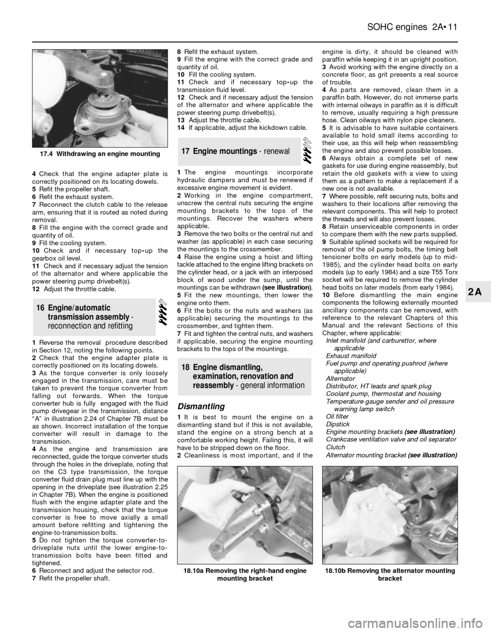
4Raise the engine using a hoist and lifting
tackle attached to the engine lifting brackets on
the cylinder head, or a jack with an interposed
block of wood under the sump, until the
mountings can be withdrawn (see illustration).
5Fit the new mountings, then lower the
engine onto them.
6Fit the bolts or the nuts and washers (as
applicable) securing the mountings to the
crossmember, and tighten them.
7Fit and tighten the central nuts, and washers
if applicable, securing the engine mounting
brackets to the tops of the mountings.
Dismantling
1It is best to mount the engine on a
dismantling stand but if this is not available,
stand the engine on a strong bench at a
comfortable working height. Failing this, it will
have to be stripped down on the floor.
2Cleanliness is most important, and if theengine is dirty, it should be cleaned with
paraffin while keeping it in an upright position.
3Avoid working with the engine directly on a
concrete floor, as grit presents a real source
of trouble.
4As parts are removed, clean them in a
paraffin bath. However, do not immerse parts
with internal oilways in paraffin as it is difficult
to remove, usually requiring a high pressure
hose. Clean oilways with nylon pipe cleaners.
5It is advisable to have suitable containers
available to hold small items according to
their use, as this will help when reassembling
the engine and also prevent possible losses.
6Always obtain a complete set of new
gaskets for use during engine reassembly, but
retain the old gaskets with a view to using
them as a pattern to make a replacement if a
new one is not available.
7Where possible, refit securing nuts, bolts and
washers to their locations after removing the
relevant components. This will help to protect
the threads and will also prevent losses.
8Retain unserviceable components in order
to compare them with the new parts supplied.
9Suitable splined sockets will be required for
removal of the oil pump bolts, the timing belt
tensioner bolts on early models (up to mid-
1985), and the cylinder head bolts on early
models (up to early 1984) and a size T55 Torx
socket will be required to remove the cylinder
head bolts on later models (from early 1984).
10Before dismantling the main engine
components the following externally mounted
ancillary components can be removed, with
reference to the relevant Chapters of this
Manual and the relevant Sections of this
Chapter, where applicable:
Inlet manifold (and carburettor, where
applicable
Exhaust manifold
Fuel pump and operating pushrod (where
applicable)
Alternator
Distributor, HT leads and spark plug
Coolant pump, thermostat and housing
Temperature gauge sender and oil pressure
warning lamp switch
Oil filter
Dipstick
Engine mounting brackets (see illustration)
Crankcase ventilation valve and oil separator
Clutch
Alternator mounting bracket (see illustration)
18Engine dismantling,
examination, renovation and
reassembly - general information
17Engine mountings - renewal
16Engine/automatic
transmission assembly -
reconnection and refitting
SOHC engines 2A¥11
2A
18.10b Removing the alternator mounting
bracket18.10a Removing the right-hand engine
mounting bracket
17.4 Withdrawing an engine mounting