jack points FORD SIERRA 1992 2.G Suspension And Steering User Guide
[x] Cancel search | Manufacturer: FORD, Model Year: 1992, Model line: SIERRA, Model: FORD SIERRA 1992 2.GPages: 20, PDF Size: 0.94 MB
Page 18 of 20

Refitting
3When refitting the fluid hoses, use new
O-rings, and take care not to overtighten the
unions. Note that with the unions fully
tightened it is still possible to rotate and move
the hoses.
4On completion of refitting, bleed the power
steering fluid circuit (Section 34).
Note: New power steering fluid hose O-rings
will be required when refitting.
All engines except 1.8 litre (R6A)
CVH and 2.0 litre DOHC
1Place a suitable container under the power
steering pump, unscrew the fluid hose unions,
and drain the fluid. Ensure that fluid is not
allowed to spill onto the alternator.
2Remove the drivebelts and unbolt the
power steering pump pulley if necessary to
ease removal.
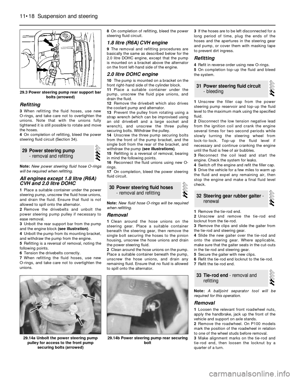
3Unbolt the rear support bar from the pump
and the engine block (see illustration).
4Unbolt the pump from its mounting bracket,
and withdraw the pump from the engine.
5Refitting is a reversal of removal, noting the
following points.
6Tension the drivebelts correctly.
7When refitting the fluid hoses, use new
O-rings, and take care not to overtighten the
unions. 8On completion of refitting, bleed the power
steering fluid circuit.
1.8 litre (R6A) CVH engine
9The removal and refitting procedures are
basically the same as described below for the
2.0 litre DOHC engine, except that the pump
is mounted on a bracket above the alternator
on the front left-hand side of the engine.
2.0 litre DOHC engine
10The pump is mounted on a bracket on the
front right-hand side of the cylinder block.
11Place a suitable container under the
pump, unscrew the fluid pipe unions, and
drain the fluid.
12Remove the drivebelt which also drives
the coolant pump and alternator.
13Prevent the pulley from rotating using a
strap wrench (which can be improvised using
an old drivebelt and a large socket and
wrench), and unscrew the three pulley
securing bolts. Withdraw the pulley.
14Unscrew the three pump securing bolts
from the front of the pump bracket, and the
single bolt from the rear of the bracket, and
withdraw the pump (see illustrations).
15Refitting is a reversal of removal, bearing
in mind the following points.
16Reconnect the fluid unions using new O-
rings.
17On completion, bleed the power steering
fluid circuit.
Note: New fluid hose O-rings will be required
when refitting.
Removal
1Clean around the hose unions on the
steering gear. Place a suitable container
beneath the steering gear, then remove the
single bolt securing the hoses to the pinion
housing, unscrew the hose unions and drain
the power steering fluid.
2Clean around the hose unions on the pump.
Place a suitable container beneath the pump,
unscrew the hose unions, and drain any
remaining fluid. Ensure that no fluid is allowed
to spill onto the alternator.3If the hoses are to be left disconnected for a
long period of time, plug the ends of the
hoses and the apertures in the steering gear
and pump, or cover them with masking tape
to prevent dirt ingress.
Refitting
4Refit in reverse order using new O-rings.
5On completion top-up the fluid and bleed
the system.
1Unscrew the filler cap from the power
steering pump reservoir and top-up the fluid
level to the maximum mark using the specified
fluid.
2Disconnect the low tension negative lead
from the ignition coil and crank the engine
several times for two second periods while
slowly turning the steering wheel from
lock-to-lock. Top-up the fluid level if
necessary and continue cranking the engine
until the fluid is free of air bubbles.
3Reconnect the coil lead and start the
engine. Check the system for leaks.
4Switch off the engine and refit the filler cap.
5Drive the vehicle for a few miles to warm up
the fluid and expel any remaining air, then
stop the engine and make a final fluid level
check.
1Remove the tie-rod end.
2Unscrew and remove the tie-rod end
locknut from the tie-rod.
3Remove the clips and slide the gaiter from
the tie-rod and steering gear.
4Slide the new gaiter over the tie-rod and
onto the steering gear. Where applicable,
make sure that the gaiter seats in the cut-outs
in the tie-rod and steering gear.
5Secure the gaiter with new clips.
6Refit the tie-rod end locknut to the tie-rod.
7Refit the tie-rod end.
Note: A balljoint separator tool will be
required for this operation.
Removal
1Loosen the relevant front roadwheel nuts,
apply the handbrake, jack up the front of the
vehicle and support on axle stands.
2Remove the roadwheel. On P100 models
mark the position of the roadwheel in relation
to one of the wheel studs before removal.
3Make alignment marks on the tie-rod and
tie-rod end, then loosen the locknut by a
quarter of a turn.
33Tie-rod end - removal and
refitting
32Steering gear rubber gaiter -
renewal
31Power steering fluid circuit
- bleeding
30Power steering fluid hoses
- removal and refitting
29Power steering pump
- removal and refitting
11•18Suspension and steering
29.3 Power steering pump rear support bar
bolts (arrowed)
29.14b Power steering pump rear securing
bolt29.14a Unbolt the power steering pump
pulley for access to the front pump
securing bolts (arrowed)
Page 19 of 20

4Extract the split pin and unscrew the
castellated nut (see illustration).
5Using a balljoint separator tool, release the
tie-rod end from the hub carrier (see
illustration).
6Unscrew the tie-rod end from the tie-rod,
noting the number of turns necessary to
remove it.
Refitting
7Refitting is a reversal of removal, bearing in
mind the following points.
8Screw the tie-rod end onto the tie-rod the
number of turns noted during removal.
9Tighten the nuts to the specified torque,
and fit a new split pin to the castellated nut.
10On P100 models, align the previously
made marks on the roadwheel and wheel
stud.
11On completion, check and if necessary
adjust the front wheel alignment.
1Front wheel alignment is defined by
camber, castor steering axis inclination and
toe setting. The first three factors are
determined in production; only toe can be
adjusted in service. Incorrect toe will cause
rapid tyre wear.
2Toe is defined as the amount by which the
distance between the front wheels, measured
at hub height, differs from the front edges tothe rear edges. If the distance between the
front edges is less than that at the rear, the
wheels are said to toe-in; the opposite case is
known as toe-out.
3To measure toe, it will be necessary to
obtain or make a tracking gauge. These are
available in motor accessory shops, or one
can be made from a length of rigid pipe or bar
with some kind of threaded adjustment facility
at one end. Many tyre specialists will also
check toe free, or for a nominal sum.
4Before measuring toe, check that all
steering and suspension components are
undamaged and that tyre pressures are
correct. The vehicle must be at approximately
kerb weight, with the spare wheel and jack in
their normal positions and any abnormal loads
removed.
5Park the vehicle on level ground and
bounce it a few times to settle the suspension.
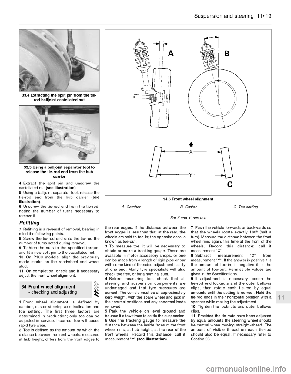
6Use the tracking gauge to measure the
distance between the inside faces of the front
wheel rims, at hub height, at the rear of the
front wheels. Record this distance; call it
measurement “Y” (see illustration).7Push the vehicle forwards or backwards so
that the wheels rotate exactly 180º (half a
turn). Measure the distance between the front
wheel rims again, this time at the front of the
wheels. Record this distance; call it
measurement “X”.
8Subtract measurement “X” from
measurement “Y”. If the answer is positive it is
the amount of toe-in; if negative it is the
amount of toe-out. Permissible values are
given in the Specifications.
9If adjustment is necessary loosen the
tie-rod end locknuts and the outer bellows
clips, then rotate each tie-rod by equal
amounts until the setting is correct. Hold the
tie-rod ends in their horizontal position with a
spanner while making the adjustment.
10Tighten the locknuts and outer bellows
clips.
11Provided the tie-rods have been adjusted
by equal amounts the steering wheel should
be central when moving straight-ahead. The
amount of visible thread on each tie-rod
should also be equal. If necessary refer to
Section 23.
34Front wheel alignment
- checking and adjusting
Suspension and steering 11•19
11
34.6 Front wheel alignment
A CamberB CastorC Toe setting
For X and Y, see text
33.5 Using a balljoint separator tool to
release the tie-rod end from the hub
carrier
33.4 Extracting the split pin from the tie-
rod balljoint castellated nut