FORD SUPER DUTY 2001 1.G Owner's Manual
Manufacturer: FORD, Model Year: 2001, Model line: SUPER DUTY, Model: FORD SUPER DUTY 2001 1.GPages: 288, PDF Size: 1.86 MB
Page 21 of 288
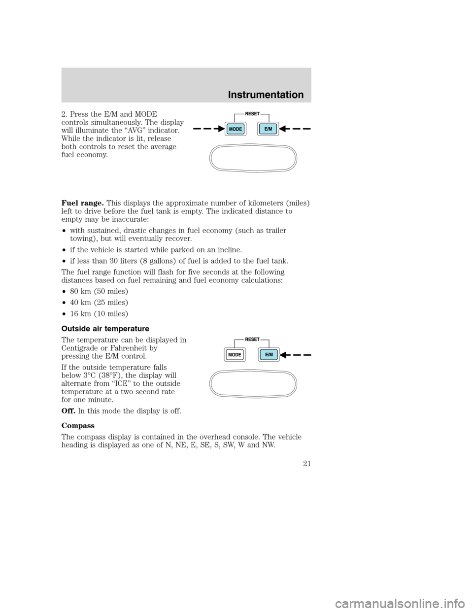
2. Press the E/M and MODE
controls simultaneously. The display
will illuminate the “AVG” indicator.
While the indicator is lit, release
both controls to reset the average
fuel economy.
Fuel range.This displays the approximate number of kilometers (miles)
left to drive before the fuel tank is empty. The indicated distance to
empty may be inaccurate:
•with sustained, drastic changes in fuel economy (such as trailer
towing), but will eventually recover.
•if the vehicle is started while parked on an incline.
•if less than 30 liters (8 gallons) of fuel is added to the fuel tank.
The fuel range function will flash for five seconds at the following
distances based on fuel remaining and fuel economy calculations:
•80 km (50 miles)
•40 km (25 miles)
•16 km (10 miles)
Outside air temperature
The temperature can be displayed in
Centigrade or Fahrenheit by
pressing the E/M control.
If the outside temperature falls
below 3°C (38°F), the display will
alternate from “ICE” to the outside
temperature at a two second rate
for one minute.
Off.In this mode the display is off.
Compass
The compass display is contained in the overhead console. The vehicle
heading is displayed as one of N, NE, E, SE, S, SW, W and NW.
Instrumentation
21
Page 22 of 288
The compass heading is displayed in average fuel economy modes, fuel
range modes and temperature modes.
The compass reading may be affected when you drive near large
buildings, bridges, power lines and powerful broadcast antenna. Magnetic
or metallic objects placed in or on the vehicle may also affect compass
accuracy. Adjustments may need to be made to the zone and calibration
of the compass.
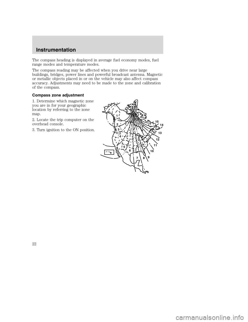
Compass zone adjustment
1. Determine which magnetic zone
you are in for your geographic
location by referring to the zone
map.
2. Locate the trip computer on the
overhead console.
3. Turn ignition to the ON position.
1
2
3
4
5
6
7891011121314 15
Instrumentation
22
Page 23 of 288
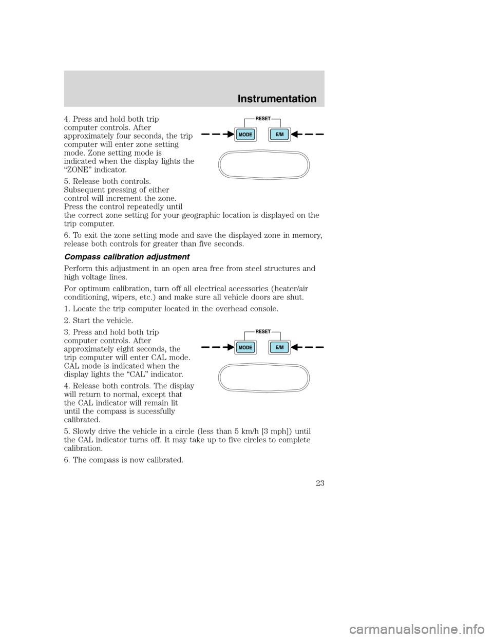
4. Press and hold both trip
computer controls. After
approximately four seconds, the trip
computer will enter zone setting
mode. Zone setting mode is
indicated when the display lights the
“ZONE” indicator.
5. Release both controls.
Subsequent pressing of either
control will increment the zone.
Press the control repeatedly until
the correct zone setting for your geographic location is displayed on the
trip computer.
6. To exit the zone setting mode and save the displayed zone in memory,
release both controls for greater than five seconds.
Compass calibration adjustment
Perform this adjustment in an open area free from steel structures and
high voltage lines.
For optimum calibration, turn off all electrical accessories (heater/air
conditioning, wipers, etc.) and make sure all vehicle doors are shut.
1. Locate the trip computer located in the overhead console.
2. Start the vehicle.
3. Press and hold both trip
computer controls. After
approximately eight seconds, the
trip computer will enter CAL mode.
CAL mode is indicated when the
display lights the “CAL” indicator.
4. Release both controls. The display
will return to normal, except that
the CAL indicator will remain lit
until the compass is sucessfully
calibrated.
5. Slowly drive the vehicle in a circle (less than 5 km/h [3 mph]) until
the CAL indicator turns off. It may take up to five circles to complete
calibration.
6. The compass is now calibrated.
Instrumentation
23
Page 24 of 288
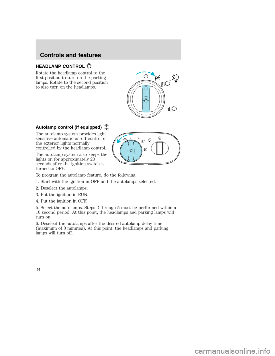
HEADLAMP CONTROL
Rotate the headlamp control to the
first position to turn on the parking
lamps. Rotate to the second position
to also turn on the headlamps.
Autolamp control (if equipped)
The autolamp system provides light
sensitive automatic on-off control of
the exterior lights normally
controlled by the headlamp control.
The autolamp system also keeps the
lights on for approximately 20
seconds after the ignition switch is
turned to OFF.
To program the autolamp feature, do the following:
1. Start with the ignition in OFF and the autolamps selected.
2. Deselect the autolamps.
3. Put the ignition in RUN.
4. Put the ignition in OFF.
5. Select the autolamps. Steps 2 through 5 must be performed within a
10 second period. At this point, the headlamps and parking lamps will
turn on.
6. Deselect the autolamps after the desired autolamp delay time
(maximum of 3 minutes). At this point, the headlamps and parking
lamps will turn off.
A
Controls and features
24
Page 25 of 288
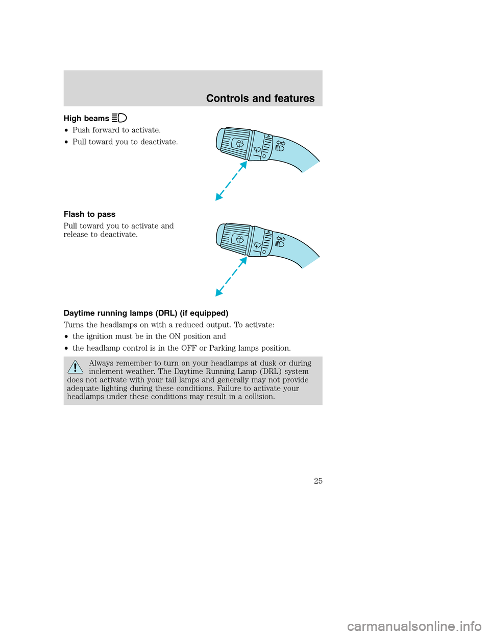
High beams
•Push forward to activate.
•Pull toward you to deactivate.
Flash to pass
Pull toward you to activate and
release to deactivate.
Daytime running lamps (DRL) (if equipped)
Turns the headlamps on with a reduced output. To activate:
•the ignition must be in the ON position and
•the headlamp control is in the OFF or Parking lamps position.
Always remember to turn on your headlamps at dusk or during
inclement weather. The Daytime Running Lamp (DRL) system
does not activate with your tail lamps and generally may not provide
adequate lighting during these conditions. Failure to activate your
headlamps under these conditions may result in a collision.
Controls and features
25
Page 26 of 288
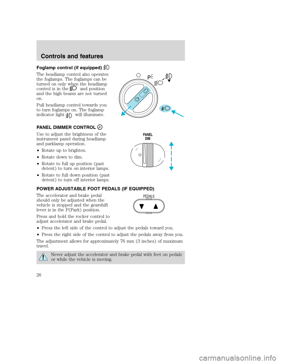
Foglamp control (if equipped)
The headlamp control also operates
the foglamps. The foglamps can be
turned on only when the headlamp
control is in the
and position
and the high beams are not turned
on.
Pull headlamp control towards you
to turn foglamps on. The foglamp
indicator light
will illuminate.
PANEL DIMMER CONTROL
Use to adjust the brightness of the
instrument panel during headlamp
and parklamp operation.
•Rotate up to brighten.
•Rotate down to dim.
•Rotate to full up position (past
detent) to turn on interior lamps.
•Rotate to full down position (past
detent) to turn off interior lamps.
POWER ADJUSTABLE FOOT PEDALS (IF EQUIPPED)
The accelerator and brake pedal
should only be adjusted when the
vehicle is stopped and the gearshift
lever is in the P(Park) position.
Press and hold the rocker control to
adjust accelerator and brake pedal.
•Press the left side of the control to adjust the pedals toward you.
•Press the right side of the control to adjust the pedals away from you.
The adjustment allows for approximately 76 mm (3 inches) of maximum
travel.
Never adjust the accelerator and brake pedal with feet on pedals
or while the vehicle is moving.
PANEL
DIM
PEDALS
Controls and features
26
Page 27 of 288
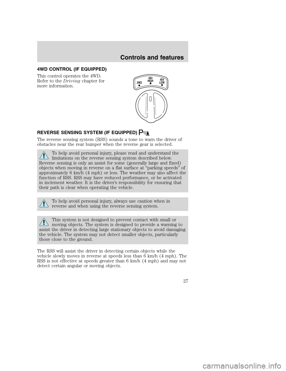
4WD CONTROL (IF EQUIPPED)
This control operates the 4WD.
Refer to theDrivingchapter for
more information.
REVERSE SENSING SYSTEM (IF EQUIPPED)
The reverse sensing system (RSS) sounds a tone to warn the driver of
obstacles near the rear bumper when the reverse gear is selected.
To help avoid personal injury, please read and understand the
limitations on the reverse sensing system described below.
Reverse sensing is only an assist for some (generally large and fixed)
objects when moving in reverse on a flat surface at “parking speeds” of
approximately 6 km/h (4 mph) or less. The weather may also affect the
function of RSS. RSS may have reduced performance, or be activated
in inclement weather. It is the driver’s responsibility for ensuring that
their path is clear when operating the vehicle.
To help avoid personal injury, always use caution when in
reverse and when using the reverse sensing system.
This system is not designed to prevent contact with small or
moving objects. The system is designed to provide a warning to
assist the driver in detecting large stationary objects to avoid damaging
the vehicle. The system may not detect smaller objects, particularly
those close to the ground.
The RSS will assist the driver in detecting certain objects while the
vehicle slowly moves in reverse at speeds less than 6 km/h (4 mph). The
RSS is not effective at speeds greater than 6 km/h (4 mph) and may not
detect certain angular or moving objects.
4X4
HIGH
2WD4X4
LOW
Controls and features
27
Page 28 of 288
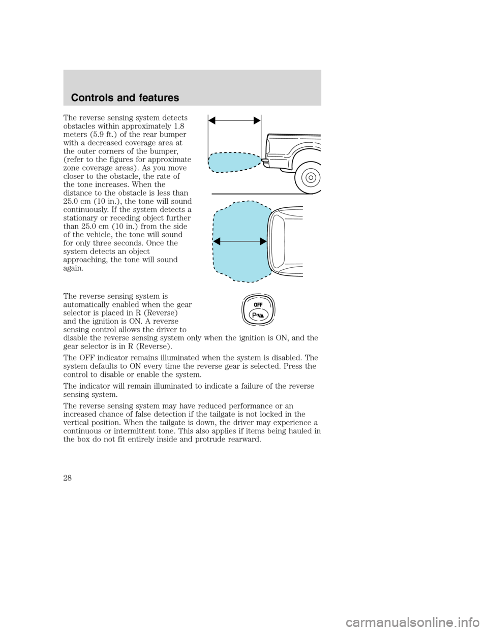
The reverse sensing system detects
obstacles within approximately 1.8
meters (5.9 ft.) of the rear bumper
with a decreased coverage area at
the outer corners of the bumper,
(refer to the figures for approximate
zone coverage areas). As you move
closer to the obstacle, the rate of
the tone increases. When the
distance to the obstacle is less than
25.0 cm (10 in.), the tone will sound
continuously. If the system detects a
stationary or receding object further
than 25.0 cm (10 in.) from the side
of the vehicle, the tone will sound
for only three seconds. Once the
system detects an object
approaching, the tone will sound
again.
The reverse sensing system is
automatically enabled when the gear
selector is placed in R (Reverse)
and the ignition is ON. A reverse
sensing control allows the driver to
disable the reverse sensing system only when the ignition is ON, and the
gear selector is in R (Reverse).
The OFF indicator remains illuminated when the system is disabled. The
system defaults to ON every time the reverse gear is selected. Press the
control to disable or enable the system.
The indicator will remain illuminated to indicate a failure of the reverse
sensing system.
The reverse sensing system may have reduced performance or an
increased chance of false detection if the tailgate is not locked in the
vertical position. When the tailgate is down, the driver may experience a
continuous or intermittent tone. This also applies if items being hauled in
the box do not fit entirely inside and protrude rearward.
OFF
Controls and features
28
Page 29 of 288
Always keep the sensors (located on the rear bumper/fascia) free
from dirt, snow and ice (do not clean the sensors with sharp
objects). These elements may cause the system to operate
inaccurately.
If the vehicle sustains damage to the rear bumper/fascia, leaving
it misaligned or bent, the sensing zone may be altered causing
inaccurate measurement of obstacles or false alarms.
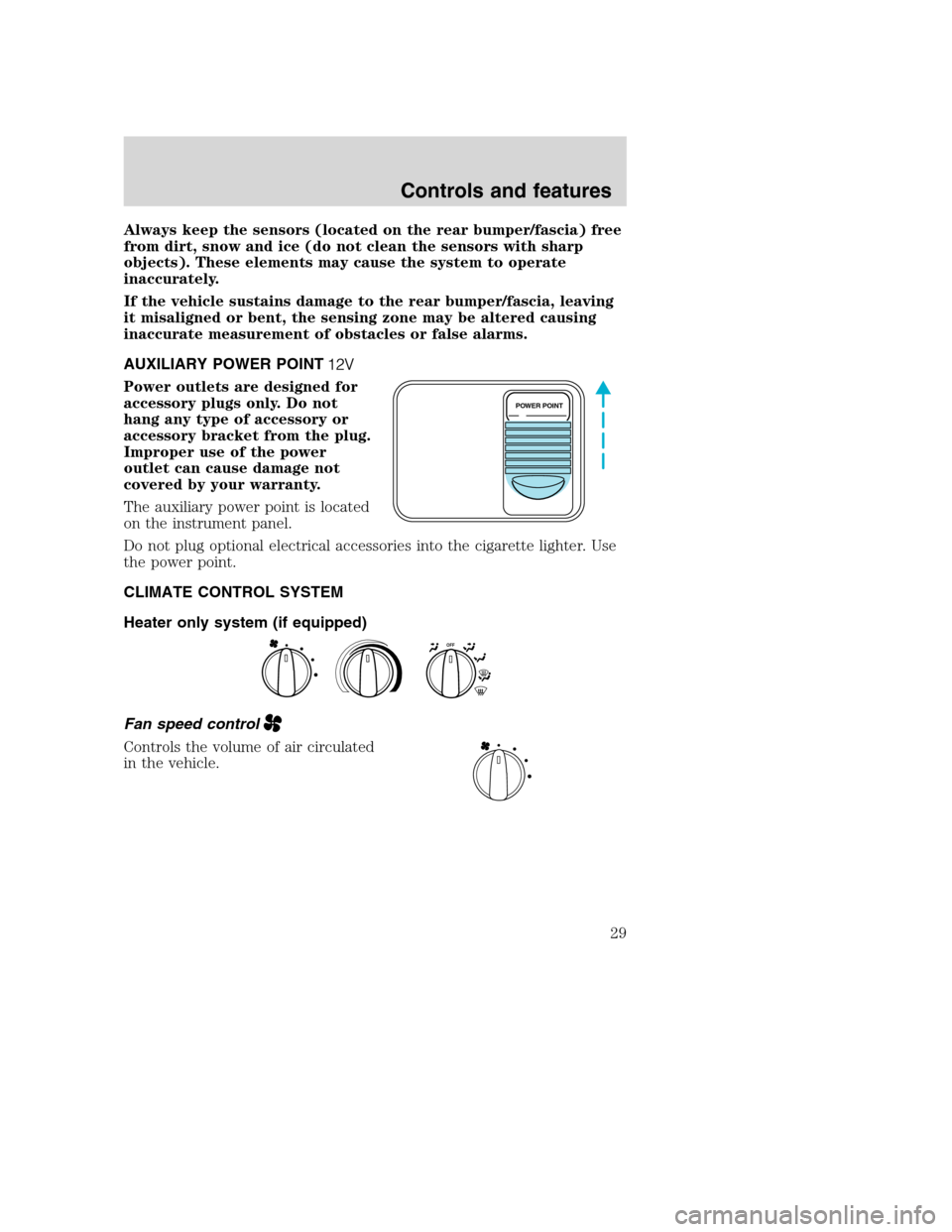
AUXILIARY POWER POINT
Power outlets are designed for
accessory plugs only. Do not
hang any type of accessory or
accessory bracket from the plug.
Improper use of the power
outlet can cause damage not
covered by your warranty.
The auxiliary power point is located
on the instrument panel.
Do not plug optional electrical accessories into the cigarette lighter. Use
the power point.
CLIMATE CONTROL SYSTEM
Heater only system (if equipped)
Fan speed control
Controls the volume of air circulated
in the vehicle.
POWER POINT
O
F
F
Controls and features
29
Page 30 of 288
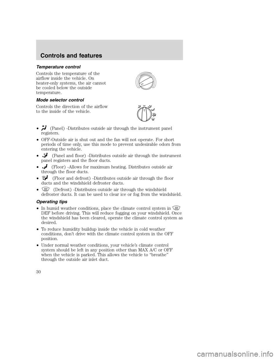
Temperature control
Controls the temperature of the
airflow inside the vehicle. On
heater-only systems, the air cannot
be cooled below the outside
temperature.
Mode selector control
Controls the direction of the airflow
to the inside of the vehicle.
•
(Panel) -Distributes outside air through the instrument panel
registers.
•OFF-Outside air is shut out and the fan will not operate. For short
periods of time only, use this mode to prevent undesirable odors from
entering the vehicle.
•
(Panel and floor) -Distributes outside air through the instrument
panel registers and the floor ducts.
•
(Floor) -Allows for maximum heating. Distributes outside air
through the floor ducts.
•
(Floor and defrost) -Distributes outside air through the floor
ducts and the windshield defroster ducts.
•
(Defrost) -Distributes outside air through the windshield
defroster ducts. It can be used to clear ice or fog from the windshield.
Operating tips
•In humid weather conditions, place the climate control system in
DEF before driving. This will reduce fogging on your windshield. Once
the windshield has been cleared, operate the climate control system as
desired.
•To reduce humidity buildup inside the vehicle in cold weather
conditions, don’t drive with the climate control system in the OFF
position.
•Under normal weather conditions, your vehicle’s climate control
system should be left in any position other than MAX A/C or OFF
when the vehicle is parked. This allows the vehicle to “breathe”
through the outside air inlet duct.
O
F
F
Controls and features
30