maintenance FORD SUPER DUTY 2004 1.G Owners Manual
[x] Cancel search | Manufacturer: FORD, Model Year: 2004, Model line: SUPER DUTY, Model: FORD SUPER DUTY 2004 1.GPages: 304, PDF Size: 3.96 MB
Page 3 of 304
Maintenance and Specifications 232
Engine compartment 234
Engine oil 235
Battery 238
Fuel information 246
Air filter(s) 263
Part numbers 277
Refill capacities 278
Lubricant specifications 281
Accessories 296
Index 299
All rights reserved. Reproduction by any means, electronic or mechanical
including photocopying, recording or by any information storage and retrieval
system or translation in whole or part is not permitted without written
authorization from Ford Motor Company. Ford may change the contents without
notice and without incurring obligation.
Copyright © 2003 Ford Motor Company
2004 F250/350/450/550(f23)
Owners Guide (post-2002-fmt)
USA English(fus)
Table of Contents
3
Page 5 of 304
SAFETY AND ENVIRONMENT PROTECTION
Warning symbols in this guide
How can you reduce the risk of personal injury and prevent possible
damage to others, your vehicle and its equipment? In this guide, answers
to such questions are contained in comments highlighted by the warning
triangle symbol. These comments should be read and observed.
Warning symbols on your vehicle
When you see this symbol, it is
imperative that you consult the
relevant section of this guide before
touching or attempting adjustment
of any kind.
Protecting the environment
We must all play our part in
protecting the environment. Correct
vehicle usage and the authorized
disposal of waste cleaning and
lubrication materials are significant
steps towards this aim. Information in this respect is highlighted in this
guide with the tree symbol.
BREAKING-IN YOUR VEHICLE
Your vehicle does not need an extensive break-in. Try not to drive
continuously at the same speed for the first 1,600 km (1,000 miles) of
new vehicle operation. Vary your speed to allow parts to adjust
themselves to other parts.
Drive your new vehicle for at least 800 km (500 miles) before towing a
trailer or snowplowing.
Do not add friction modifier compounds or special break-in oils during
the first few thousand kilometers (miles) of operation, since these
additives may prevent piston ring seating. SeeEngine oilin the
Maintenance and specificationschapter for more information on oil
usage.
2004 F250/350/450/550(f23)
Owners Guide (post-2002-fmt)
USA English(fus)
Introduction
5
Page 7 of 304
Special instructions
For your added safety, your vehicle is fitted with sophisticated electronic
controls.
Please read the sectionSupplemental Restraint System (SRS)
in theSeating and safety restraintschapter. Failure to follow
the specific warnings and instructions could result in personal injury.
Front seat mounted rear facing child or infant seats should
NEVERbe used in front of a passenger side air bag unless the
air bag can be and is turned OFF.
Notice to owners of diesel-powered vehicles
Read the 6.0 Liter Power Stroke Direct Injection Turbo Diesel Owner’s
Guide Supplement for information regarding correct operation and
maintenance of your Diesel-powered light truck.
Notice to owners of pickup trucks and utility type vehicles
Utility vehicles have a significantly higher rollover rate than
other types of vehicles.
Before you drive your vehicle, please read this Owner’s Guide carefully.
Your vehicle is not a passenger car. As with other vehicles of this type,
failure to operate this vehicle correctly may result in loss of vehicle
control, vehicle rollover, personal injury or death.
Be sure to readDriving off roadin theDrivingchapter.
2004 F250/350/450/550(f23)
Owners Guide (post-2002-fmt)
USA English(fus)
Introduction
7
Page 12 of 304
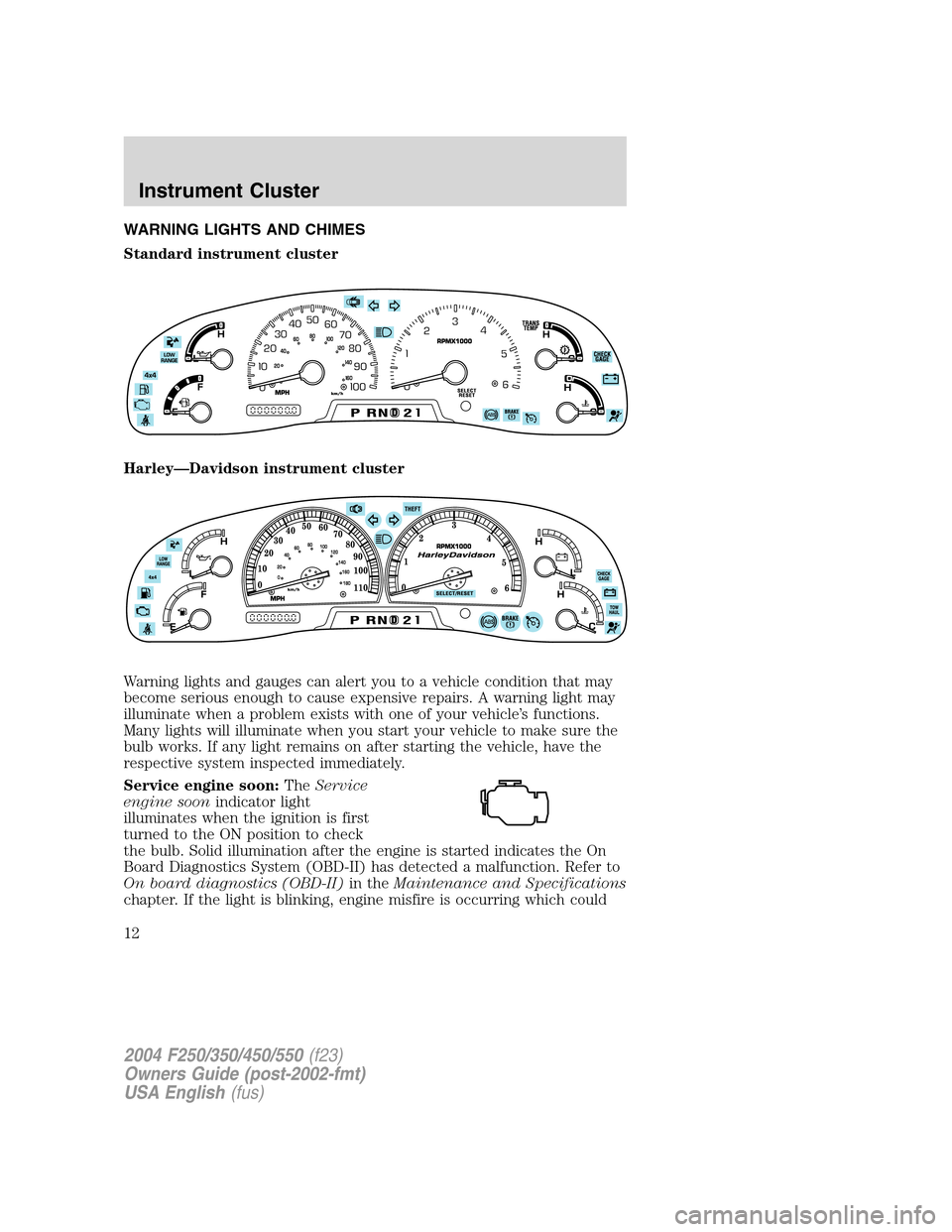
WARNING LIGHTS AND CHIMES
Standard instrument cluster
Harley—Davidson instrument cluster
Warning lights and gauges can alert you to a vehicle condition that may
become serious enough to cause expensive repairs. A warning light may
illuminate when a problem exists with one of your vehicle’s functions.
Many lights will illuminate when you start your vehicle to make sure the
bulb works. If any light remains on after starting the vehicle, have the
respective system inspected immediately.
Service engine soon:TheService
engine soonindicator light
illuminates when the ignition is first
turned to the ON position to check
the bulb. Solid illumination after the engine is started indicates the On
Board Diagnostics System (OBD-II) has detected a malfunction. Refer to
On board diagnostics (OBD-II)in theMaintenance and Specifications
chapter. If the light is blinking, engine misfire is occurring which could
2004 F250/350/450/550(f23)
Owners Guide (post-2002-fmt)
USA English(fus)
Instrument Cluster
Instrument Cluster
12
Page 13 of 304
damage your catalytic converter. Drive in a moderate fashion (avoid
heavy acceleration and deceleration) and have your vehicle serviced
immediately.
Under engine misfire conditions, excessive exhaust temperatures
could damage the catalytic converter, the fuel system, interior
floor coverings or other vehicle components, possibly causing a fire.
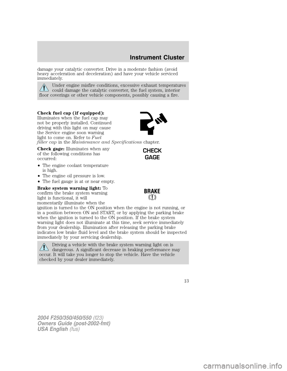
Check fuel cap (if equipped):
Illuminates when the fuel cap may
not be properly installed. Continued
driving with this light on may cause
the Service engine soon warning
light to come on. Refer toFuel
filler capin theMaintenance and Specificationschapter.
Check gage:Illuminates when any
of the following conditions has
occurred:
•The engine coolant temperature
is high.
•The engine oil pressure is low.
•The fuel gauge is at or near empty.
Brake system warning light:To
confirm the brake system warning
light is functional, it will
momentarily illuminate when the
ignition is turned to the ON position when the engine is not running, or
in a position between ON and START, or by applying the parking brake
when the ignition is turned to the ON position. If the brake system
warning light does not illuminate at this time, seek service immediately
from your dealership. Illumination after releasing the parking brake
indicates low brake fluid level and the brake system should be inspected
immediately by your servicing dealership.
Driving a vehicle with the brake system warning light on is
dangerous. A significant decrease in braking performance may
occur. It will take you longer to stop the vehicle. Have the vehicle
checked by your dealer immediately.
CHECK
GAGE
2004 F250/350/450/550(f23)
Owners Guide (post-2002-fmt)
USA English(fus)
Instrument Cluster
13
Page 17 of 304
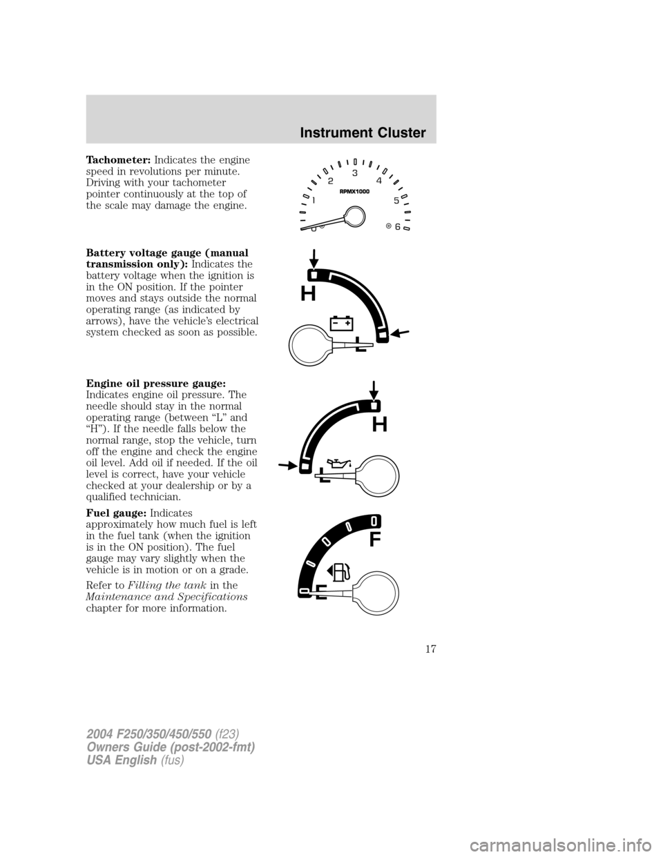
Tachometer:Indicates the engine
speed in revolutions per minute.
Driving with your tachometer
pointer continuously at the top of
the scale may damage the engine.
Battery voltage gauge (manual
transmission only):Indicates the
battery voltage when the ignition is
in the ON position. If the pointer
moves and stays outside the normal
operating range (as indicated by
arrows), have the vehicle’s electrical
system checked as soon as possible.
Engine oil pressure gauge:
Indicates engine oil pressure. The
needle should stay in the normal
operating range (between“L”and
“H”). If the needle falls below the
normal range, stop the vehicle, turn
off the engine and check the engine
oil level. Add oil if needed. If the oil
level is correct, have your vehicle
checked at your dealership or by a
qualified technician.
Fuel gauge:Indicates
approximately how much fuel is left
in the fuel tank (when the ignition
is in the ON position). The fuel
gauge may vary slightly when the
vehicle is in motion or on a grade.
Refer toFilling the tankin the
Maintenance and Specifications
chapter for more information.
2004 F250/350/450/550(f23)
Owners Guide (post-2002-fmt)
USA English(fus)
Instrument Cluster
17
Page 18 of 304
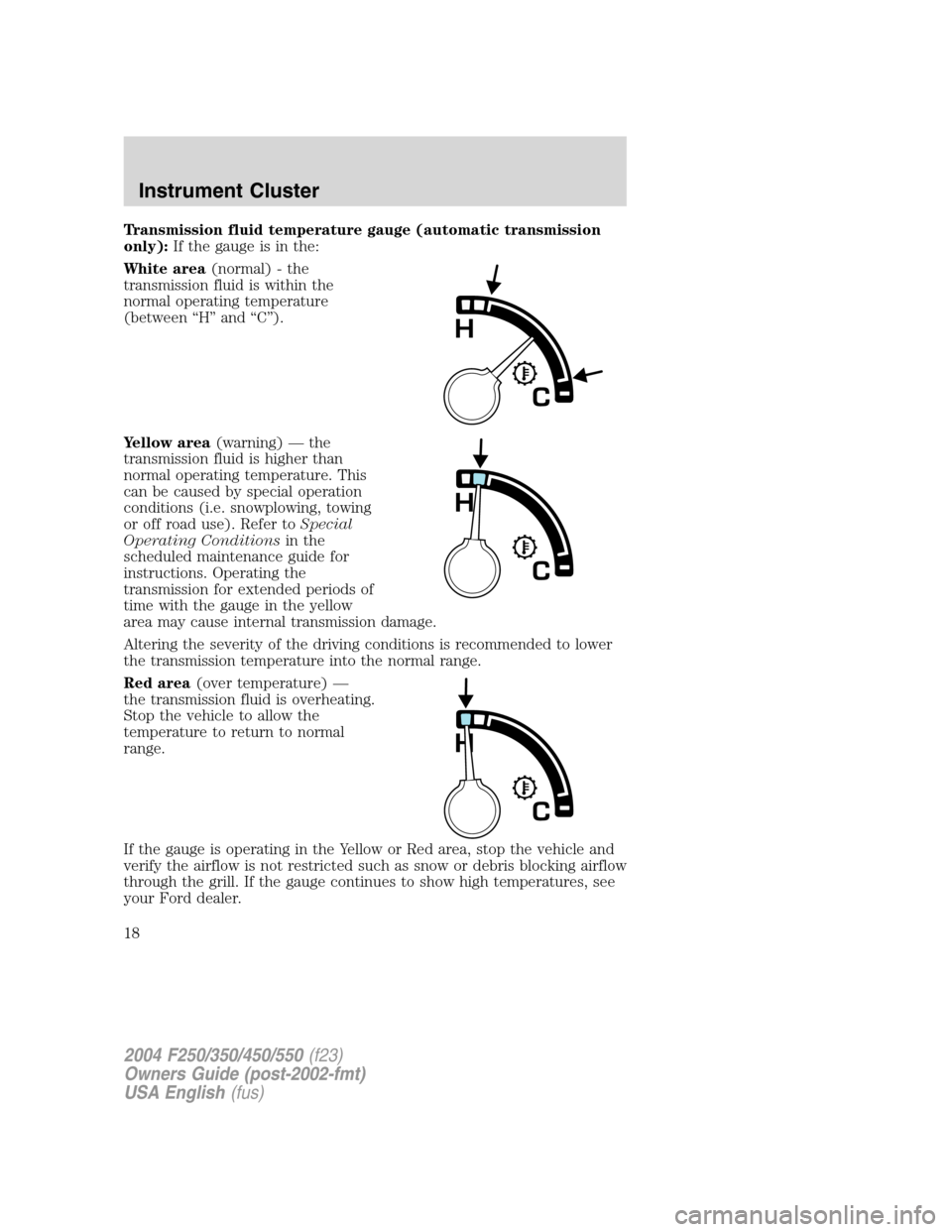
Transmission fluid temperature gauge (automatic transmission
only):If the gauge is in the:
White area(normal) - the
transmission fluid is within the
normal operating temperature
(between“H”and“C”).
Yellow area(warning)—the
transmission fluid is higher than
normal operating temperature. This
can be caused by special operation
conditions (i.e. snowplowing, towing
or off road use). Refer toSpecial
Operating Conditionsin the
scheduled maintenance guide for
instructions. Operating the
transmission for extended periods of
time with the gauge in the yellow
area may cause internal transmission damage.
Altering the severity of the driving conditions is recommended to lower
the transmission temperature into the normal range.
Red area(over temperature)—
the transmission fluid is overheating.
Stop the vehicle to allow the
temperature to return to normal
range.
If the gauge is operating in the Yellow or Red area, stop the vehicle and
verify the airflow is not restricted such as snow or debris blocking airflow
through the grill. If the gauge continues to show high temperatures, see
your Ford dealer.
2004 F250/350/450/550(f23)
Owners Guide (post-2002-fmt)
USA English(fus)
Instrument Cluster
18
Page 97 of 304
The driver and front outboard passenger safety belt system (including
retractors, buckles and height adjusters) must be replaced if the vehicle
is involved in a collision that results in the activation of the safety belt
pretensioners. Refer to theSafety belt maintenancesection in this
chapter.
Failure to replace the safety belt assembly under the above
conditions could result in severe personal injuries in the event of
a collision.
Front safety belt height adjustment
The front outboard seats are equipped with belt height adjusters.
If your vehicle is equipped with seat integrated restraints (SIR), you will
not have a safety belt height adjuster.
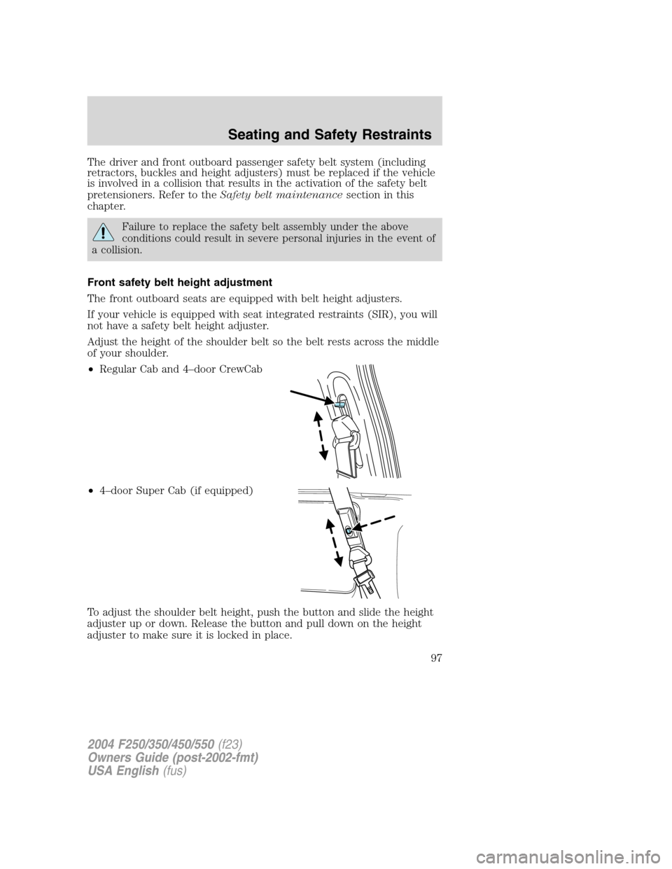
Adjust the height of the shoulder belt so the belt rests across the middle
of your shoulder.
•Regular Cab and 4–door CrewCab
•4–door Super Cab (if equipped)
To adjust the shoulder belt height, push the button and slide the height
adjuster up or down. Release the button and pull down on the height
adjuster to make sure it is locked in place.
2004 F250/350/450/550(f23)
Owners Guide (post-2002-fmt)
USA English(fus)
Seating and Safety Restraints
97
Page 103 of 304
•This will disable BeltMinder if it is currently enabled, or enable
BeltMinder if it is currently disabled.
7. Confirmation of disabling BeltMinder is provided by the safety belt
warning light flashing four times per second for three seconds.
8. Confirmation of enabling BeltMinder is provided by:
•The safety belt warning light flashing four times per second for three
seconds.
•Followed by three seconds with the safety belt warning light off.
•Once again, the safety belt warning light will flash four times per
second for three seconds.
9. After receiving confirmation, the deactivation/activation procedure is
complete.
Safety belt extension assembly
If the safety belt is too short when fully extended, there is a 20 cm (8
inch) safety belt extension assembly that can be added (part number
611C22). This assembly can be obtained from your dealer at no cost.
Use only extensions manufactured by the same supplier as the safety
belt. Manufacturer identification is located at the end of the webbing on
the label. Also, use the safety belt extension only if the safety belt is too
short for you when fully extended.
Do not use extensions to change the fit of the shoulder belt
across the torso.
Safety belt maintenance
Inspect the safety belt systems periodically to make sure they work
properly and are not damaged. Inspect the safety belts to make sure
there are no nicks, tears or cuts. Replace if necessary. All safety belt
assemblies, including retractors, buckles, front seat belt buckle
assemblies, buckle support assemblies (slide bar-if equipped), shoulder
belt height adjusters (if equipped), shoulder belt guide on seatback (if
equipped), child safety seat LATCH and tether anchors, and attaching
hardware, should be inspected after a collision. Ford Motor Company
recommends that all safety belt assemblies used in vehicles involved in a
collision be replaced. However, if the collision was minor and a qualified
technician finds that the belts do not show damage and continue to
operate properly, they do not need to be replaced. Safety belt assemblies
not in use during a collision should also be inspected and replaced if
either damage or improper operation is noted.
2004 F250/350/450/550(f23)
Owners Guide (post-2002-fmt)
USA English(fus)
Seating and Safety Restraints
103
Page 108 of 304
The diagnostic module monitors its own internal circuits and the
supplemental air bag electrical system wiring (including the impact
sensors), the system wiring, the air bag system readiness light, the air
bag back up power and the air bag ignitors.
Determining if the system is operational
The SRS uses a readiness light in the instrument cluster or a tone to
indicate the condition of the system. Refer toAir bag readinesssection
in theInstrument clusterchapter. Routine maintenance of the air bag is
not required.
A difficulty with the system is indicated by one or more of the following:
•The readiness light will either
flash or stay lit.
•The readiness light will not
illuminate immediately after
ignition is turned on.
•A series of five beeps will be heard. The tone pattern will repeat
periodically until the problem and/or light are repaired.
If any of these things happen, even intermittently, have the SRS serviced
at your dealership or by a qualified technician immediately. Unless
serviced, the system may not function properly in the event of a
collision.
Disposal of air bags and air bag equipped vehicles (including
pretensioners)
See your local dealership or qualified technician. Air bags MUST BE
disposed of by qualified personnel.
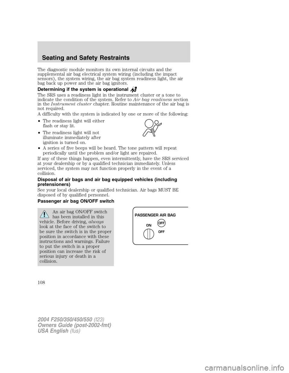
Passenger air bag ON/OFF switch
An air bag ON/OFF switch
has been installed in this
vehicle. Before driving,always
look at the face of the switch to
be sure the switch is in the proper
position in accordance with these
instructions and warnings. Failure
to put the switch in a proper
position can increase the risk of
serious injury or death in a
collision.PASSENGER AIR BAG
OFF
OFF ON
2004 F250/350/450/550(f23)
Owners Guide (post-2002-fmt)
USA English(fus)
Seating and Safety Restraints
108