brakes FORD SUPER DUTY 2005 1.G Owners Manual
[x] Cancel search | Manufacturer: FORD, Model Year: 2005, Model line: SUPER DUTY, Model: FORD SUPER DUTY 2005 1.GPages: 304, PDF Size: 6.38 MB
Page 2 of 304
Locks and Security 80
Keys 80
Locks 80
Seating and Safety Restraints 90
Seating 90
Safety restraints 97
Air bags 108
Child restraints 117
Tires, Wheels and Loading 129
Tire Information 132
Tire Inflation 133
Changing tires 137
Lug Nut Torque 148
Vehicle loading 160
Trailer towing 165
Recreational towing 174
Driving 175
Starting 175
Brakes 181
Transmission operation 184
Roadside Emergencies 211
Getting roadside assistance 211
Hazard flasher switch 212
Fuel pump shut-off switch 213
Fuses and relays 213
Jump starting 221
Wrecker towing 227
Customer Assistance 229
Reporting safety defects (U.S. only) 237
Table of Contents
2
REVIEW COPY
2005 F250/350/450/550(f23), Owners Guide (post-2002-fmt)(own2002),
Market:USA_English(fus)
Page 64 of 304
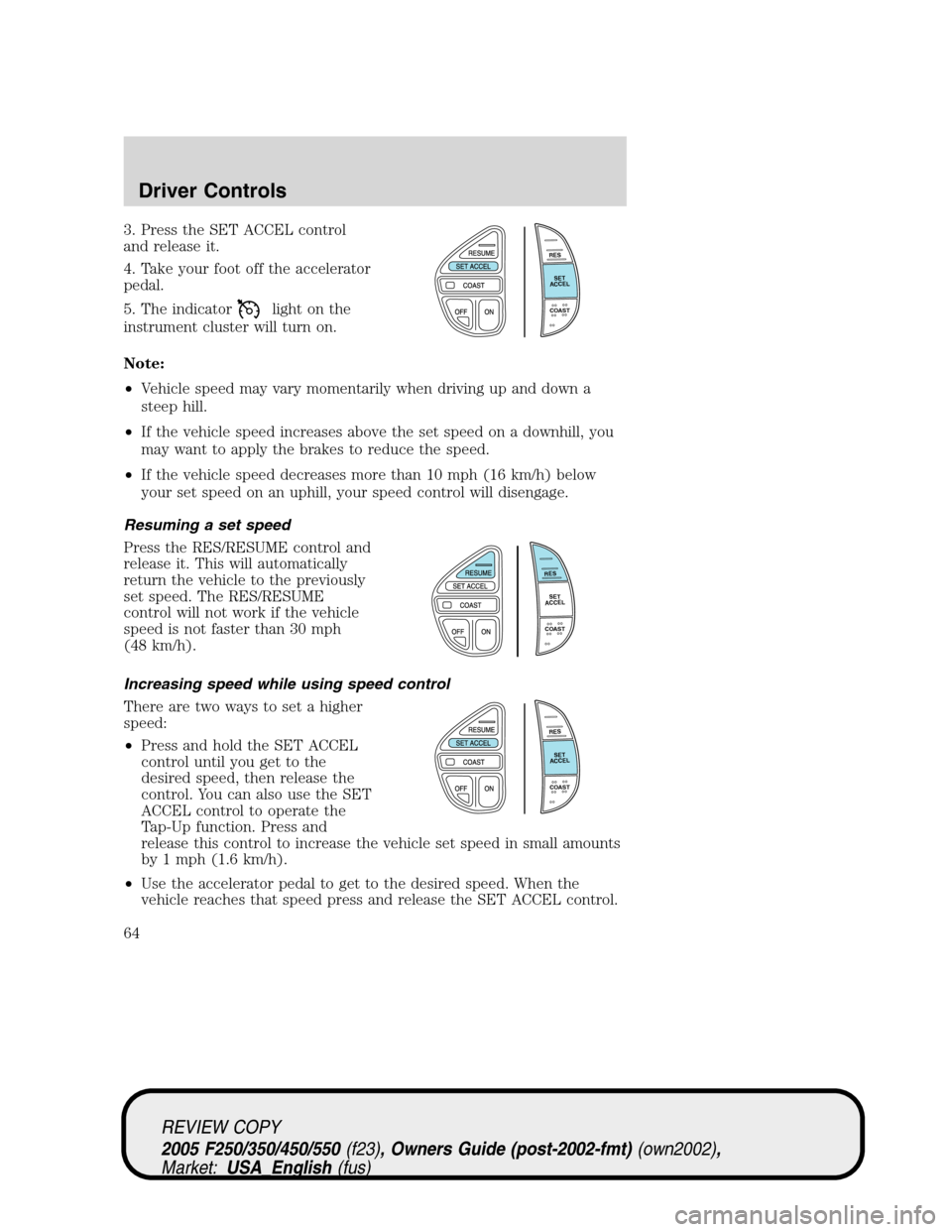
3. Press the SET ACCEL control
and release it.
4. Take your foot off the accelerator
pedal.
5. The indicator
light on the
instrument cluster will turn on.
Note:
•Vehicle speed may vary momentarily when driving up and down a
steep hill.
•If the vehicle speed increases above the set speed on a downhill, you
may want to apply the brakes to reduce the speed.
•If the vehicle speed decreases more than 10 mph (16 km/h) below
your set speed on an uphill, your speed control will disengage.
Resuming a set speed
Press the RES/RESUME control and
release it. This will automatically
return the vehicle to the previously
set speed. The RES/RESUME
control will not work if the vehicle
speed is not faster than 30 mph
(48 km/h).
Increasing speed while using speed control
There are two ways to set a higher
speed:
•Press and hold the SET ACCEL
control until you get to the
desired speed, then release the
control. You can also use the SET
ACCEL control to operate the
Tap-Up function. Press and
release this control to increase the vehicle set speed in small amounts
by 1 mph (1.6 km/h).
•Use the accelerator pedal to get to the desired speed. When the
vehicle reaches that speed press and release the SET ACCEL control.
RES
SET
ACCEL
COAST
RES
SET
ACCEL
COAST
RES
SET
ACCEL
COAST
REVIEW COPY
2005 F250/350/450/550(f23), Owners Guide (post-2002-fmt)(own2002),
Market:USA_English(fus)
Driver Controls
64
Page 68 of 304
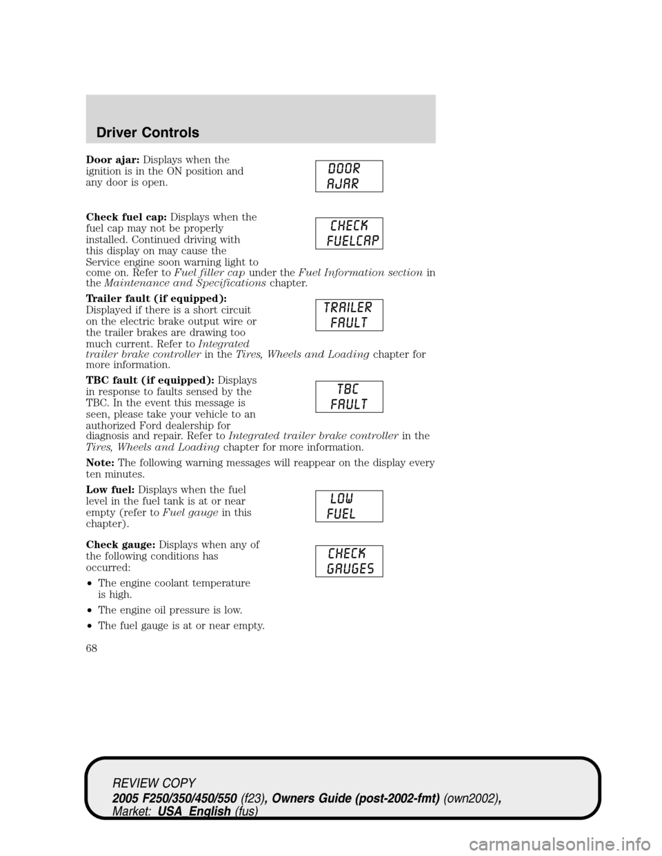
Door ajar:Displays when the
ignition is in the ON position and
any door is open.
Check fuel cap:Displays when the
fuel cap may not be properly
installed. Continued driving with
this display on may cause the
Service engine soon warning light to
come on. Refer toFuel filler capunder theFuel Information sectionin
theMaintenance and Specificationschapter.
Trailer fault (if equipped):
Displayed if there is a short circuit
on the electric brake output wire or
the trailer brakes are drawing too
much current. Refer toIntegrated
trailer brake controllerin theTires, Wheels and Loadingchapter for
more information.
TBC fault (if equipped):Displays
in response to faults sensed by the
TBC. In the event this message is
seen, please take your vehicle to an
authorized Ford dealership for
diagnosis and repair. Refer toIntegrated trailer brake controllerin the
Tires, Wheels and Loadingchapter for more information.
Note:The following warning messages will reappear on the display every
ten minutes.
Low fuel:Displays when the fuel
level in the fuel tank is at or near
empty (refer toFuel gaugein this
chapter).
Check gauge:Displays when any of
the following conditions has
occurred:
•The engine coolant temperature
is high.
•The engine oil pressure is low.
•The fuel gauge is at or near empty.
REVIEW COPY
2005 F250/350/450/550(f23), Owners Guide (post-2002-fmt)(own2002),
Market:USA_English(fus)
Driver Controls
68
Page 77 of 304
LOW OIL PRESSURE.Displayed when the engine oil pressure is low. If
this warning message is displayed, check the level of the engine oil.
Refer toEngine oilin theMaintenance and Specificationschapter for
information about adding engine oil. If the oil level is OK and this
warning persists, shut down the engine immediately and contact your
dealership for service.
CHECK FUEL CAP.Displayed when the fuel filler cap is not properly
installed. Check the fuel filler cap for proper installation. Refer toFuel
filler capunder theFuel Information sectionin theMaintenance and
Specificationschapter.
ENGINE FAILSAFE MODE.Displayed when the engine has defaulted
to a ’limp-home’ operation. If the warning stays on or continues to come
on, contact your dealer as soon as possible.
CHECK COMPASS MODULE.Displayed when the compass is not
operating properly. If the warning stays on or continues to come on,
contact your dealer as soon as possible.
TRAILER DISCONNECTED (if equipped):Displayed when a trailer
connection becomes disconnected, either intentionally or unintentionally,
and has been sensed during a given ignition cycle. Refer toIntergrated
trailer brake controllerin theTires, Wheels and Loadingchapter for
more information.
TRAILER FAULT (if equipped):Displayed if there is a short circuit on
the electric brake output wire or the trailer brakes are drawing too much
current. Refer toIntergrated trailer brake controllerin theTires,
Wheels and Loadingchapter for more information.
TBC FAULT (if equipped):Displayed in response to faults sensed by
the TBC. In the event this message is seen, please take your vehicle to
an authorized Ford dealership for diagnosis and repair. Refer to
Intergrated trailer brake controllerin theTires, Wheels and Loading
chapter for more information.
WATER IN FUEL (diesel only):Refer toInstrumentationin your6.0
Liter Power Stroke Direct Injection Turbo Diesel Owner’s Guide
Supplement.
CHECK AIR FILTER (diesel only):Refer toInstrumentationin your
6.0 Liter Power Stroke Direct Injection Turbo Diesel Owner’s Guide
Supplement.
REVIEW COPY
2005 F250/350/450/550(f23), Owners Guide (post-2002-fmt)(own2002),
Market:USA_English(fus)
Driver Controls
77
Page 99 of 304
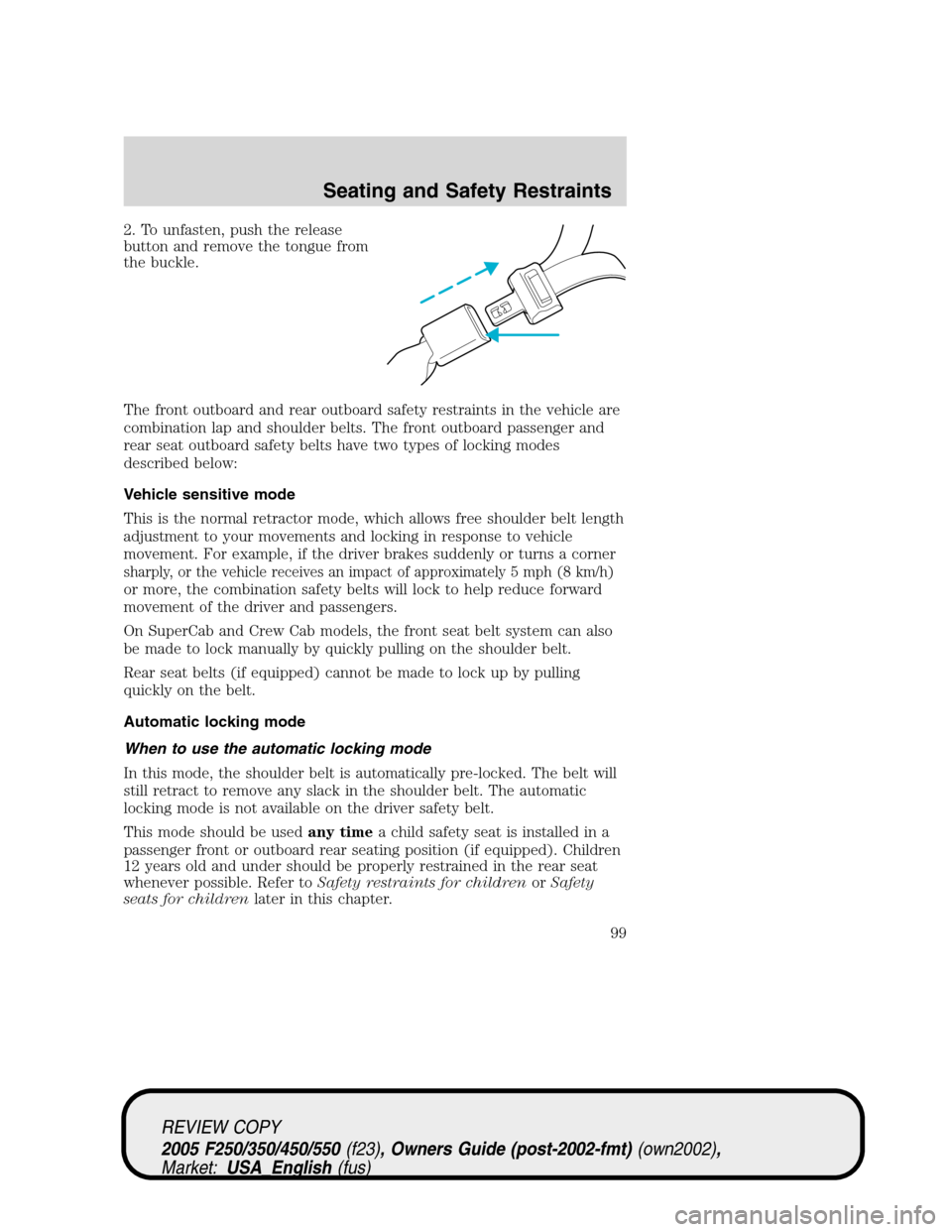
2. To unfasten, push the release
button and remove the tongue from
the buckle.
The front outboard and rear outboard safety restraints in the vehicle are
combination lap and shoulder belts. The front outboard passenger and
rear seat outboard safety belts have two types of locking modes
described below:
Vehicle sensitive mode
This is the normal retractor mode, which allows free shoulder belt length
adjustment to your movements and locking in response to vehicle
movement. For example, if the driver brakes suddenly or turns a corner
sharply, or the vehicle receives an impact of approximately 5 mph (8 km/h)
or more, the combination safety belts will lock to help reduce forward
movement of the driver and passengers.
On SuperCab and Crew Cab models, the front seat belt system can also
be made to lock manually by quickly pulling on the shoulder belt.
Rear seat belts (if equipped) cannot be made to lock up by pulling
quickly on the belt.
Automatic locking mode
When to use the automatic locking mode
In this mode, the shoulder belt is automatically pre-locked. The belt will
still retract to remove any slack in the shoulder belt. The automatic
locking mode is not available on the driver safety belt.
This mode should be usedany timea child safety seat is installed in a
passenger front or outboard rear seating position (if equipped). Children
12 years old and under should be properly restrained in the rear seat
whenever possible. Refer toSafety restraints for childrenorSafety
seats for childrenlater in this chapter.
REVIEW COPY
2005 F250/350/450/550(f23), Owners Guide (post-2002-fmt)(own2002),
Market:USA_English(fus)
Seating and Safety Restraints
99
Page 163 of 304
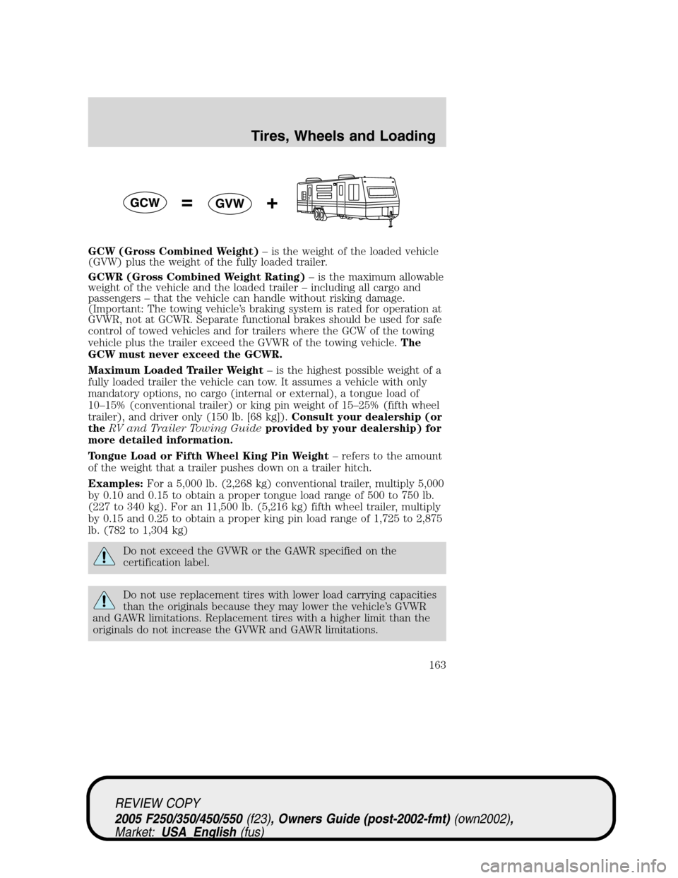
GCW (Gross Combined Weight)– is the weight of the loaded vehicle
(GVW) plus the weight of the fully loaded trailer.
GCWR (Gross Combined Weight Rating)– is the maximum allowable
weight of the vehicle and the loaded trailer – including all cargo and
passengers – that the vehicle can handle without risking damage.
(Important: The towing vehicle’s braking system is rated for operation at
GVWR, not at GCWR. Separate functional brakes should be used for safe
control of towed vehicles and for trailers where the GCW of the towing
vehicle plus the trailer exceed the GVWR of the towing vehicle.The
GCW must never exceed the GCWR.
Maximum Loaded Trailer Weight– is the highest possible weight of a
fully loaded trailer the vehicle can tow. It assumes a vehicle with only
mandatory options, no cargo (internal or external), a tongue load of
10–15% (conventional trailer) or king pin weight of 15–25% (fifth wheel
trailer), and driver only (150 lb. [68 kg]).Consult your dealership (or
theRV and Trailer Towing Guideprovided by your dealership) for
more detailed information.
Tongue Load or Fifth Wheel King Pin Weight– refers to the amount
of the weight that a trailer pushes down on a trailer hitch.
Examples:For a 5,000 lb. (2,268 kg) conventional trailer, multiply 5,000
by 0.10 and 0.15 to obtain a proper tongue load range of 500 to 750 lb.
(227 to 340 kg). For an 11,500 lb. (5,216 kg) fifth wheel trailer, multiply
by 0.15 and 0.25 to obtain a proper king pin load range of 1,725 to 2,875
lb. (782 to 1,304 kg)
Do not exceed the GVWR or the GAWR specified on the
certification label.
Do not use replacement tires with lower load carrying capacities
than the originals because they may lower the vehicle’s GVWR
and GAWR limitations. Replacement tires with a higher limit than the
originals do not increase the GVWR and GAWR limitations.
REVIEW COPY
2005 F250/350/450/550(f23), Owners Guide (post-2002-fmt)(own2002),
Market:USA_English(fus)
Tires, Wheels and Loading
163
Page 166 of 304
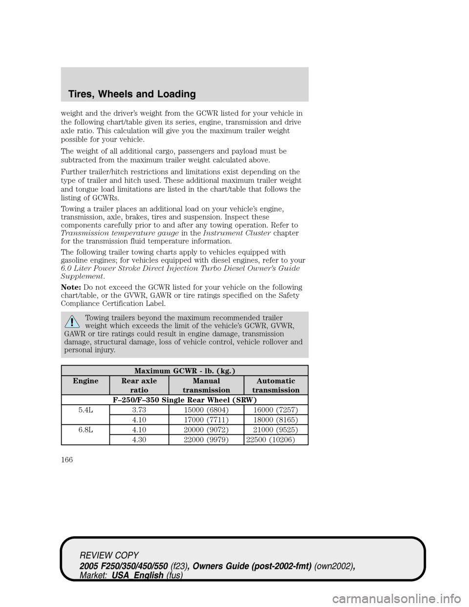
weight and the driver’s weight from the GCWR listed for your vehicle in
the following chart/table given its series, engine, transmission and drive
axle ratio. This calculation will give you the maximum trailer weight
possible for your vehicle.
The weight of all additional cargo, passengers and payload must be
subtracted from the maximum trailer weight calculated above.
Further trailer/hitch restrictions and limitations exist depending on the
type of trailer and hitch used. These additional maximum trailer weight
and tongue load limitations are listed in the chart/table that follows the
listing of GCWRs.
Towing a trailer places an additional load on your vehicle’s engine,
transmission, axle, brakes, tires and suspension. Inspect these
components carefully prior to and after any towing operation. Refer to
Transmission temperature gaugein theInstrument Clusterchapter
for the transmission fluid temperature information.
The following trailer towing charts apply to vehicles equipped with
gasoline engines; for vehicles equipped with diesel engines, refer to your
6.0 Liter Power Stroke Direct Injection Turbo Diesel Owner’s Guide
Supplement.
Note:Do not exceed the GCWR listed for your vehicle on the following
chart/table, or the GVWR, GAWR or tire ratings specified on the Safety
Compliance Certification Label.
Towing trailers beyond the maximum recommended trailer
weight which exceeds the limit of the vehicle’s GCWR, GVWR,
GAWR or tire ratings could result in engine damage, transmission
damage, structural damage, loss of vehicle control, vehicle rollover and
personal injury.
Maximum GCWR - lb. (kg.)
Engine Rear axle
ratioManual
transmissionAutomatic
transmission
F–250/F–350 Single Rear Wheel (SRW)
5.4L 3.73 15000 (6804) 16000 (7257)
4.10 17000 (7711) 18000 (8165)
6.8L 4.10 20000 (9072) 21000 (9525)
4.30 22000 (9979) 22500 (10206)
REVIEW COPY
2005 F250/350/450/550(f23), Owners Guide (post-2002-fmt)(own2002),
Market:USA_English(fus)
Tires, Wheels and Loading
166
Page 169 of 304
Trailer brakes
Electric brakes and manual, automatic or surge-type trailer brakes are
safe if installed properly and adjusted to the manufacturer’s
specifications. The trailer brakes must meet local and Federal
regulations.
Do not connect a trailer’s hydraulic brake system directly to your
vehicle’s brake system. Your vehicle may not have enough
braking power and your chances of having a collision greatly increase.
The braking system of the tow vehicle is rated for operation at the
GVWR not GCWR.
Integrated trailer brake controller (if equipped)
Your vehicle may be equipped with a fully integrated electronic Trailer
Brake Controller (TBC). The TBC assures smooth and effective trailer
braking by powering the trailer’s electric brakes with a proportional
output based on the towing vehicle’s brake pressure.
The TBC can only be used with electric trailer brakes (one to
four axles) and not surge or electric-over-hydraulic types as
these may lose trailer braking ability. It is the responsibility of the
customer to ensure that the trailer brakes are functioning properly and
all electric connections are properly made.
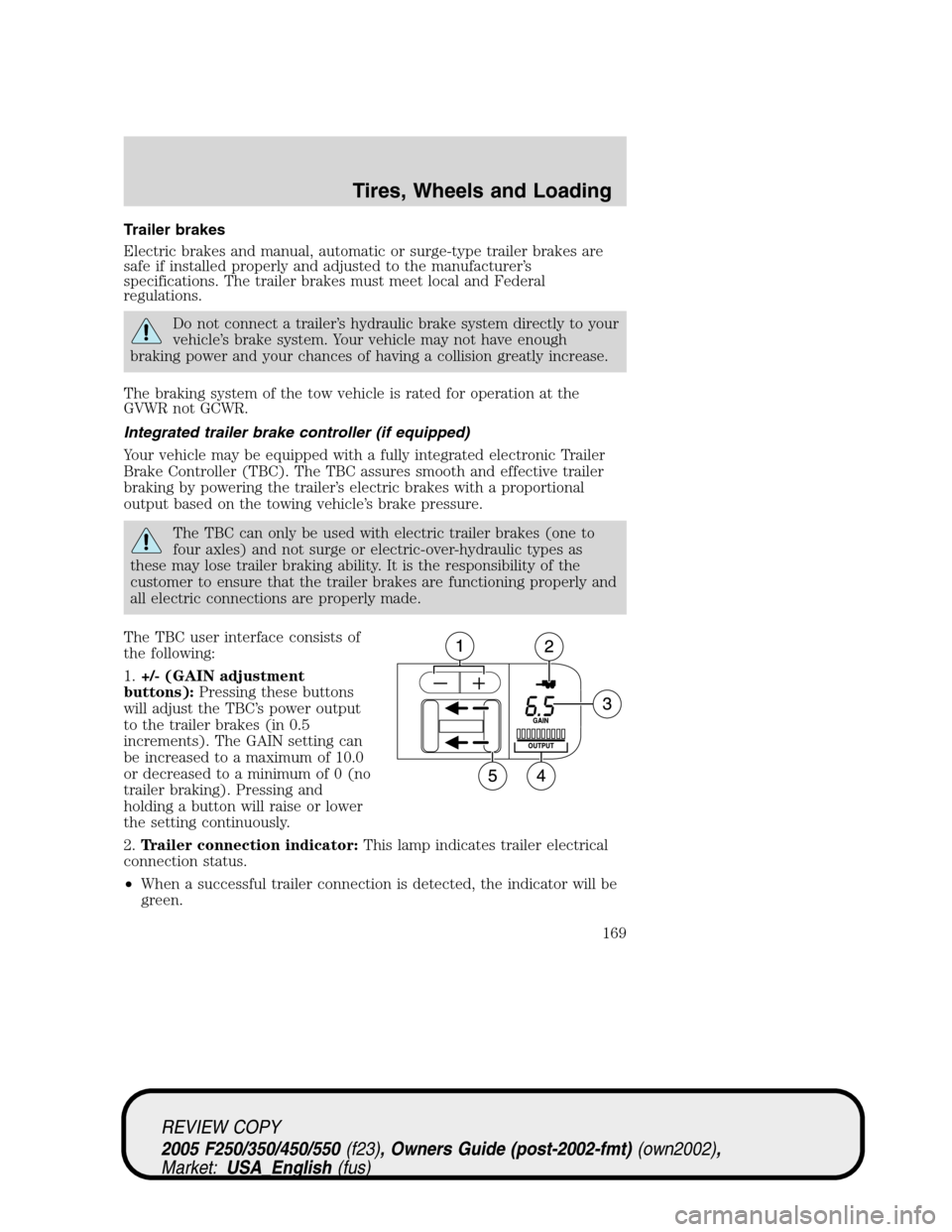
The TBC user interface consists of
the following:
1.+/- (GAIN adjustment
buttons):Pressing these buttons
will adjust the TBC’s power output
to the trailer brakes (in 0.5
increments). The GAIN setting can
be increased to a maximum of 10.0
or decreased to a minimum of 0 (no
trailer braking). Pressing and
holding a button will raise or lower
the setting continuously.
2.Trailer connection indicator:This lamp indicates trailer electrical
connection status.
•When a successful trailer connection is detected, the indicator will be
green.
REVIEW COPY
2005 F250/350/450/550(f23), Owners Guide (post-2002-fmt)(own2002),
Market:USA_English(fus)
Tires, Wheels and Loading
169
Page 170 of 304
•If the electrical connection is lost, the indicator will flash red. If the
connection is lost while the vehicle is stationary, the indicator will turn
off after 30 seconds. If the connection is lost while the vehicle is
moving, the indicator will flash until the ignition is turned off, then on
again.
•If no electrical connection is detected after the ignition is turned on,
pressing a GAIN adjustment button will display the GAIN setting.
Sliding the manual control will display the GAIN setting, OUTPUT bar
graph and light the trailer indicator red.
3.GAIN setting display:Shows the current GAIN setting. This will
illuminate when a trailer is connected, flash if the trailer becomes
disconnected, or remain off if no trailer is connected.
4.OUTPUT bar graph:When the vehicle’s brake pedal is pushed, or
when the manual control is activated, green bar indicators will illuminate
to indicate the amount of power going to the trailer brakes relative to
the brake pedal or manual control input.
5.Manual control lever:Slide the control lever to the left to activate
power to the trailer’s electric brakes independent of the tow vehicle’s
brakes. If the manual control is activated while the brake is also applied
the greater of the two inputs determines the power sent to the trailer
brakes.
•Stop Lamps:Both the tow vehicle and the trailer brake lamps will be
illuminated in the event of a manual apply using the TBC manual
control lever, as well as with any activation of the vehicle brake pedal.
GAIN
The GAIN setting is used to set the TBC for the specific towing
condition and should be changed as towing conditions change. Changes
to towing conditions include trailer load, vehicle load, road conditions
and weather.
The GAIN should be set to provide the maximum trailer braking
assistance while ensuring the trailer wheels do not lock when braking.
Locked trailer wheels may lead to trailer instability.
Procedure for adjusting GAIN:
Note:This should only be performed in a traffic free environment.
1. Make sure the trailer brakes are in good working condition and
properly adjusted; see your trailer dealer, if necessary.
2. Hook-up the trailer and make the electrical connections according to
the trailer manufacturer’s instructions.
REVIEW COPY
2005 F250/350/450/550(f23), Owners Guide (post-2002-fmt)(own2002),
Market:USA_English(fus)
Tires, Wheels and Loading
170
Page 171 of 304
3. When a trailer with electric brakes is plugged in, the trailer connection
indicator will illuminate green on the TBC and the GAIN setting display
will illuminate.
4. Use the GAIN adjustment (+/-) buttons to increase or decrease the
GAIN setting to the desired starting point. (A GAIN setting of 6.0 is a
good starting point for heavier loads.)
5. Tow the trailer on a dry, level surface at 25 mph (40 km/h) and
squeeze the manual control lever completely.
6. If the trailer wheels lock-up (indicated by squealing tires), reduce the
GAIN setting; if the wheels turn freely, increase the GAIN setting. Repeat
Steps 5 and 6 until the GAIN setting is at a point just below wheel
lock-up. If towing a heavier trailer wheel lockup may not be attainable
and the gain should be set as to achieve maximum braking force for the
specific towing conditions.
Explanation of instrument cluster messages:
The TBC interacts with the instrument cluster message center. These
messages, accompanied by a single chime, will be displayed when the
TBC determines a malfunction in the trailer connection, TBC system, or
in the trailer. These messages are listed below:
TRAILER DISCONNECTED (if equipped with message center) or
CHECK TRAILER (if equipped with mini message center):This
message is displayed when a trailer connection was determined and then
a disconnection, either intentionally or unintentionally, has been sensed
during a given ignition cycle. This message is also displayed during
manual activation without a trailer connected.
TBC FAULT: This message is displayed in response to faults sensed by
the TBC. In the event this message is seen, please take your vehicle to
an authorized Ford dealership for diagnosis and repair.
TRAILER FAULT: The TBC is capable of determining certain faults in
the trailer wiring/brake system. This message is displayed when one of
the following faults has occurred:
• Short circuit on the electric brake output wire: If the TRAILER
FAULT message is displayed with no trailer connected, the problem is
with the wiring from the TBC to the 7–pin connector in the bumper. If
the message is displayed with a trailer connected, the problem is
related to the trailer wiring; consult your trailer dealer for assistance.
• Trailer brake overload: The trailer brakes are drawing too much
current; consult your trailer dealer for assistance.
Note: Your TBC can be diagnosed by your authorized Ford dealership to
determine exactly which trailer fault has occurred; however, this
diagnosis is notcovered under your Ford warranty.
REVIEW COPY
2005 F250/350/450/550 (f23), Owners Guide (post-2002-fmt) (own2002),
Market: USA_English (fus)
Tires, Wheels and Loading
171