instrument cluster FORD SUPER DUTY 2006 1.G Diesel Supplement Manual
[x] Cancel search | Manufacturer: FORD, Model Year: 2006, Model line: SUPER DUTY, Model: FORD SUPER DUTY 2006 1.GPages: 72, PDF Size: 0.57 MB
Page 1 of 72
Introduction
2
Instrument Cluster
6
Driving
11
Roadside emergencies
18
Cleaning
24
Maintenance and Specifications
26
Scheduled Maintenance Guide
47
Normal Scheduled Maintenance and Log 51
Exceptions 59
Special Operating Conditions and Log 60
Motorcraft Premium Gold Coolant Change Record 64
All rights reserved. Reproduction by any means, electronic or mechanical
including photocopying, recording or by any information storage and retrieval
system or translation in whole or part is not permitted without written
authorization from Ford Motor Company. Ford may change the contents without
notice and without incurring obligation.
Copyright © 2005 Ford Motor Company
Table of Contents
1
2006 Econoline(eco)
Supplement
USA(fus)
Page 4 of 72
The FCM/HFCM should be drained
at regular intervals or when the
WATER IN FUEL light illuminates in
the instrument cluster.
The fuel injectors are located in the center of the combustion chambers
in the cylinder head between the rocker arm assemblies. The glow plug
system and fuel injection system are controlled through the Powertrain
Control Module (PCM) and Fuel Injection Control Module (FICM).
Fuel is drawn from the fuel tank by a frame-mounted electric fuel pump.
The fuel pump provides pressurized fuel to the engine and is
electronically controlled by the fuel pump PCM relay. The fuel pump
contains a pressure relief valve for overpressure protection in the event
of restricted flow.
Lubrication system
It is important to change the engine oil at the recommended service
intervals, because oil viscosity is important in maintaining the oil
pressure required to actuate the fuel injectors. Extended oil change
intervals can negatively affect engine performance, fuel economy and
engine life. Refer to the engine oil specification chart located under
Engine oil specificationsin theMaintenance and Specifications
chapter of this supplement.
Fast start glow plug system
The glow plug system consists of:
•eight glow plugs
•the glow plug control module (GPCM)
•engine oil temperature (EOT) sensor
•barometric pressure (BARO) sensor
The glow plug system is
electronically controlled by the
PCM. The GPCM energizes the glow
plugs immediately after the ignition
is placed in the ON position, then determines how long the glow plugs
will be on according to the EOT and BARO sensors. The required time
for the glow plugs to be energized decreases as the engine oil
temperature and barometric pressure increase.
2006 Econoline(eco)
Supplement
USA(fus)
Introduction
4
Page 6 of 72
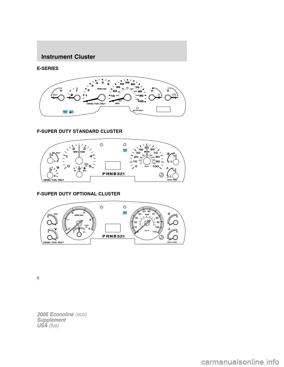
E-SERIES
F-SUPER DUTY STANDARD CLUSTER
F-SUPER DUTY OPTIONAL CLUSTER
MPHRPMX1000
km/h0 20406080
120 100140160
180L
H
E
F
DIESEL FUEL ONLY
TURBO
PSI
DPRND23
L
H
CH
SELECT/RESET
km/h11010090 80 70 50
40
30
20
10
060
2
1
0
020
40
3
4
5
2006 Econoline(eco)
Supplement
USA(fus)
Instrument Cluster
6
Page 7 of 72
Glow plug pre-heat indicator
With the key in the ON position,
the
light will illuminate if
glow plug heat is necessary as a
starting aid. Wait until the light goes
off before starting. The light should always illuminate briefly, when the
ignition key is in the ON position. If the light does not illuminate, there
may be a problem. Refer toCold weather startingin theDriving
chapter of this supplement. After the engine starts, the light should
remain off. The light should always illuminate at least momentarily when
the engine is cold and the ignition is turned to ON. If it does not
illuminate, the glow plug system should be checked and repaired
promptly to avoid difficulty in cold starting.
Waterinfuel
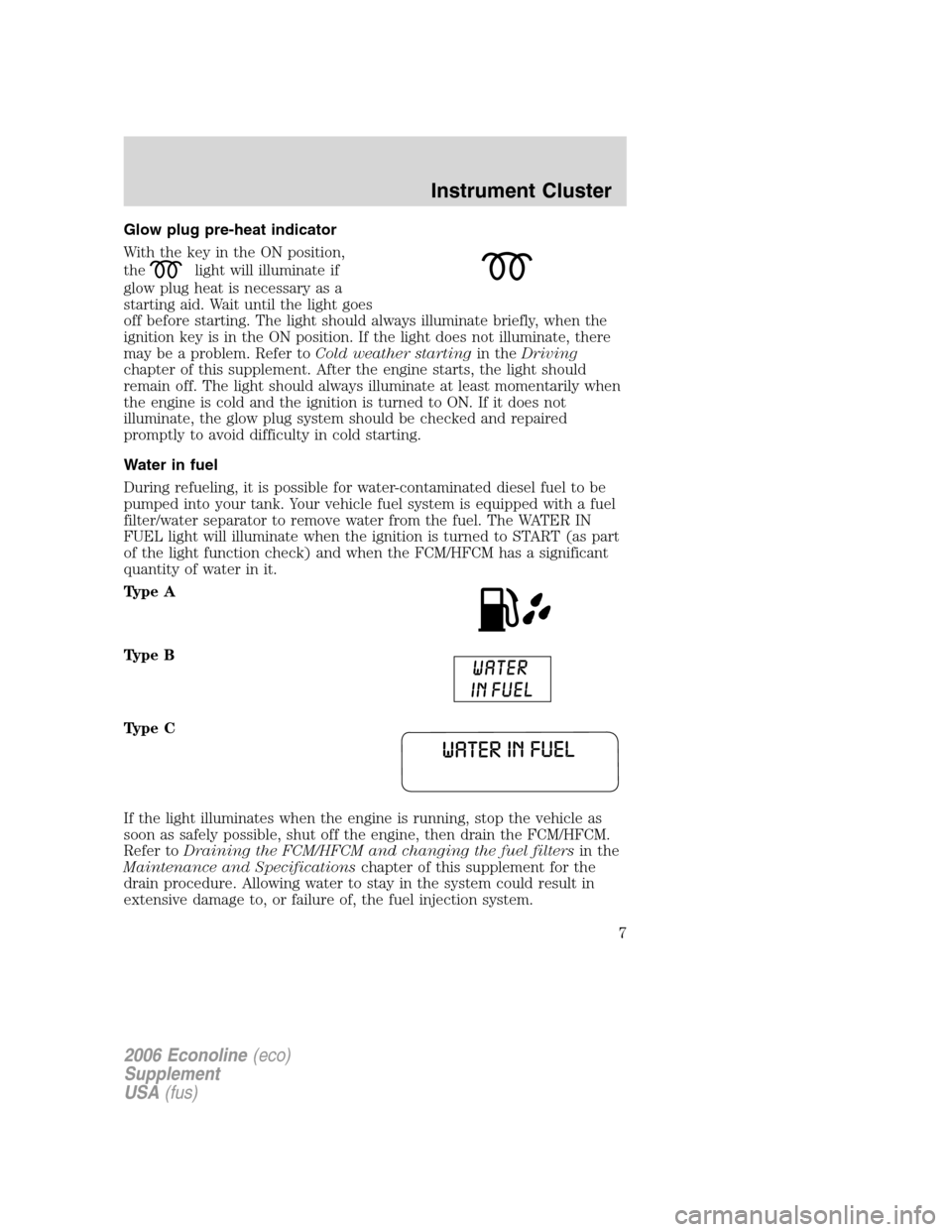
During refueling, it is possible for water-contaminated diesel fuel to be
pumped into your tank. Your vehicle fuel system is equipped with a fuel
filter/water separator to remove water from the fuel. The WATER IN
FUEL light will illuminate when the ignition is turned to START (as part
of the light function check) and when the FCM/HFCM has a significant
quantity of water in it.
Type A
Type B
Type C
If the light illuminates when the engine is running, stop the vehicle as
soon as safely possible, shut off the engine, then drain the FCM/HFCM.
Refer toDraining the FCM/HFCM and changing the fuel filtersin the
Maintenance and Specificationschapter of this supplement for the
drain procedure. Allowing water to stay in the system could result in
extensive damage to, or failure of, the fuel injection system.
2006 Econoline(eco)
Supplement
USA(fus)
Instrument Cluster
7
Page 8 of 72
Do not drain the water separator while the engine is running.
Fuel may ignite if the separator is drained while the engine is
running or the vehicle is moving.
Engine air filter (if equipped)
The engine air filter warning light illuminates when the air filter
restriction gauge reaches the CHANGE FILTER mark.
Type A
Type B
The condition should be verified by inspecting the underhood air filter
restriction gauge; the warning light is only a secondary indicator. Always
use the underhood air filter restriction gauge to determine when the air
filter element needs to be changed.
The vehicle may be driven with the engine air filter warning light
illuminated/or when the underhood air filter restriction gauge has moved
to the CHANGE FILTER mark for up to 250 miles (400 km) without
damaging the engine or related components. However, the air filter
element must be replaced at the earliest opportunity. Refer toAir filter
restriction gauge (if equipped)in this chapter for more information.
2006 Econoline(eco)
Supplement
USA(fus)
Instrument Cluster
8
Page 9 of 72
AIR FILTER RESTRICTION GAUGE (IF EQUIPPED)
The restriction gauge, located on
the upper housing of the air cleaner
assembly, measures the vacuum
inside the air cleaner. The more the
air cleaner is restricted (dirty,
clogged), the higher the vacuum
reading
Check the air filter restriction gauge
whenever the hood is raised to
perform general engine maintenance
at least every 7,500 miles (12,000 km).
If the vehicle is operated in extremely dusty conditions, check the gauge
at least every 500 miles (800 km), or two weeks, whichever comes first.
Change the air filter when the gauge reads 25 inches (635 mm). Engine
performance and fuel economy are adversely affected when the
maximum restriction is reached.
Blowing-out the air filter element with compressed air is not
recommended as the compressed air may damage the filter paper.
Note:It is not possible to determine the level of filter clogging by visual
appearance alone. A filter which appears to be dirty may actually have
several thousand miles (kilometers) of life remaining.
Always use the underhood air filter restriction gauge to
determine when the air filter element needs to be changed. The
warning light on the instrument cluster should not be used
exclusively for determining when the air filter element needs
changing.
2006 Econoline(eco)
Supplement
USA(fus)
Instrument Cluster
9
Page 10 of 72
After installation of the new filter
element, reset the gauge by pressing
the reset button on top of the
gauge.
Note:If the vehicle is operated in a
heavy snow storm, in blowing snow
or the vehicle is equipped with a
snowplow, the engine air filter
element may become partially
clogged with snow and/or ice. If this
occurs, the engine may experience a
significant reduction in power output. The vehicle may be driven under
these conditions for up to 100 miles (160 km) without damage to the
engine or related components.
At the earliest opportunity, clear all snow and ice from the air induction
system and reset the restriction gauge by pressing the button on the end
of the gauge. If the air filter restriction gauge reads 25 inches (635 mm)
after clearing snow and/or ice, then replace the filter. Reset filter
restriction gauge after changing the air filter element.
The air filter warning light on the instrument cluster may be used, in
addition to the underhood restriction gauge, to monitor the condition of
the air filter element. Refer to theEngine air filterwarning light in this
chapter of the supplement.
Engine boost gauge (if equipped)
Indicates the amount of pressure in
the engine. Driving with your
pointer continuously at the high end
of the scale may damage the engine.
2006 Econoline(eco)
Supplement
USA(fus)
Instrument Cluster
10
Page 13 of 72
Your vehicle is also equipped with a bypass relief valve, located on the
fuel control module, which provides fuel flow to the engine if the fuel
pickup should become plugged by ice or wax. To allow this bypass valve
to function and avoid engine fuel starvation, it is recommended that,
during cold weather operation 32°F (0°C) or below, the fuel level in your
tank should not be allowed to drop below
14full. This will help prevent
air from entering the fuel system and stalling the engine.
In cold weather below 32°F (0°C) your diesel engine will slowly increase
to a higher idle speed if left idling in P (Park). As the engine warms-up,
the engine sound level will decrease due to the activation of
PCM-controlled sound reduction features.
If your vehicle is operated in a heavy snow storm or blowing snow
conditions, the engine air induction may become partially clogged with
snow and/or ice. If this occurs, the engine may experience a significant
reduction in power output. At the earliest opportunity, clear all the snow
and/or ice away from the air induction inlet.
Operation in snow
Vehicle operation in heavy snowfall or in dry loose snow that may swirl
around the front of the vehicle may feed excessive amounts of snow into
the air intake system. This could plug the air cleaner with snow and
cause the engine to stall and/or lose power.
Refer toAir filter restriction gaugeandEngine air filterin the
Instrument Clusterchapter of this supplement for more information.
Operation in standing water
Ingestion of water into the diesel engine can result in immediate and
severe damage to the engine. If driving through water, slow down to
avoid splashing water into the intake. If the engine stalls, and ingestion
of water into the engine is suspected, do not try to restart the engine.
Consult your dealer for service immediately.
Engine block heater (if equipped)
Refer to theDrivingchapter in theOwner’s Guide.
2006 Econoline(eco)
Supplement
USA(fus)
Driving
13