brake FORD SUPER DUTY 2010 2.G Diesel Supplement Manual
[x] Cancel search | Manufacturer: FORD, Model Year: 2010, Model line: SUPER DUTY, Model: FORD SUPER DUTY 2010 2.GPages: 104, PDF Size: 0.63 MB
Page 11 of 104

STARTING THE ENGINE
Read all starting instructions carefully before you start your vehicle.
For temperatures below 32°F (0°C), the use of the correct grade engine
oil is essential for proper operation. Refer toEngine oil specifications
in theMaintenance and Specificationschapter for more information.
Your vehicle may be equipped with a cold weather starting strategy that
prevents severe engine damage by assisting in engine lubrication
warm-up. In extremely cold ambient temperatures, this strategy activates
and prevents the accelerator pedal from being used for 30 seconds after
starting the vehicle. By not allowing the accelerator pedal to be used, the
engine oil is allowed to properly lubricate the bearings preventing engine
damage due to lack of proper lubrication. After the 30 second warm-up
period, the accelerator pedal will be operational again as long as the
pedal is not being pressed when the 30 second time limit expires. When
starting the engine in extremely cold temperatures (-15°F [–26°C]), it is
recommended to allow the engine to idle for several minutes before
driving the vehicle.
If your vehicle is equipped with a manual transmission,make sure
the parking brake is fully set before you turn the key. Depress the clutch
pedal and place the gearshift in the neutral position. The clutch must be
fully depressed in order to operate the starter. Do not press the
accelerator during starting.
If your vehicle is equipped with an automatic transmission,ensure
the gearshift lever is in P (Park) and the parking brake is fully set before
you turn the key. Do not press the accelerator during starting.
Engine-driven cooling fan (fan clutch)
Your vehicle is equipped with an engine driven cooling fan drive (also
called a fan clutch). This fan drive changes the fan speed to match the
vehicle’s changing cooling air flow requirements. Fan speed, fan noise
level and fuel consumption all will increase based on the driving
conditions that include trailer towing, hill climbing, heavy loads, high
speed and high ambient temperature, individually or in combination. The
fan drive is designed to provide the minimum fan speed (and resulting
fan noise and fuel consumption) required to meet the ever changing
vehicle cooling air flow requirements. You will hear the amount of fan
noise increasing and decreasing as the engine power requirements and
vehicle driving conditions change as you drive. This is to be expected as
being normal to the operation of your vehicle. High levels of fan noise
might also be heard when your engine is first started, and should
normally decrease after driving for a short time.
Driving
11
2010 Econoline(eco)
Supplement(supplement), 1st Printing
USA(fus)
Page 13 of 104

ENGINE IDLE SHUTDOWN (IF EQUIPPED)
Your vehicle may be equipped with an engine idle shutdown system. This
system will automatically shut down your engine when it has been idling
in P (Park) or N (Neutral) for five minutes (parking brake set) or
15 minutes (parking brake not set). When the engine idle shutdown
process has started:
•A chime will sound and the message center will displayENGINE
TURNS OFF IN XX30 seconds prior to shutdown and begins
counting down to zero.
•The timer can be reset by changing the position of the accelerator
pedal, brake pedal or the park brake within the final 30 seconds.
•When the timer reaches zero, the engine shuts down and the message
center will displayENGINE TURNED OFF.
•One minute after the engine has shut down, the electrical system will
simulate key off, even though the ignition is still in the on position,
initiating normal accessory delay period.
•The ignition must be moved to the off position to reset the system
before restarting the vehicle.
Note:The engine idle shutdown idle timer will not start if:
•The engine is operating in power take-off (PTO) mode.
•The engine coolant temperature is below 60°F (16°C).
•The exhaust emission control device (DPF) is regenerating.
STOPPING THE ENGINE
Turn the ignition to the OFF position.
On E-Series vehicles,to prolong engine life (after extended high speed
or maximum GVW operation), it is recommended that a hot engine be
idled for 7–10 minutes which will allow the turbocharged engine to cool
down.
On F-Super Duty vehicles,to prolong engine life (especially after
extended high speed, high ambient temperature, or high GVW/GCW
operation), it is recommended that a hot engine be idled for 3-5 minutes
which will allow the turbocharged engine to cool down.
Driving
13
2010 Econoline(eco)
Supplement(supplement), 1st Printing
USA(fus)
Page 16 of 104
Idle control:
For periods of extended idle, the throttle should be set at an rpm that is
sufficient to keep the engine at normal operating temperatures. This
action can reduce the amount of engine damaging deposits.
•The engine contains a unique “Cold Weather - Idle up feature”
calibration strategy within the PCM. Under the appropriate conditions,
the strategy will automatically elevate the engine idle speed after
130 seconds of idling in cold ambient temperatures. For this feature to
be activated, the truck must be in P (Park) (for automatic
transmission), in neutral (for manual transmission) with the parking
brake applied and engine oil temperature below 158°F (70°C). This
strategy raises the rpm to a level that reduces the potential to
produce “coking” or “wet stacking”, which is common to all diesel
engines when idling for extended periods during cold ambient
temperatures.
•Your vehicle may have a factory option for a Stationary Elevated Idle
Control (SEIC) through dash-mounted Upfitter switches will allow the
operator to elevate the idle rpm for extended idle periods, as well as
aftermarket equipment such as PTO operation. This feature must be
configured even if ordered from the factory. See your authorized
dealer for required upfitting.
Operation in snow
Vehicle operation in heavy snowfall or extreme rain conditions may feed
excessive amounts of snow/water into the air intake system. This could
plug/soak the air filter with snow and may cause the engine to lose
power and possibly shut down.
You may not need to change the air filter and the vehicle may be driven
up to 200 miles (320 km) under the following conditions:
•Snow:At the earliest opportunity, open the hood and clear all the
snow and ice from the air filter housing inlet (do NOT remove the air
filter) and reset the air filter restriction gauge.
•Wet:The air filter will dry after about 15–30 minutes at highway
speeds. At the earliest opportunity, open the hood and reset the air
filter restriction gauge.
Refer toAir filter and restriction gaugein theMaintenance and
Specificationschapter of this supplement for more information.
Driving
16
2010 Econoline(eco)
Supplement(supplement), 1st Printing
USA(fus)
Page 24 of 104
JUMP STARTING YOUR VEHICLE (E-SERIES ONLY)
The following procedure is for E-Series vehicles only. F-Super
Duty vehicles equipped with the 6.4L diesel engine can be jump
started using the same procedure as a gasoline engine; refer to
yourOwner’s Guidefor the jump starting procedure.
WARNING:The gases around the battery can explode if
exposed to flames, sparks, or lit cigarettes. An explosion could
result in injury or vehicle damage.
WARNING:Batteries contain sulfuric acid which can burn skin,
eyes and clothing, if contacted.
Do not attempt to push-start your vehicle. Automatic
transmissions do not have push-start capability; damage to the
automatic transmission may result.
Preparing your vehicle
When the batteries are disconnected or new batteries are installed, the
transmission must relearn its shift strategy. As a result, the transmission
may have firm and/or soft shifts. This operation is considered normal and
will not affect function or durability of the transmission. Over time, the
adaptive learning process will fully update transmission operation.
1.Use only a 12–volt supply to start your vehicle.
2. Do not disconnect the batteries of the disabled vehicle as this could
damage the vehicle’s electrical system.
3. Park the booster vehicle close to the passenger side of the disabled
vehicle making sure the two vehiclesdo nottouch. Set the parking
brake on both vehicles.
Note:This vehicle has two frame-mounted batteries located on the
passenger side frame rail, behind the front passenger door. A battery
positive (+) jumper stud is located on the frame rail behind the rear
most battery box.
Roadside Emergencies
24
2010 Econoline(eco)
Supplement(supplement), 1st Printing
USA(fus)
Page 27 of 104
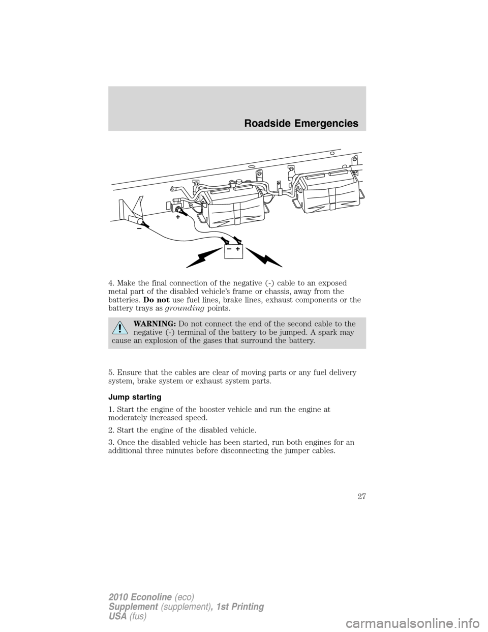
4. Make the final connection of the negative (-) cable to an exposed
metal part of the disabled vehicle’s frame or chassis, away from the
batteries.Do notuse fuel lines, brake lines, exhaust components or the
battery trays asgroundingpoints.
WARNING:Do not connect the end of the second cable to the
negative (-) terminal of the battery to be jumped. A spark may
cause an explosion of the gases that surround the battery.
5. Ensure that the cables are clear of moving parts or any fuel delivery
system, brake system or exhaust system parts.
Jump starting
1. Start the engine of the booster vehicle and run the engine at
moderately increased speed.
2. Start the engine of the disabled vehicle.
3. Once the disabled vehicle has been started, run both engines for an
additional three minutes before disconnecting the jumper cables.
Roadside Emergencies
27
2010 Econoline(eco)
Supplement(supplement), 1st Printing
USA(fus)
Page 33 of 104
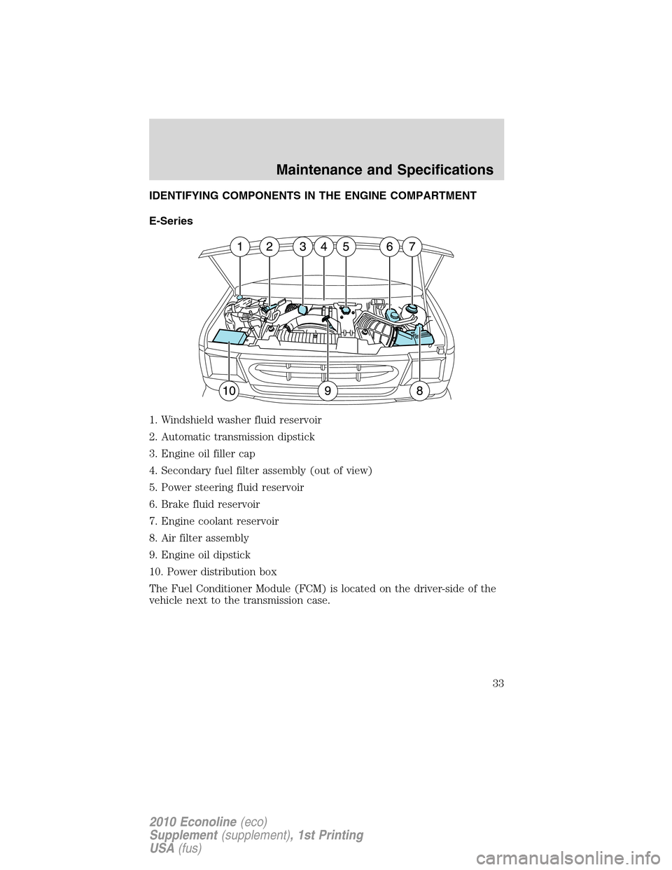
IDENTIFYING COMPONENTS IN THE ENGINE COMPARTMENT
E-Series
1. Windshield washer fluid reservoir
2. Automatic transmission dipstick
3. Engine oil filler cap
4. Secondary fuel filter assembly (out of view)
5. Power steering fluid reservoir
6. Brake fluid reservoir
7. Engine coolant reservoir
8. Air filter assembly
9. Engine oil dipstick
10. Power distribution box
The Fuel Conditioner Module (FCM) is located on the driver-side of the
vehicle next to the transmission case.
Maintenance and Specifications
33
2010 Econoline(eco)
Supplement(supplement), 1st Printing
USA(fus)
Page 34 of 104
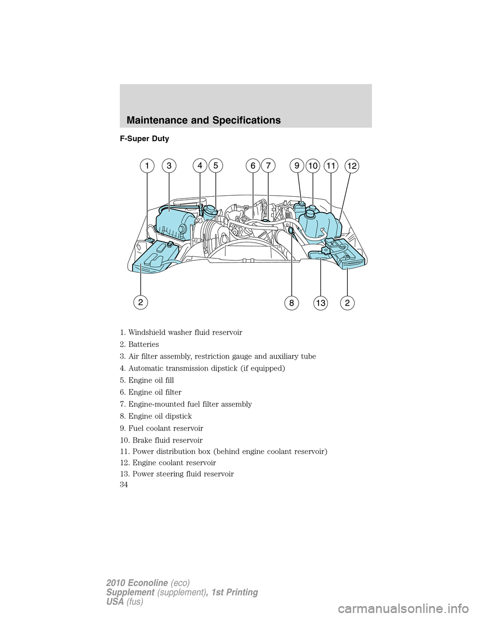
F-Super Duty
1. Windshield washer fluid reservoir
2. Batteries
3. Air filter assembly, restriction gauge and auxiliary tube
4. Automatic transmission dipstick (if equipped)
5. Engine oil fill
6. Engine oil filter
7. Engine-mounted fuel filter assembly
8. Engine oil dipstick
9. Fuel coolant reservoir
10. Brake fluid reservoir
11. Power distribution box (behind engine coolant reservoir)
12. Engine coolant reservoir
13. Power steering fluid reservoir
Maintenance and Specifications
34
2010 Econoline(eco)
Supplement(supplement), 1st Printing
USA(fus)
Page 64 of 104
Genuine Ford and Motorcraft Replacement Parts
Ford dealerships stock Ford and Motorcraft branded replacement parts.
These parts meet or exceed Ford Motor Company’s specifications, and
we stand behind them. Maintenance parts installed at your Ford
dealership carry a nationwide, 12 months, 12,000 mile (20,000 km) parts
and labor limited warranty. Your dealer can give you details.
Value Shopping for Your Vehicle’s Maintenance Needs
Your dealership recognizes the competitive landscape of maintenance and
light repair automotive services. With factory-trained technicians, and
one-stop service from routine maintenance like oil changes and tire
rotations to repairs like brake service, check out the value your Ford
dealers can offer.
WHICH MAINTENANCE SCHEDULE SHOULD YOU FOLLOW?
Owner Checks and Services
Refer to Mileage Intervals for Additional Checks and Services
Certain basic maintenance checks and inspections should be performed
by the owner or a service technician at the intervals indicated. Service
information and supporting specifications are provided in theOwner’s
Guide.
Any adverse condition should be brought to the attention of your dealer
or qualified service technician as soon as possible for the proper service
advice. The owner maintenance service checks are generally not covered
by warranties so you may be charged for labor, parts or lubricants used.
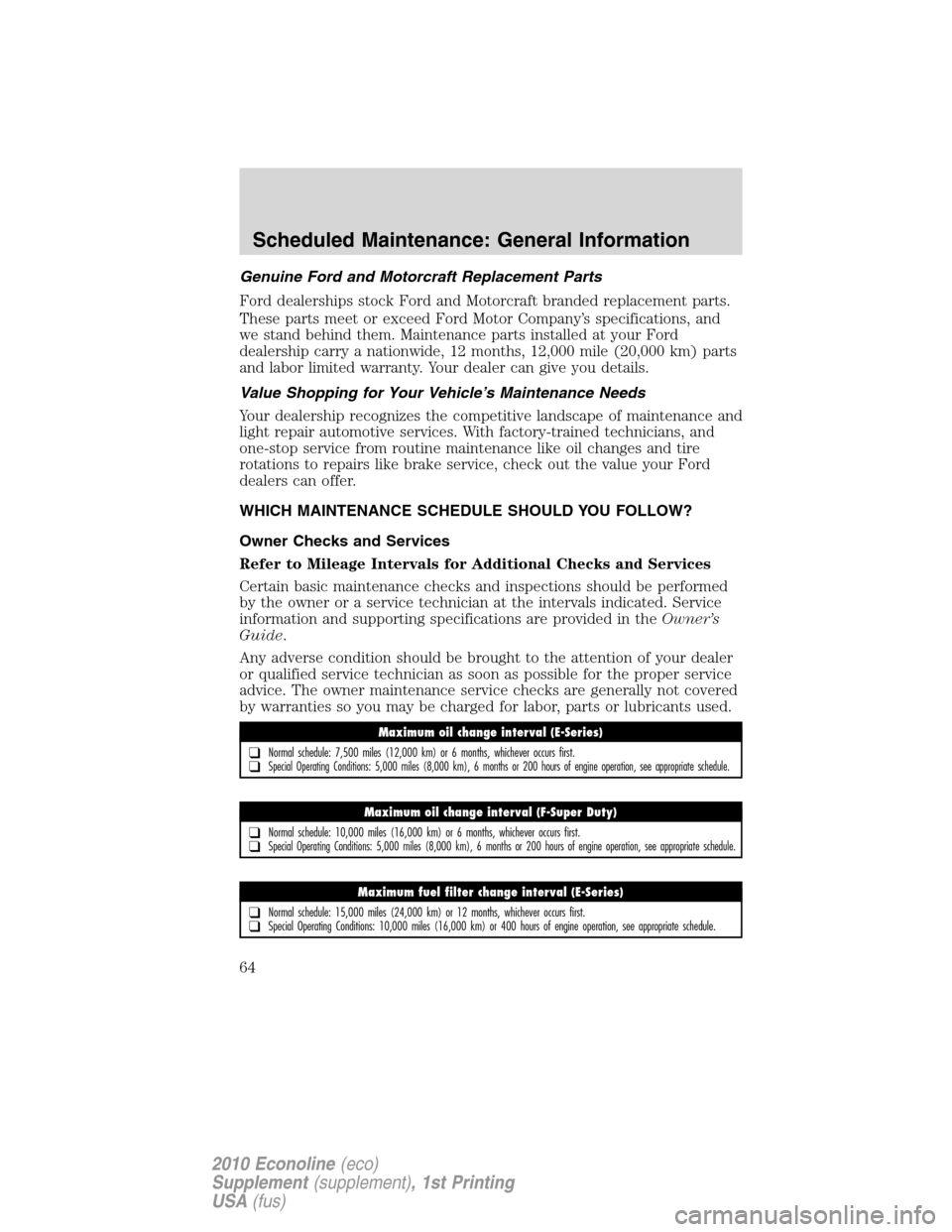
Maximum oil change interval (E-Series)
❑Normal schedule: 7,500 miles (12,000 km) or 6 months, whichever occurs first.❑Special Operating Conditions: 5,000 miles (8,000 km), 6 months or 200 hours of engine operation, see appropriate schedule.
Maximum oil change interval (F-Super Duty)
❑Normal schedule: 10,000 miles (16,000 km) or 6 months, whichever occurs first.❑Special Operating Conditions: 5,000 miles (8,000 km), 6 months or 200 hours of engine operation, see appropriate schedule.
Maximum fuel filter change interval (E-Series)
❑Normal schedule: 15,000 miles (24,000 km) or 12 months, whichever occurs first.❑Special Operating Conditions: 10,000 miles (16,000 km) or 400 hours of engine operation, see appropriate schedule.
Scheduled Maintenance: General Information
64
2010 Econoline(eco)
Supplement(supplement), 1st Printing
USA(fus)
Page 65 of 104
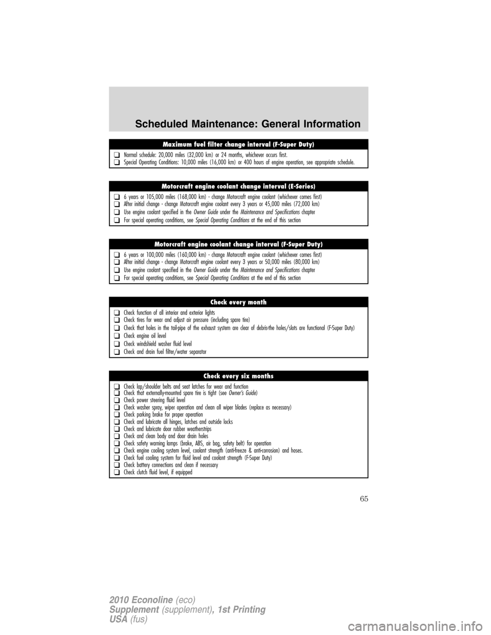
Maximum fuel filter change interval (F-Super Duty)
❑Normal schedule: 20,000 miles (32,000 km) or 24 months, whichever occurs first.❑Special Operating Conditions: 10,000 miles (16,000 km) or 400 hours of engine operation, see appropriate schedule.
Motorcraft engine coolant change interval (E-Series)
❑6 years or 105,000 miles (168,000 km) - change Motorcraft engine coolant (whichever comes first)❑After initial change - change Motorcraft engine coolant every 3 years or 45,000 miles (72,000 km)
❑Use engine coolant specified in theOwner Guideunder theMaintenance and Specificationschapter
❑For special operating conditions, seeSpecial Operating Conditionsat the end of this section
Motorcraft engine coolant change interval (F-Super Duty)
❑6 years or 100,000 miles (160,000 km) - change Motorcraft engine coolant (whichever comes first)❑After initial change - change Motorcraft engine coolant every 3 years or 50,000 miles (80,000 km)
❑Use engine coolant specified in theOwner Guideunder theMaintenance and Specificationschapter
❑For special operating conditions, seeSpecial Operating Conditionsat the end of this section
Check every month
❑Check function of all interior and exterior lights❑Check tires for wear and adjust air pressure (including spare tire)
❑Check that holes in the tail-pipe of the exhaust system are clear of debris-the holes/slots are functional (F-Super Duty)
❑Check engine oil level
❑Check windshield washer fluid level
❑Check and drain fuel filter/water separator
Check every six months
❑Check lap/shoulder belts and seat latches for wear and function❑Check that externally-mounted spare tire is tight (seeOwner’s Guide)❑Check power steering fluid level❑Check washer spray, wiper operation and clean all wiper blades (replace as necessary)❑Check parking brake for proper operation❑Check and lubricate all hinges, latches and outside locks❑Check and lubricate door rubber weatherstrips❑Check and clean body and door drain holes❑Check safety warning lamps (brake, ABS, air bag, safety belt) for operation❑Check engine cooling system level, coolant strength (anti-freeze & anti-corrosion) and hoses.❑Check fuel cooling system for fluid level and coolant strength (F-Super Duty)❑Check battery connections and clean if necessary❑Check clutch fluid level, if equipped
Scheduled Maintenance: General Information
65
2010 Econoline(eco)
Supplement(supplement), 1st Printing
USA(fus)
Page 66 of 104
Multi-point Inspection
In order to keep your vehicle running right, it is important that you have
the systems on your vehicle checked regularly. This can help identify any
potential issue before there are any problems. Ford Motor Company
suggests the following multi-point inspection to be performed at every
scheduled maintenance interval as the way to ensure your vehicle keeps
running right.
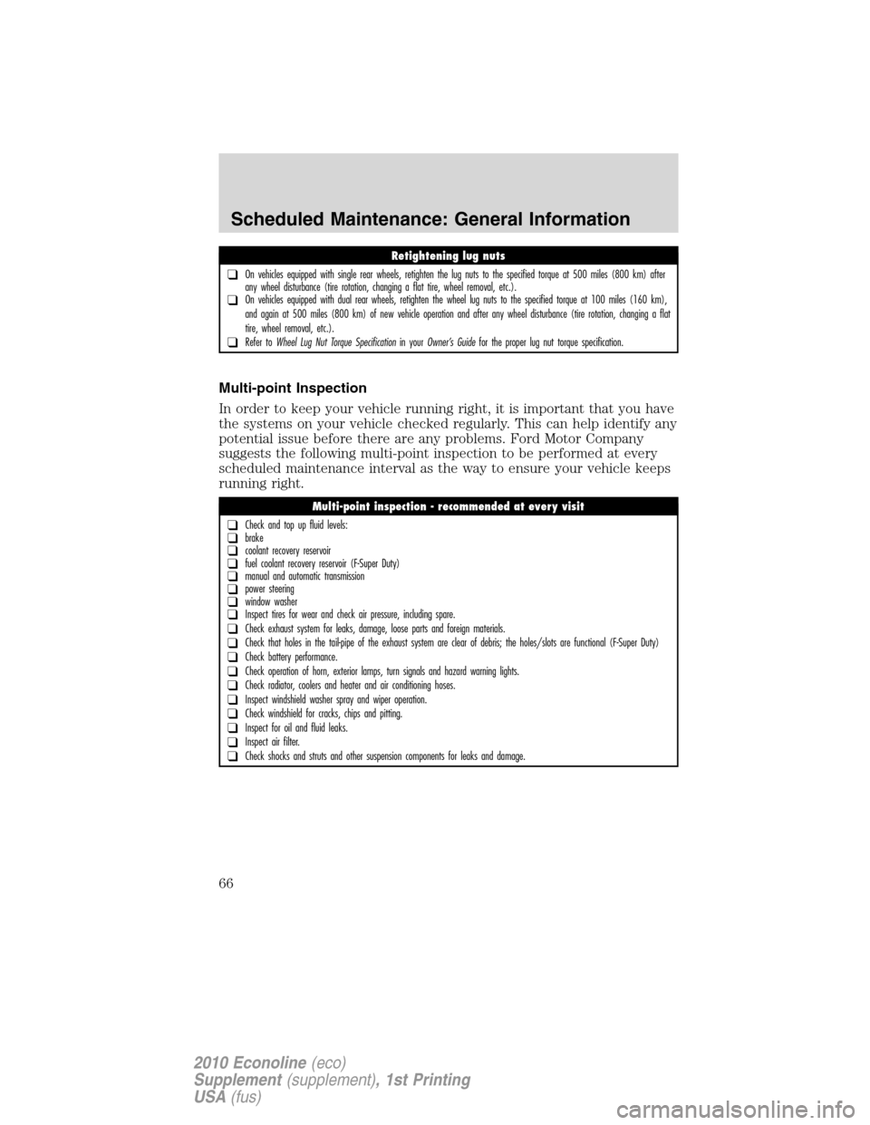
Retightening lug nuts
❑On vehicles equipped with single rear wheels, retighten the lug nuts to the specified torque at 500 miles (800 km) after
any wheel disturbance (tire rotation, changing a flat tire, wheel removal, etc.).
❑On vehicles equipped with dual rear wheels, retighten the wheel lug nuts to the specified torque at 100 miles (160 km),
and again at 500 miles (800 km) of new vehicle operation and after any wheel disturbance (tire rotation, changing a flat
tire, wheel removal, etc.).
❑Refer toWheel Lug Nut Torque Specificationin yourOwner’s Guidefor the proper lug nut torque specification.
Multi-point inspection - recommended at every visit
❑Check and top up fluid levels:❑brake❑coolant recovery reservoir❑fuel coolant recovery reservoir (F-Super Duty)❑manual and automatic transmission❑power steering❑window washer❑Inspect tires for wear and check air pressure, including spare.
❑Check exhaust system for leaks, damage, loose parts and foreign materials.
❑Check that holes in the tail-pipe of the exhaust system are clear of debris; the holes/slots are functional (F-Super Duty)
❑Check battery performance.
❑Check operation of horn, exterior lamps, turn signals and hazard warning lights.
❑Check radiator, coolers and heater and air conditioning hoses.
❑Inspect windshield washer spray and wiper operation.
❑Check windshield for cracks, chips and pitting.
❑Inspect for oil and fluid leaks.
❑Inspect air filter.
❑Check shocks and struts and other suspension components for leaks and damage.
Scheduled Maintenance: General Information
66
2010 Econoline(eco)
Supplement(supplement), 1st Printing
USA(fus)