tow bar FORD SUPER DUTY 2016 3.G Owners Manual
[x] Cancel search | Manufacturer: FORD, Model Year: 2016, Model line: SUPER DUTY, Model: FORD SUPER DUTY 2016 3.GPages: 510, PDF Size: 5.42 MB
Page 63 of 510
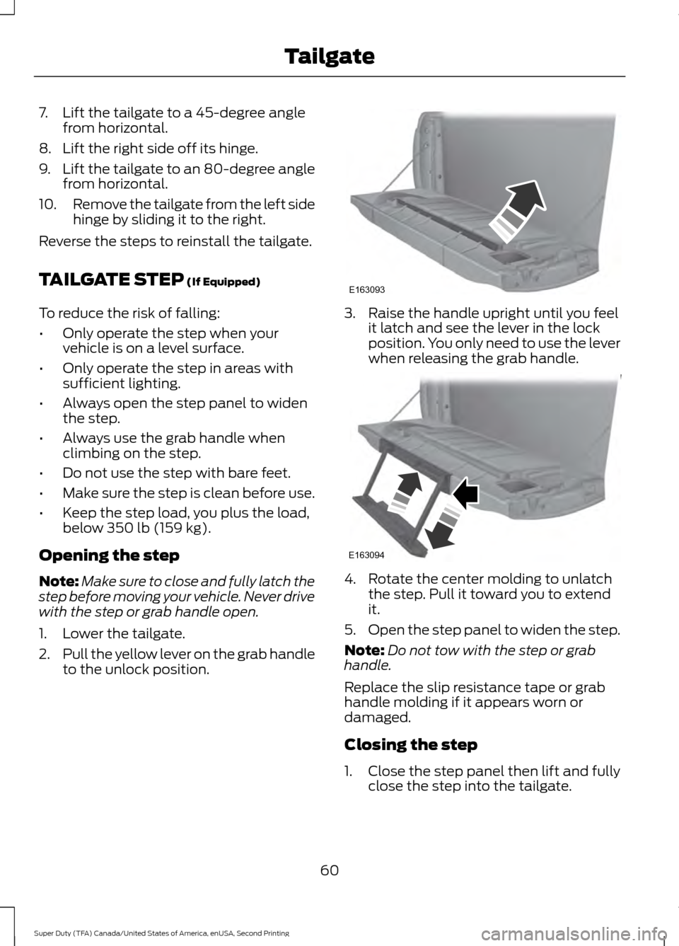
7. Lift the tailgate to a 45-degree angle
from horizontal.
8. Lift the right side off its hinge.
9. Lift the tailgate to an 80-degree angle
from horizontal.
10. Remove the tailgate from the left side
hinge by sliding it to the right.
Reverse the steps to reinstall the tailgate.
TAILGATE STEP (If Equipped)
To reduce the risk of falling:
• Only operate the step when your
vehicle is on a level surface.
• Only operate the step in areas with
sufficient lighting.
• Always open the step panel to widen
the step.
• Always use the grab handle when
climbing on the step.
• Do not use the step with bare feet.
• Make sure the step is clean before use.
• Keep the step load, you plus the load,
below
350 lb (159 kg).
Opening the step
Note: Make sure to close and fully latch the
step before moving your vehicle. Never drive
with the step or grab handle open.
1. Lower the tailgate.
2. Pull the yellow lever on the grab handle
to the unlock position. 3. Raise the handle upright until you feel
it latch and see the lever in the lock
position. You only need to use the lever
when releasing the grab handle. 4. Rotate the center molding to unlatch
the step. Pull it toward you to extend
it.
5. Open the step panel to widen the step.
Note: Do not tow with the step or grab
handle.
Replace the slip resistance tape or grab
handle molding if it appears worn or
damaged.
Closing the step
1. Close the step panel then lift and fully close the step into the tailgate.
60
Super Duty (TFA) Canada/United States of America, enUSA, Second Printing TailgateE163093 E163094
Page 98 of 510
Fuel Hist.
Shows fuel usage as a bar graph based on
time. The graph is updated each minute
with the fuel economy that was achieved
during the prior 5, 10, 30 minutes of driving.
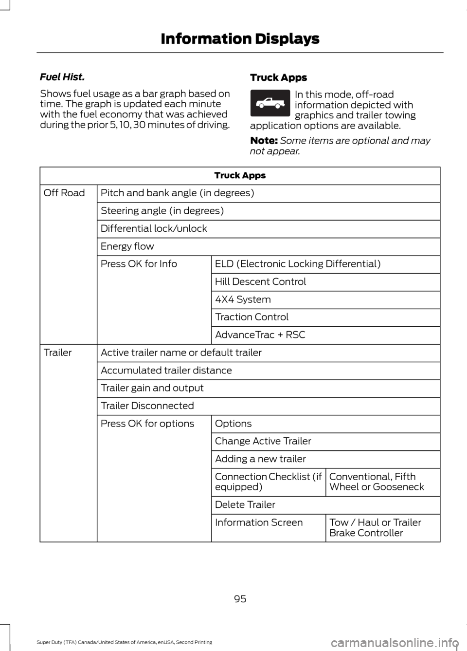
Truck Apps In this mode, off-road
information depicted with
graphics and trailer towing
application options are available.
Note: Some items are optional and may
not appear. Truck Apps
Pitch and bank angle (in degrees)
Off Road
Steering angle (in degrees)
Differential lock/unlock
Energy flow ELD (Electronic Locking Differential)
Press OK for Info
Hill Descent Control
4X4 System
Traction Control
AdvanceTrac + RSC
Active trailer name or default trailer
Trailer
Accumulated trailer distance
Trailer gain and output
Trailer Disconnected Options
Press OK for options
Change Active Trailer
Adding a new trailerConventional, Fifth
Wheel or Gooseneck
Connection Checklist (if
equipped)
Delete Trailer
Tow / Haul or Trailer
Brake Controller
Information Screen
95
Super Duty (TFA) Canada/United States of America, enUSA, Second Printing Information DisplaysE163181
Page 197 of 510
Chassis cab
MaximumGCWR
Rear axle ratio
Engine
Vehicle
26000 lb (11793kg)
4.88
6.7L diesel
35000 lb (15875
kg)*
* Requires optional GCWR Package.
Calculating the Maximum
Loaded Trailer Weight for Your
Vehicle
1. Start with the gross combined weight rating for your vehicle
model and axle ratio. See the
previous chart.
2. Subtract all of the following
that apply to your vehicle:
• Vehicle curb weight
• Hitch hardware weight, such as
a draw bar, ball, locks or weight
distributing hardware
• Driver weight
• Passenger(s) weight
• Payload, cargo and luggage
weight
• Aftermarket equipment weight.
This equals the maximum loaded
trailer weight for this combination.
Note: The trailer tongue load is
considered part of the payload for
your vehicle. Reduce the total
payload by the final trailer tongue
weight. Note:
Consult an authorized dealer
to determine the maximum trailer
weight allowed for your vehicle if
you are not sure.
ESSENTIAL TOWING CHECKS WARNING
Do not exceed the lesser of your
vehicle or trailer hitch rating. Rating
will vary depending on vehicle
equipment. Vehicle stability and handling
can be impaired if your vehicle or trailer
hitch is over-loaded. Do not cut, drill, weld
or modify trailer hitches. Modifying trailer
hitches can reduce hitch rating. Serious
injury or death can result from over-loading
your vehicle or trailer hitch. Follow these guidelines for safe towing:
•
Do not tow a trailer until you drive your
vehicle at least 1,000 mi (1,600 km).
• Consult your local motor vehicle laws
for towing a trailer.
• See the instructions included with
towing accessories for the proper
installation and adjustment
specifications.
194
Super Duty (TFA) Canada/United States of America, enUSA, Second Printing Towing
Page 200 of 510
When hooking-up a trailer using a
weight-distributing hitch, always use the
following procedure:
1. Park the loaded vehicle, without the
trailer, on a level surface.
2. Measure the height to the top of your vehicle's front wheel opening on the
fender. This is H1.
3. Attach the loaded trailer to your vehicle
without the weight-distributing bars
connected.
4. Measure the height to the top of your vehicle's front wheel opening on the
fender a second time. This is H2.
5. Install and adjust the tension in the weight-distributing bars so that the
height of your vehicle's front wheel
opening on the fender is approximately
halfway between H1 and H2.
6. Check that the trailer is level or slightly
nose down toward your vehicle. If not,
adjust the ball height accordingly and
repeat Steps 2-6.
Once the trailer is level or slightly nose
down toward the vehicle:
• Lock the bar tension adjuster in place.
• Check that the trailer tongue securely
attaches and locks onto the hitch.
• Install safety chains, lighting, and trailer
brake controls as required by law or the
trailer manufacturer. Fifth-wheel Trailer Hitch (If Equipped) WARNING
The mounting pads in the bed are
specifically designed for certain
fifth-wheel trailer hitches and
gooseneck ball hitches. Do not use these
mounting pads for other purposes. Doing
so could result in vehicle structural
damage, loss of vehicle control, and
personal injury. Contact an authorized
dealer to purchase gooseneck and
fifth-wheel hitches that are compatible
with your vehicle. Your vehicle may be equipped with a
fifth-wheel prep package. This package
enables your vehicle to accept certain
fifth-wheel trailer hitches and gooseneck
ball hitches. The fifth-wheel trailer hitch
attaches to the four mounting pads in the
pick-up bed. An optional 7-pin trailer wiring
connector may be in the bed as well. The
gooseneck ball hitch is a separate
mounting pad from the fifth-wheel hitch,
located in the center of the bed.
Shorter pick-up boxes, such as the 6½-foot
box on the F-250 and F-350, provide less
clearance between the cab and the
fifth-wheel and gooseneck trailer
compared to longer box pick-ups, such as
an 8-foot box on the F-250 or F-350. When
selecting a trailer and tow vehicle, it is
critical to check that this combination
provides clearance between the front of
the trailer and tow vehicle for turns up to
90 degrees. Failure to follow this
recommendation could result in the trailer
contacting the cab of the tow vehicle
during tight turns that are typical during
low-speed parking and turning maneuvers.
This contact could result in damage to the
trailer and tow vehicle.
197
Super Duty (TFA) Canada/United States of America, enUSA, Second Printing Towing
Page 202 of 510
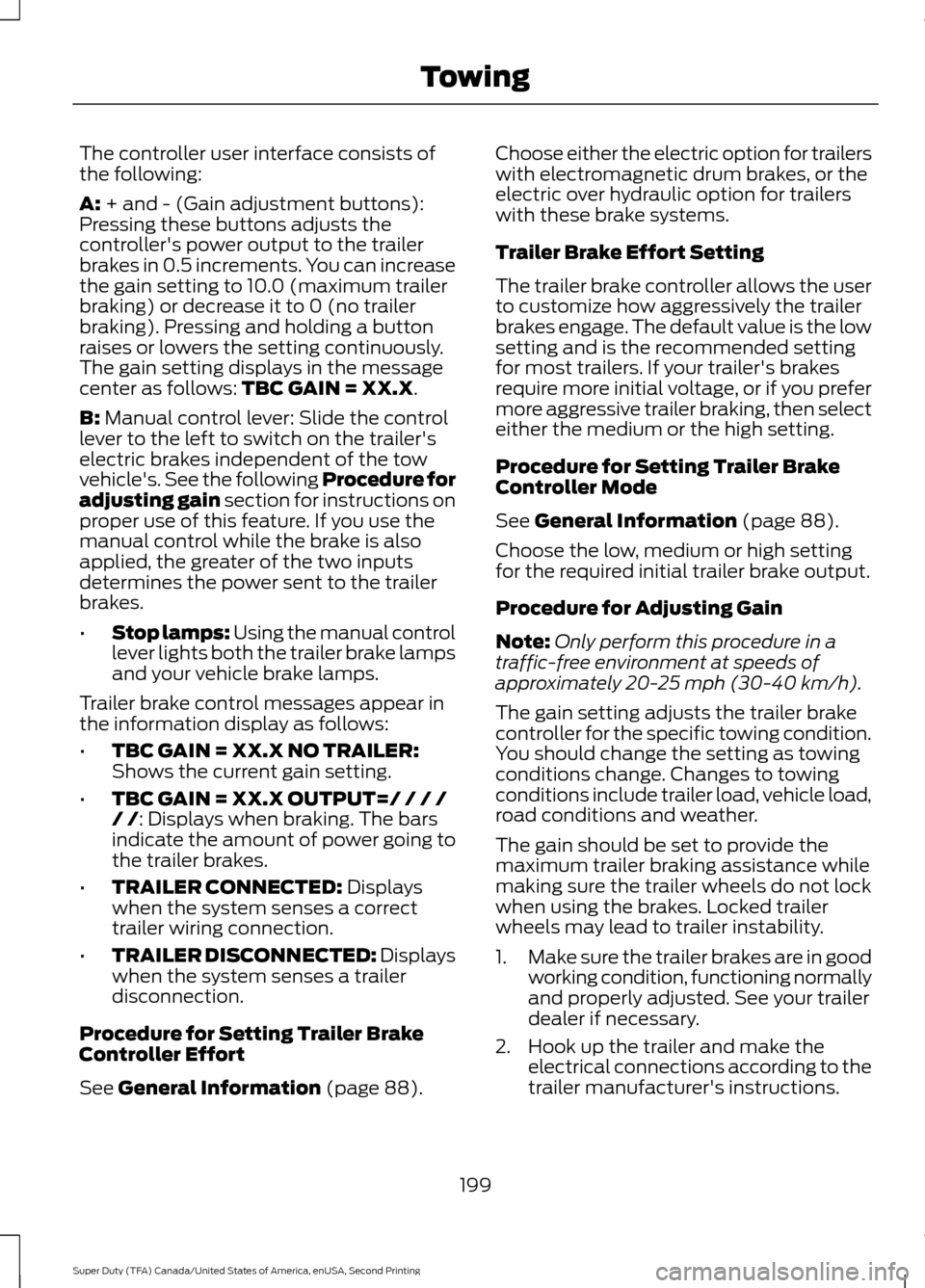
The controller user interface consists of
the following:
A: + and - (Gain adjustment buttons):
Pressing these buttons adjusts the
controller's power output to the trailer
brakes in 0.5 increments. You can increase
the gain setting to 10.0 (maximum trailer
braking) or decrease it to 0 (no trailer
braking). Pressing and holding a button
raises or lowers the setting continuously.
The gain setting displays in the message
center as follows:
TBC GAIN = XX.X.
B:
Manual control lever: Slide the control
lever to the left to switch on the trailer's
electric brakes independent of the tow
vehicle's. See the following Procedure for
adjusting gain section for instructions on
proper use of this feature. If you use the
manual control while the brake is also
applied, the greater of the two inputs
determines the power sent to the trailer
brakes.
• Stop lamps: Using the manual control
lever lights both the trailer brake lamps
and your vehicle brake lamps.
Trailer brake control messages appear in
the information display as follows:
• TBC GAIN = XX.X NO TRAILER:
Shows the current gain setting.
• TBC GAIN = XX.X OUTPUT=/ / / /
/ /
: Displays when braking. The bars
indicate the amount of power going to
the trailer brakes.
• TRAILER CONNECTED:
Displays
when the system senses a correct
trailer wiring connection.
• TRAILER DISCONNECTED: Displays
when the system senses a trailer
disconnection.
Procedure for Setting Trailer Brake
Controller Effort
See
General Information (page 88). Choose either the electric option for trailers
with electromagnetic drum brakes, or the
electric over hydraulic option for trailers
with these brake systems.
Trailer Brake Effort Setting
The trailer brake controller allows the user
to customize how aggressively the trailer
brakes engage. The default value is the low
setting and is the recommended setting
for most trailers. If your trailer's brakes
require more initial voltage, or if you prefer
more aggressive trailer braking, then select
either the medium or the high setting.
Procedure for Setting Trailer Brake
Controller Mode
See
General Information (page 88).
Choose the low, medium or high setting
for the required initial trailer brake output.
Procedure for Adjusting Gain
Note: Only perform this procedure in a
traffic-free environment at speeds of
approximately 20-25 mph (30-40 km/h).
The gain setting adjusts the trailer brake
controller for the specific towing condition.
You should change the setting as towing
conditions change. Changes to towing
conditions include trailer load, vehicle load,
road conditions and weather.
The gain should be set to provide the
maximum trailer braking assistance while
making sure the trailer wheels do not lock
when using the brakes. Locked trailer
wheels may lead to trailer instability.
1. Make sure the trailer brakes are in good
working condition, functioning normally
and properly adjusted. See your trailer
dealer if necessary.
2. Hook up the trailer and make the electrical connections according to the
trailer manufacturer's instructions.
199
Super Duty (TFA) Canada/United States of America, enUSA, Second Printing Towing
Page 209 of 510
BREAKING-IN
You need to break in new tires for
approximately 300 miles (480
kilometers). During this time, your vehicle
may exhibit some unusual driving
characteristics.
Avoid driving too fast during the first 1000
miles (1600 kilometers). Vary your speed
frequently and change up through the
gears early. Do not labor the engine.
Do not tow during the first 1000 miles
(1600 kilometers).
ECONOMICAL DRIVING
Your fuel economy is affected by several
things, such as how you drive, the
conditions you drive under, and how you
maintain your vehicle.
You may improve your fuel economy by
keeping these things in mind:
•
Accelerate and slow down in a smooth,
moderate fashion.
• Drive at steady speeds without
stopping.
• Anticipate stops; slowing down may
eliminate the need to stop.
• Combine errands and minimize
stop-and-go driving.
• Close the windows for high-speed
driving.
• Drive at reasonable speeds (traveling
at 55 mph [88 km/h] uses 15% less
fuel than traveling at 65 mph [105
km/h]).
• Keep the tires properly inflated and use
only the recommended size.
• Use the recommended engine oil.
• Perform all regularly scheduled
maintenance. Avoid these actions; they reduce your fuel
economy:
•
Sudden accelerations or hard
accelerations.
• Revving the engine before turning it off.
• Idle for periods longer than one minute.
• Warm up your vehicle on cold
mornings.
• Use the air conditioner or front
defroster.
• Use the speed control in hilly terrain.
• Rest your foot on the brake pedal while
driving.
• Drive a heavily loaded vehicle or tow a
trailer.
• Carry unnecessary weight
(approximately 1 mpg [0.4 km/L] is
lost for every 400 lb [180 kilogram] of
weight carried).
• Driving with the wheels out of
alignment.
Conditions
• Heavily loading a vehicle or towing a
trailer may reduce fuel economy at any
speed.
• Adding certain accessories to your
vehicle (for example bug deflectors,
rollbars, light bars, running boards, ski
racks or luggage racks) may reduce
fuel economy.
• To maximize the fuel economy, drive
with the tonneau cover installed (if
equipped).
• Using fuel blended with alcohol may
lower fuel economy.
• Fuel economy may decrease with lower
temperatures during the first 8– 10
miles (12 –16 kilometers) of driving.
• Driving on flat terrain offers improved
fuel economy as compared to driving
on hilly terrain.
206
Super Duty (TFA) Canada/United States of America, enUSA, Second Printing Driving Hints
Page 227 of 510
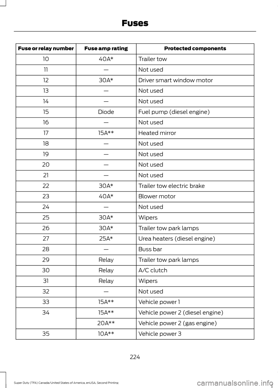
Protected components
Fuse amp rating
Fuse or relay number
Trailer tow
40A*
10
Not used
—
11
Driver smart window motor
30A*
12
Not used
—
13
Not used
—
14
Fuel pump (diesel engine)
Diode
15
Not used
—
16
Heated mirror
15A**
17
Not used
—
18
Not used
—
19
Not used
—
20
Not used
—
21
Trailer tow electric brake
30A*
22
Blower motor
40A*
23
Not used
—
24
Wipers
30A*
25
Trailer tow park lamps
30A*
26
Urea heaters (diesel engine)
25A*
27
Buss bar
—
28
Trailer tow park lamps
Relay
29
A/C clutch
Relay
30
Wipers
Relay
31
Not used
—
32
Vehicle power 1
15A**
33
Vehicle power 2 (diesel engine)
15A**
34
Vehicle power 2 (gas engine)
20A**
Vehicle power 3
10A**
35
224
Super Duty (TFA) Canada/United States of America, enUSA, Second Printing Fuses
Page 232 of 510
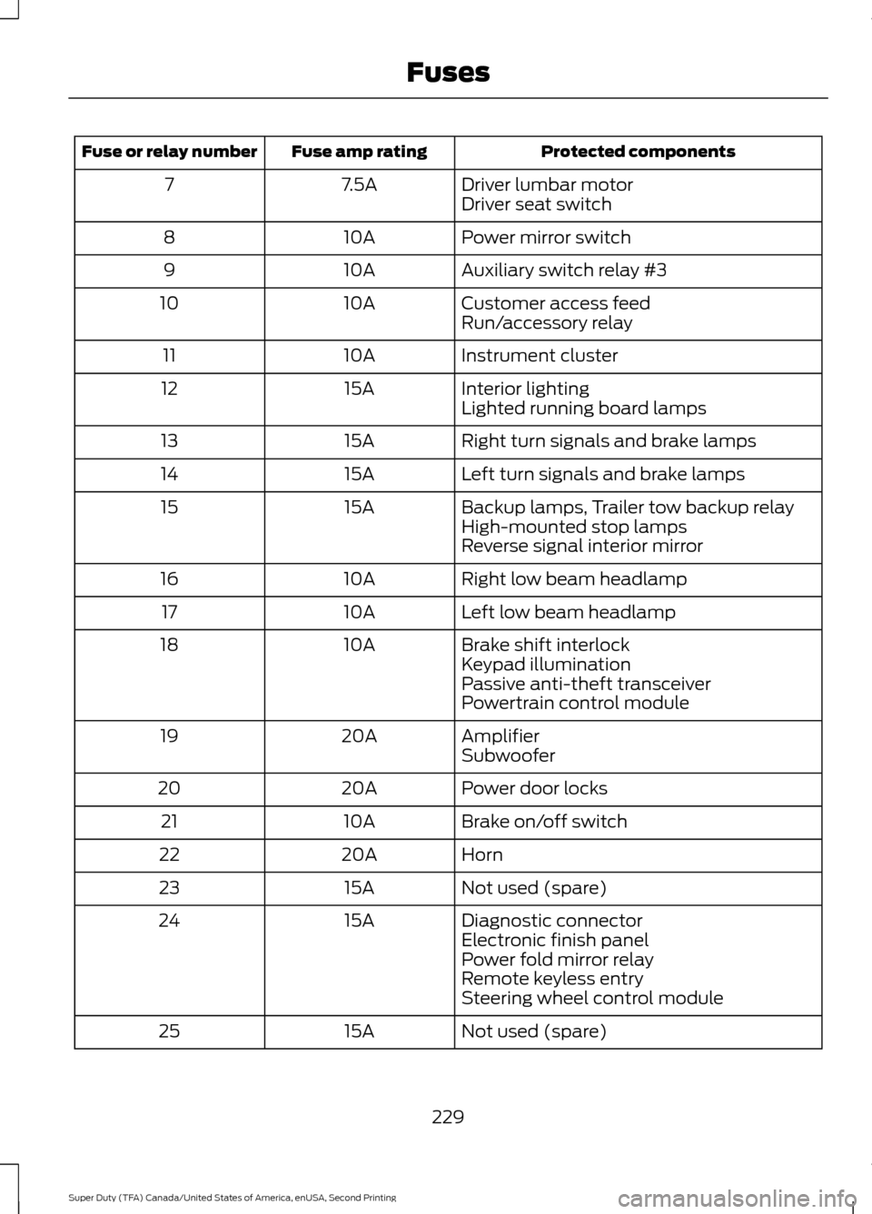
Protected components
Fuse amp rating
Fuse or relay number
Driver lumbar motor
7.5A
7
Driver seat switch
Power mirror switch
10A
8
Auxiliary switch relay #3
10A
9
Customer access feed
10A
10
Run/accessory relay
Instrument cluster
10A
11
Interior lighting
15A
12
Lighted running board lamps
Right turn signals and brake lamps
15A
13
Left turn signals and brake lamps
15A
14
Backup lamps, Trailer tow backup relay
15A
15
High-mounted stop lamps
Reverse signal interior mirror
Right low beam headlamp
10A
16
Left low beam headlamp
10A
17
Brake shift interlock
10A
18
Keypad illumination
Passive anti-theft transceiver
Powertrain control module
Amplifier
20A
19
Subwoofer
Power door locks
20A
20
Brake on/off switch
10A
21
Horn
20A
22
Not used (spare)
15A
23
Diagnostic connector
15A
24
Electronic finish panel
Power fold mirror relay
Remote keyless entry
Steering wheel control module
Not used (spare)
15A
25
229
Super Duty (TFA) Canada/United States of America, enUSA, Second Printing Fuses
Page 443 of 510
Second Level Messages, Actions and Descriptions
Menu Item
Choose areas which you want the system to avoid when
calculating a route for you
Avoid Areas
Then select any of the following:
Once you make a selection, the system tries to avoid the
area(s) if possible for all routes. Select this button to program
an entry, then choose a destination entry method. You can
edit the name or location of a destination or remove it from
your selections.
Add
To remove an area from your selection, choose the listing on
the screen. The screen will change, then press delete and
confirm the deletion.
Delete
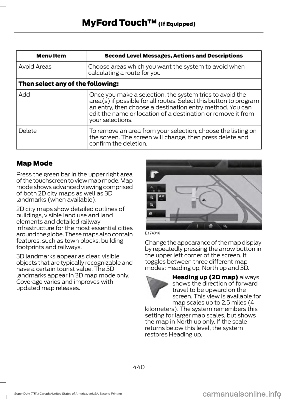
Map Mode
Press the green bar in the upper right area
of the touchscreen to view map mode. Map
mode shows advanced viewing comprised
of both 2D city maps as well as 3D
landmarks (when available).
2D city maps show detailed outlines of
buildings, visible land use and land
elements and detailed railway
infrastructure for the most essential cities
around the globe. These maps also contain
features, such as town blocks, building
footprints and railways.
3D landmarks appear as clear, visible
objects that are typically recognizable and
have a certain tourist value. The 3D
landmarks appear in 3D map mode only.
Coverage varies and improves with
updated map releases. Change the appearance of the map display
by repeatedly pressing the arrow button in
the upper left corner of the screen. It
toggles between three different map
modes: Heading up, North up and 3D.
Heading up (2D map) always
shows the direction of forward
travel to be upward on the
screen. This view is available for
map scales up to 2.5 miles (4
kilometers). The system remembers this
setting for larger map scales, but shows
the map in North up only. If the scale
returns below this level, the system
restores Heading up.
440
Super Duty (TFA) Canada/United States of America, enUSA, Second Printing MyFord Touch
™
(If Equipped)E174016 E142642
Page 506 of 510
Ordering Additional Owner's
Literature.....................................................220
Obtaining a French Owner ’s Manual...........221
Overhead Console........................................137
P
Parking Aid.......................................................177 Rear Parking Aid................................................... 177
Parking Aids
.....................................................177
Parking Brake.................................................168
Passive Anti-Theft System
.........................63
SecuriLock ™.......................................................... 63
PATS See: Passive Anti-Theft System..................... 63
Pedals................................................................68
Perchlorate.........................................................11
Phone................................................................414 Making Calls.......................................................... 417
Pairing Subsequent Cell Phones.................. 416
Pairing Your Cell Phone for the First Time.................................................................... 415
Phone Menu Options......................................... 417
Phone Settings................................................... 420
Phone Voice Commands................................. 421
Receiving Calls..................................................... 417
Text Messaging................................................... 418
Post-Crash Alert System...........................215
Power Door Locks See: Locking and Unlocking............................. 55
Power Seats
....................................................118
Power Lumbar...................................................... 118
Power Recline....................................................... 118
Power Steering Fluid Check
.....................244
Power Take-Off.............................................154
Power Windows..............................................75
Accessory Delay.................................................... 76
Bounce-Back.......................................................... 75
One-Touch Up or Down..................................... 75
Window Lock.......................................................... 76
Protecting the Environment........................14
R
Rear Axle..........................................................165
Rear Seat Armrest........................................126 Rear Seats.......................................................120
Folding the Rear Seat Back (Crew Cab)
........................................................................\
...... 120
Folding up the Rear Seat Cushion................120
Rear Under Seat Storage (Crew Cab)..........121
Returning the Seat to the Seating Position.............................................................. 120
Rear View Camera........................................178 Camera Guidelines............................................. 179
Enhanced Park Aids or Park Pilot................180
Rear Camera Delay............................................ 180
Using the Rear View Camera System.........178
Rear View Camera See: Rear View Camera.................................... 178
Recommended Towing Weights.............191 Calculating the Maximum Loaded Trailer
Weight for Your Vehicle............................... 194
Refueling..........................................................144 Fuel Filler Cap...................................................... 145
Remote Control
..............................................46
Car Finder................................................................ 47
Integrated Keyhead Transmitters .................46
Memory Feature.................................................... 47
Remote Start ......................................................... 47
Replacing the Battery......................................... 46
Sounding a Panic Alarm.................................... 47
Remote Start...................................................114 Automatic Settings............................................. 114
Removing a Headlamp..............................249
Removing the Tailgate.................................59
Repairing Minor Paint Damage...............261
Replacement Parts Recommendation.........................................11
Collision Repairs..................................................... 11
Scheduled Maintenance and Mechanical Repairs................................................................... 11
Warranty on Replacement Parts..................... 12
Replacing a Lost Key or Remote Control............................................................49
Reporting Safety Defects (Canada Only)...............................................................221
Reporting Safety Defects (U.S. Only)...............................................................221
503
Super Duty (TFA) Canada/United States of America, enUSA, Second Printing Index