service indicator FORD TAURUS 2002 4.G Owners Manual
[x] Cancel search | Manufacturer: FORD, Model Year: 2002, Model line: TAURUS, Model: FORD TAURUS 2002 4.GPages: 248, PDF Size: 2.12 MB
Page 203 of 248
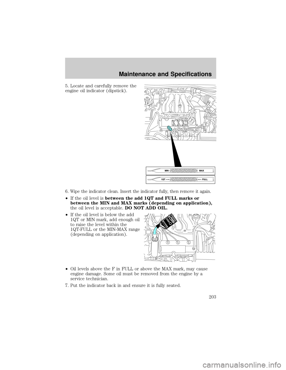
5. Locate and carefully remove the
engine oil indicator (dipstick).
6.
Wipe the indicator clean. Insert the indicator fully, then remove it again.
²If the oil level isbetween the add 1QT and FULL marks or
between the MIN and MAX marks (depending on application),
the oil level is acceptable.DO NOT ADD OIL.
²If the oil level is below the add
1QT or MIN mark, add enough oil
to raise the level within the
1QT-FULL or the MIN-MAX range
(depending on application).
²Oil levels above the F in FULL or above the MAX mark, may cause
engine damage. Some oil must be removed from the engine by a
service technician.
7. Put the indicator back in and ensure it is fully seated.
Maintenance and Specifications
203
Page 205 of 248
Ford production and aftermarket (Motorcraft) oil filters are designed for
added engine protection and long life. If a replacement oil filter is used
that does not meet Ford material and design specifications, start-up
engine noises or knock may be experienced.
It is recommended you use the appropriate Motorcraft oil filter (or
another brand meeting Ford specifications) for your engine application.
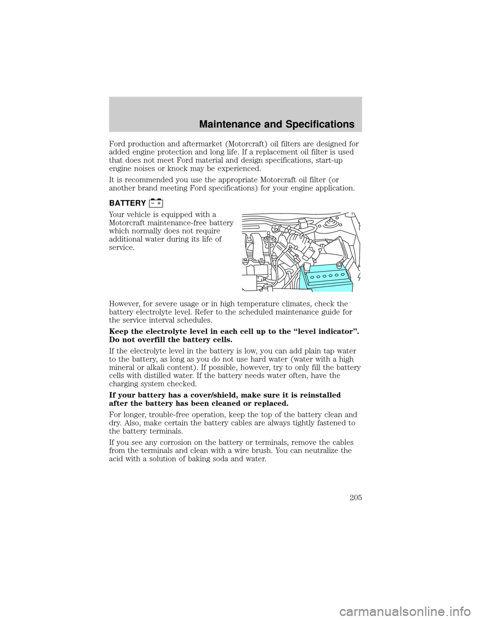
BATTERY
Your vehicle is equipped with a
Motorcraft maintenance-free battery
which normally does not require
additional water during its life of
service.
However, for severe usage or in high temperature climates, check the
battery electrolyte level. Refer to the scheduled maintenance guide for
the service interval schedules.
Keep the electrolyte level in each cell up to the ªlevel indicatorº.
Do not overfill the battery cells.
If the electrolyte level in the battery is low, you can add plain tap water
to the battery, as long as you do not use hard water (water with a high
mineral or alkali content). If possible, however, try to only fill the battery
cells with distilled water. If the battery needs water often, have the
charging system checked.
If your battery has a cover/shield, make sure it is reinstalled
after the battery has been cleaned or replaced.
For longer, trouble-free operation, keep the top of the battery clean and
dry. Also, make certain the battery cables are always tightly fastened to
the battery terminals.
If you see any corrosion on the battery or terminals, remove the cables
from the terminals and clean with a wire brush. You can neutralize the
acid with a solution of baking soda and water.
Maintenance and Specifications
205
Page 215 of 248
When refueling always shut the engine off and never allow
sparks or open flames near the filler neck. Never smoke while
refueling. Fuel vapor is extremely hazardous under certain conditions.
Care should be taken to avoid inhaling excess fumes.
The flow of fuel through a fuel pump nozzle can produce static
electricity, which can cause a fire if fuel is pumped into an
ungrounded fuel container.
Use the following guidelines to avoid static build-up when filling an
ungrounded fuel container:
²Place approved fuel container on the ground.
²DO NOT fill a fuel container while it is in the vehicle (including the
cargo area).
²Keep the fuel pump nozzle in contact with the fuel container while
filling.
²DO NOT use a device that would hold the fuel pump handle in the fill
position.
Fuel Filler Cap
Your fuel tank filler cap has an indexed design with a 1/8 turn on/off
feature.
When fueling your vehicle:
1. Turn the engine off.
2. Carefully turn the filler cap counterclockwise 1/8 of a turn until it
stops.
3. Pull to remove the cap from the fuel filler pipe.
4. To install the cap, align the tabs on the cap with the notches on the
filler pipe.
5. Turn the filler cap clockwise 1/8 of a turn until it stops.
If the ªCheck Fuel Capº
indicator comes on or if ªService Engine
Soon/Check Engineº indicator comes on and stays on when you start the
engine, the fuel filler cap may not be properly installed. Turn off the
engine, remove the fuel filler cap, align the cap properly and reinstall it.
Maintenance and Specifications
215
Page 218 of 248
FFV engine (if equipped)
Your FFV will operate well on ordinary ªRegularº unleaded gasoline, but
only the highest quality fuel ethanol will provide the same level of
protection and performance. To identify if your vehicle is an FFV, check
your VIN or the label on the inside of your fuel filler door. When
checking the VIN, look for the engine type identifier (8th character). If
your vehicle is an FFV, then the character will be labeled as a ª2.º
Standards for fuel ethanol have been developed to provide FFVs the best
possible performance, safety and durability. To assist alcohol fuel
providers in meeting these standards, guidelines have also been
developed which prescribe ªEthanol Fuel Compatibleº dispensing station
equipment. These standards and guidelines can be obtained from Ford
Motor Company. Fuel stations may apply to be certified as meeting these
standards. However, not all stations meet these standards at this time. To
ensure proper operation of your FFV on fuel ethanol, refuel at certified
stations.
If you are experiencing a rough or rolling idle after start-up with the
outside temperature above 27É C (80É F), the idle should improve within
10 to 30 seconds. If the problems persist below this temperature, see
your dealer or a qualified service technician.
Cleaner air
Ford endorses the use of reformulated ªcleaner-burningº gasolines to
improve air quality.
Running out of fuel
Avoid running out of fuel because this situation may have an adverse
affect on powertrain components.
If you have run out of fuel:
²You may need to cycle the ignition from OFF to ON several times after
refueling, to allow the fuel system to pump the fuel from the tank to
the engine.
²
Theindicator may come on. For more information on the ªService
Engine Soonº indicator, refer to theInstrument Clusterchapter.
Fuel Filter
For fuel filter replacement, see your dealer or a qualified service
technician. Refer to the scheduled maintenance guide for the appropriate
intervals for changing the fuel filter.
Maintenance and Specifications
218
Page 223 of 248
Do not park, idle, or drive your vehicle in dry grass or other dry
ground cover. The emission system heats up the engine
compartment and exhaust system, which can start a fire.
Illumination of the
indicator, charging system warning light or the
temperature warning light, fluid leaks, strange odors, smoke or loss of
engine power, could indicate that the emission control system is not
working properly.
Exhaust leaks may result in entry of harmful and potentially
lethal fumes into the passenger compartment.
Do not make any unauthorized changes to your vehicle or engine. By law,
vehicle owners and anyone who manufactures, repairs, services, sells, leases,
trades vehicles, or supervises a fleet of vehicles are not permitted to
intentionally remove an emission control device or prevent it from working.
Information about your vehicle's emission system is on the Vehicle Emission
Control Information Decal located on or near the engine. This decal
identifies engine displacement and gives some tune up specifications.
Please consult your ªWarranty Guideº for complete emission warranty
information.
Readiness for Inspection/Maintenance (I/M) testing
In some localities, it may be a legal requirement to pass an I/M test of
the on-board diagnostics system. If your
indicator is on, refer to the
description in theWarning lights and chimessection of the
Instrument Clusterchapter. Your vehicle may not pass the I/M test with
the
indicator on.
If the vehicle's powertrain system or its battery has just been serviced,
the on-board diagnostics system is reset to a ªnot ready for I/M testº
condition. To ready the on-board diagnostics system for I/M testing, a
minimum of 30 minutes of city and highway driving is necessary as
described below:
²First, at least 10 minutes of driving on an expressway or highway.
²Next, at least 20 minutes driving in stop-and-go, city-type traffic with
at least four idle periods.
Allow the vehicle to sit for at least eight hours without starting the
engine. Then, start the engine and complete the above driving cycle. The
engine must warm up to its normal operating temperature. Once started,
do not turn off the engine until the above driving cycle is complete.
Maintenance and Specifications
223
Page 224 of 248
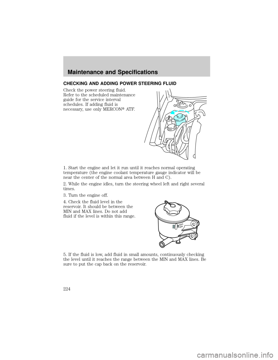
CHECKING AND ADDING POWER STEERING FLUID
Check the power steering fluid.
Refer to the scheduled maintenance
guide for the service interval
schedules. If adding fluid is
necessary, use only MERCONtAT F.
1. Start the engine and let it run until it reaches normal operating
temperature (the engine coolant temperature gauge indicator will be
near the center of the normal area between H and C).
2. While the engine idles, turn the steering wheel left and right several
times.
3. Turn the engine off.
4. Check the fluid level in the
reservoir. It should be between the
MIN and MAX lines. Do not add
fluid if the level is within this range.
5. If the fluid is low, add fluid in small amounts, continuously checking
the level until it reaches the range between the MIN and MAX lines. Be
sure to put the cap back on the reservoir.
MINMAX
Maintenance and Specifications
224
Page 246 of 248

high beam ...........................14, 52
replacing bulbs .........................58
turning on and off ....................51
warning chime ..........................15
Heating ........................................43
heating and air conditioning
system .......................................40
Hood ..........................................198
I
Ignition ...............................138, 236
Infant seats
(see Safety seats) .....................130
Inspection/maintenance
(I/M) testing ..............................223
Instrument panel
cleaning ...................................193
cluster ................................10, 193
lighting up panel
and interior ...............................52
J
Jack ............................................168
positioning ...............................168
storage .....................................168
Jump-starting your vehicle ......172
K
Keyless entry system .................91
autolock .....................................94
keypad .......................................91
locking and unlocking doors ....93
programming entry code .........92
Keys .................................94±95, 97
key in ignition chime ...............15
positions of the ignition .........138L
Lamps
autolamp system .......................51
bulb replacement
specifications chart ..................56
cargo lamps ...............................52
daytime running light ...............51
headlamps .................................51
headlamps, flash to pass ..........52
instrument panel, dimming .....52
interior lamps .....................54, 56
replacing
bulbs ..................56, 58, 60±62, 64
Lane change indicator
(see Turn signal) ........................54
Liftgate ..................................81, 88
Lights, warning and indicator ....10
air bag ........................................12
anti-lock brakes (ABS) ....12, 144
anti-theft ...................................14
brake ..........................................12
charging system ........................12
check coolant ............................14
cruise indicator .........................13
door ajar ....................................14
fuel cap light .............................11
high beam .................................14
low coolant ................................13
low fuel ......................................13
oil pressure ...............................13
safety belt .................................12
service engine soon ..................10
speed control ............................78
traction control active ..............13
turn signal indicator .................14
Load limits .................................153
GAWR ......................................153
GVWR ......................................153
trailer towing ..........................153
Index
246