sensor FORD TAURUS 2003 4.G Owners Manual
[x] Cancel search | Manufacturer: FORD, Model Year: 2003, Model line: TAURUS, Model: FORD TAURUS 2003 4.GPages: 216, PDF Size: 10.87 MB
Page 49 of 216
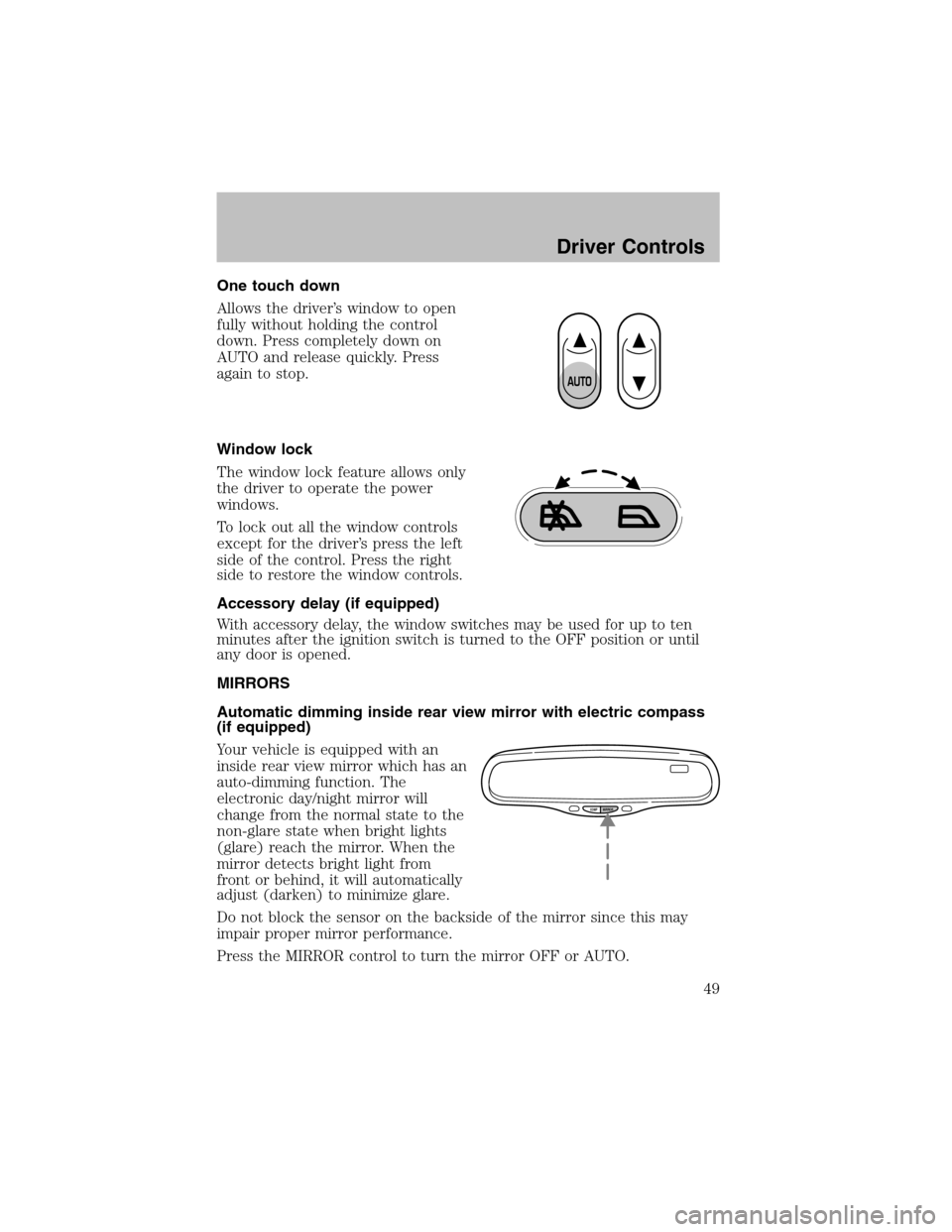
One touch down
Allows the driver’s window to open
fully without holding the control
down. Press completely down on
AUTO and release quickly. Press
again to stop.
Window lock
The window lock feature allows only
the driver to operate the power
windows.
To lock out all the window controls
except for the driver’s press the left
side of the control. Press the right
side to restore the window controls.
Accessory delay (if equipped)
With accessory delay, the window switches may be used for up to ten
minutes after the ignition switch is turned to the OFF position or until
any door is opened.
MIRRORS
Automatic dimming inside rear view mirror with electric compass
(if equipped)
Your vehicle is equipped with an
inside rear view mirror which has an
auto-dimming function. The
electronic day/night mirror will
change from the normal state to the
non-glare state when bright lights
(glare) reach the mirror. When the
mirror detects bright light from
front or behind, it will automatically
adjust (darken) to minimize glare.
Do not block the sensor on the backside of the mirror since this may
impair proper mirror performance.
Press the MIRROR control to turn the mirror OFF or AUTO.
COMP MIRROR
Driver Controls
49
Page 79 of 216

To close the seat, make sure the safety belts are properly stowed, then
lift the remote latch release and push the seat down until it latches. Pull
up on the handle and push the floor panel into place.
SAFETY RESTRAINTS
Personal Safety System
The Personal Safety System provides an improved overall level of frontal
crash protection to front seat occupants and is designed to help further
reduce the risk of air bag-related injuries. The system is able to analyze
different occupant conditions and crash severity before activating the
appropriate safety devices to help better protect a range of occupants in
a variety of frontal crash situations.
Your vehicle’s Personal Safety System consists of:
•Driver and passenger dual-stage air bag supplemental restraints.
•Front safety belts with pretensioners, energy management retractors,
and safety belt usage sensors.
•Driver’s seat position sensor.
•Front crash severity sensor.
•Restraints Control Module (RCM) with impact and safing sensors.
•Restraint system warning light and back-up tone.
•The electrical wiring for the air bags, crash sensor(s), safety belt
pretensioners, front safety belt usage sensors, driver seat position
sensor, and indicator lights.
How does the personal safety system work?
The Personal Safety System can adapt the deployment strategy of your
vehicle’s safety devices according to crash severity and occupant
conditions. A collection of crash and occupant sensors provides
information to the Restraints Control Module (RCM). During a crash, the
RCM activates the safety belt pretensioners and/or either one or both
stages of the dual-stage air bag supplemental restraints based on crash
severity and occupant conditions.
The fact that the pretensioners or air bags did not activate for both front
seat occupants in a collision does not mean that something is wrong with
the system. Rather, it means the Personal Safety System determined the
accident conditions (crash severity, belt usage, etc.) were not
appropriate to activate these safety devices. Front air bags and
pretensioners are designed to activate only in frontal and near-frontal
Seating and Safety Restraints
79
Page 80 of 216

collisions, not rollovers, side-impacts, or rear-impacts unless the collision
causes sufficient longitudinal deceleration.
Driver and passenger dual-stage air bag supplemental restraints
The dual-stage air bags offer the capability to tailor the level of air bag
inflation energy. A lower, less forceful energy level is provided for more
common, moderate-severity impacts. A higher energy level is used for
the most severe impacts. Refer toAir bag Supplemental Restraints
section in this chapter.
Front crash severity sensor
The front crash severity sensor enhances the ability to detect the
severity of an impact. Positioned up front, it provides valuable
information early in the crash event on the severity of the impact. This
allows your Personal Safety System to distinguish between different
levels of crash severity and modify the deployment strategy of the
dual-stage air bags and safety belt pretensioners.
Driver’s seat position sensor
The driver’s seat position sensor allows your Personal Safety System to
tailor the deployment level of the driver dual-stage air bag based on seat
position. The system is designed to help protect smaller drivers sitting
close to the driver air bag by providing a lower air bag output level.
Front safety belt usage sensors
The front safety belt usage sensors detect whether or not the driver and
front outboard passenger safety belts are fastened. This information
allows your Personal Safety System to tailor the air bag deployment and
safety belt pretensioner activation depending upon safety belt usage.
Refer toSafety Beltsection in this chapter.
Front safety belt pretensioners
The safety belt pretensioners are designed to tighten the safety belts
firmly against the occupant’s body during a collision. This maximizes the
effectiveness of the safety belts and helps properly position the occupant
relative to the air bag to improve protection. The safety belt
pretensioners can be either activated alone or, if the collision is of
sufficient severity, together with the air bags.
Seating and Safety Restraints
80
Page 81 of 216
Front safety belt energy management retractors
The front safety belt energy management retractors allow webbing to be
pulled out of the retractor in a gradual and controlled manner in
response to the occupant’s forward momentum. This helps reduce the
risk of force-related injuries to the occupant’s chest by limiting the load
on the occupant. Refer toSafety Beltsection in this chapter.
Determining if the Personal Safety System is operational
The Personal Safety System uses a warning light in the instrument
cluster or a back-up tone to indicate the condition of the system. Refer
to theWarning Lightsection in theInstrument Clusterchapter.
Routine maintenance of the Personal Safety System is not required.
The Restraints Control Module (RCM) monitors its own internal circuits
and the circuits for the air bag supplemental restraints, crash sensor(s),
safety belt pretensioners, front safety belt buckle sensors, and the driver
seat position sensor. In addition, the RCM also monitors the restraints
warning light in the instrument cluster. A difficulty with the system is
indicated by one or more of the following.
•The warning light will either flash or stay lit.
•The warning light will not illuminate immediately after ignition is
turned on.
•A series of five beeps will be heard. The tone pattern will repeat
periodically until the problem and warning light are repaired.
If any of these things happen, even intermittently, have the Personal
Safety System serviced at your dealership or by a qualified technician
immediately. Unless serviced, the system may not function properly in
the event of a collision.
Safety belt precautions
Always drive and ride with your seatback upright and the lap
belt snug and low across the hips.
To reduce the risk of injury, make sure children sit where they
can be properly restrained.
Never let a passenger hold a child on his or her lap while the
vehicle is moving. The passenger cannot protect the child from
injury in a collision.
Seating and Safety Restraints
81
Page 86 of 216
Safety belt usage sensors
The driver and front outboard passenger safety belt buckles are
equipped with sensors that detect if the safety belts are fastened. The
sensors provide information to the Personal Safety System which can
then adapt the air bag deployment or safety belt pretensioner activation
based upon safety belt usage.
The Personal Safety System provides the most benefit to belted
occupants. The system monitors and tailors the air bag
deployment based upon safety belt usage. Failure to properly wear
your safety belt will increase your risk of injury.
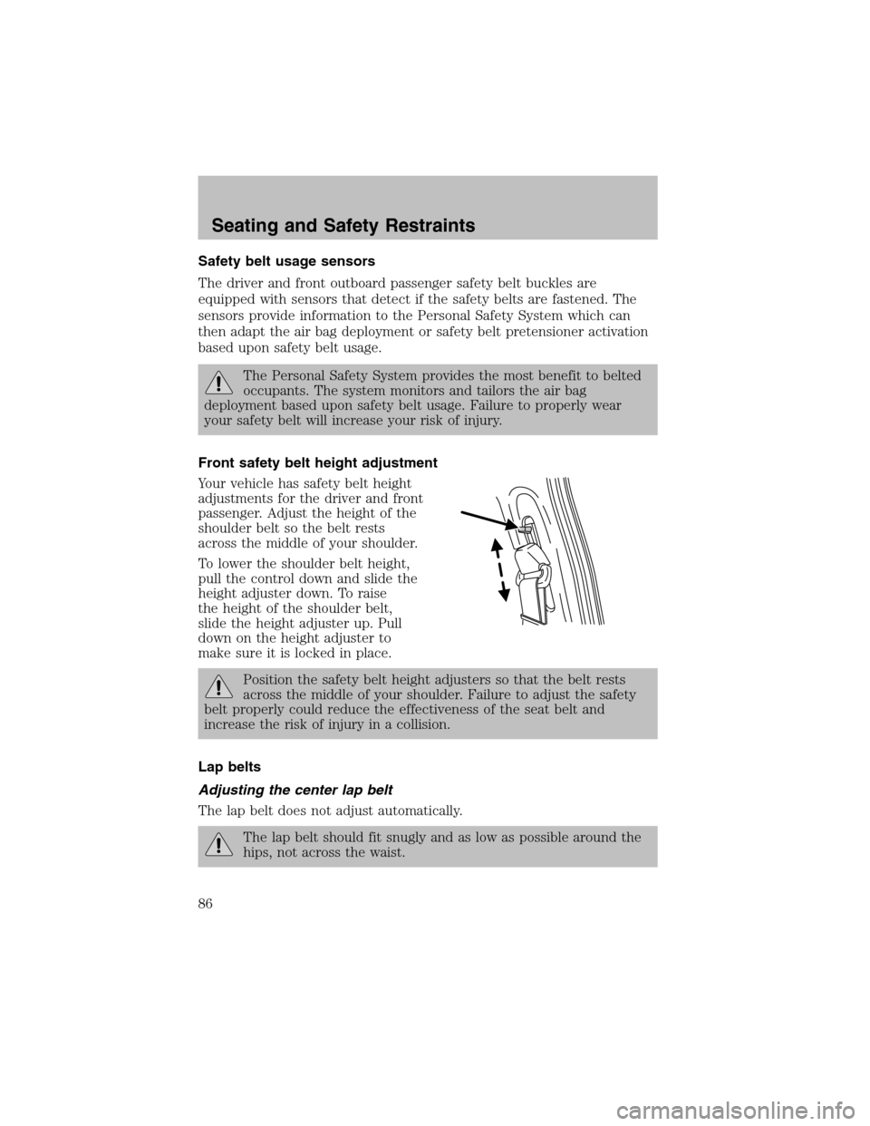
Front safety belt height adjustment
Your vehicle has safety belt height
adjustments for the driver and front
passenger. Adjust the height of the
shoulder belt so the belt rests
across the middle of your shoulder.
To lower the shoulder belt height,
pull the control down and slide the
height adjuster down. To raise
the height of the shoulder belt,
slide the height adjuster up. Pull
down on the height adjuster to
make sure it is locked in place.
Position the safety belt height adjusters so that the belt rests
across the middle of your shoulder. Failure to adjust the safety
belt properly could reduce the effectiveness of the seat belt and
increase the risk of injury in a collision.
Lap belts
Adjusting the center lap belt
The lap belt does not adjust automatically.
The lap belt should fit snugly and as low as possible around the
hips, not across the waist.
Seating and Safety Restraints
86
Page 94 of 216
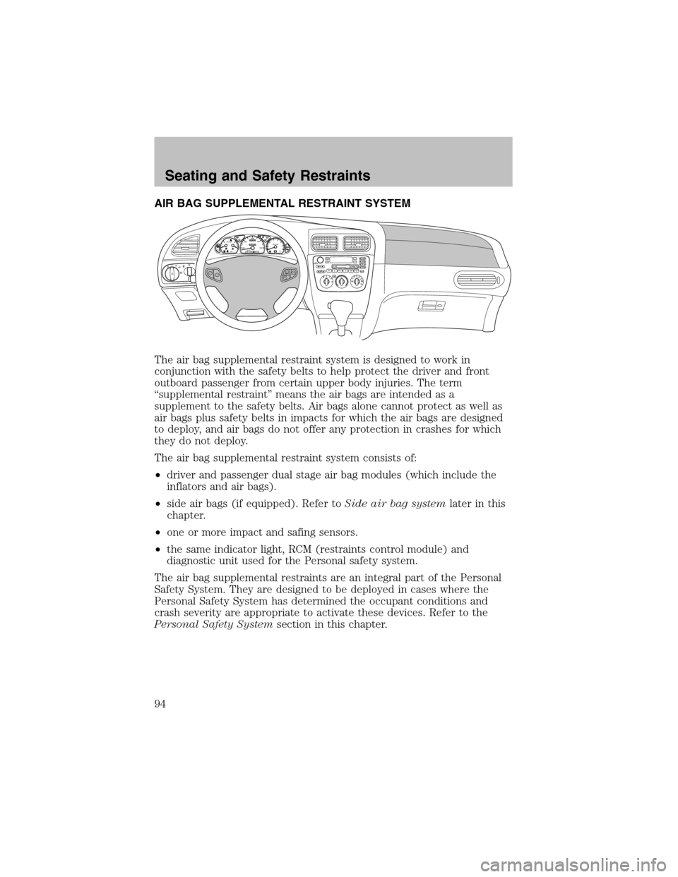
AIR BAG SUPPLEMENTAL RESTRAINT SYSTEM
The air bag supplemental restraint system is designed to work in
conjunction with the safety belts to help protect the driver and front
outboard passenger from certain upper body injuries. The term
“supplemental restraint”means the air bags are intended as a
supplement to the safety belts. Air bags alone cannot protect as well as
air bags plus safety belts in impacts for which the air bags are designed
to deploy, and air bags do not offer any protection in crashes for which
they do not deploy.
The air bag supplemental restraint system consists of:
•driver and passenger dual stage air bag modules (which include the
inflators and air bags).
•side air bags (if equipped). Refer toSide air bag systemlater in this
chapter.
•one or more impact and safing sensors.
•the same indicator light, RCM (restraints control module) and
diagnostic unit used for the Personal safety system.
The air bag supplemental restraints are an integral part of the Personal
Safety System. They are designed to be deployed in cases where the
Personal Safety System has determined the occupant conditions and
crash severity are appropriate to activate these devices. Refer to the
Personal Safety Systemsection in this chapter.
AVOL
PUSH ONAM
FM H
M
EJ TAPEBASS
TREB
BAL
FADE
SCAN REW
FF
RCOMP
OFF
A/C
MAX
A/CSHUFFLE
SIDE 1-2CD SEEK
TUNE
DISC 1-61 234 56
P!
BRAKE
+ –
CRUISERPMx1000ABS0 123
4
5
6
72060
14 0
18 0 10 0km/hP R N D 2 10000000000EFC HFUEL DOOR >THEFTLOW
COOLANT
ONSET+RESCST-OFF
Seating and Safety Restraints
94
Page 99 of 216
All occupants of the vehicle should always wear their safety belts
even when an air bag SRS is provided.
How does the side air bag system work?
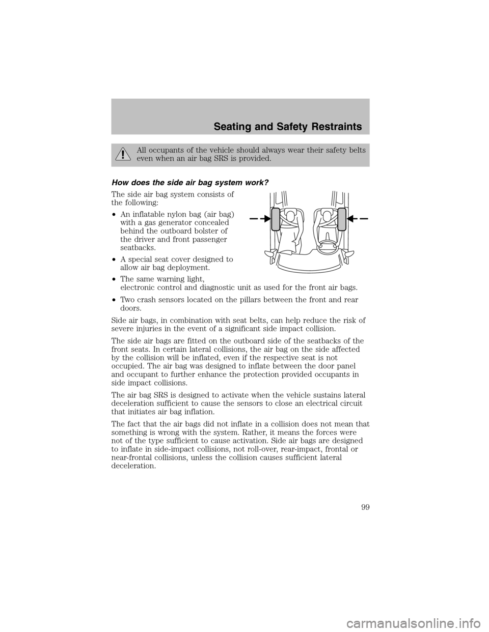
The side air bag system consists of
the following:
•An inflatable nylon bag (air bag)
with a gas generator concealed
behind the outboard bolster of
the driver and front passenger
seatbacks.
•A special seat cover designed to
allow air bag deployment.
•The same warning light,
electronic control and diagnostic unit as used for the front air bags.
•Two crash sensors located on the pillars between the front and rear
doors.
Side air bags, in combination with seat belts, can help reduce the risk of
severe injuries in the event of a significant side impact collision.
The side air bags are fitted on the outboard side of the seatbacks of the
front seats. In certain lateral collisions, the air bag on the side affected
by the collision will be inflated, even if the respective seat is not
occupied. The air bag was designed to inflate between the door panel
and occupant to further enhance the protection provided occupants in
side impact collisions.
The air bag SRS is designed to activate when the vehicle sustains lateral
deceleration sufficient to cause the sensors to close an electrical circuit
that initiates air bag inflation.
The fact that the air bags did not inflate in a collision does not mean that
something is wrong with the system. Rather, it means the forces were
not of the type sufficient to cause activation. Side air bags are designed
to inflate in side-impact collisions, not roll-over, rear-impact, frontal or
near-frontal collisions, unless the collision causes sufficient lateral
deceleration.
Seating and Safety Restraints
99
Page 138 of 216
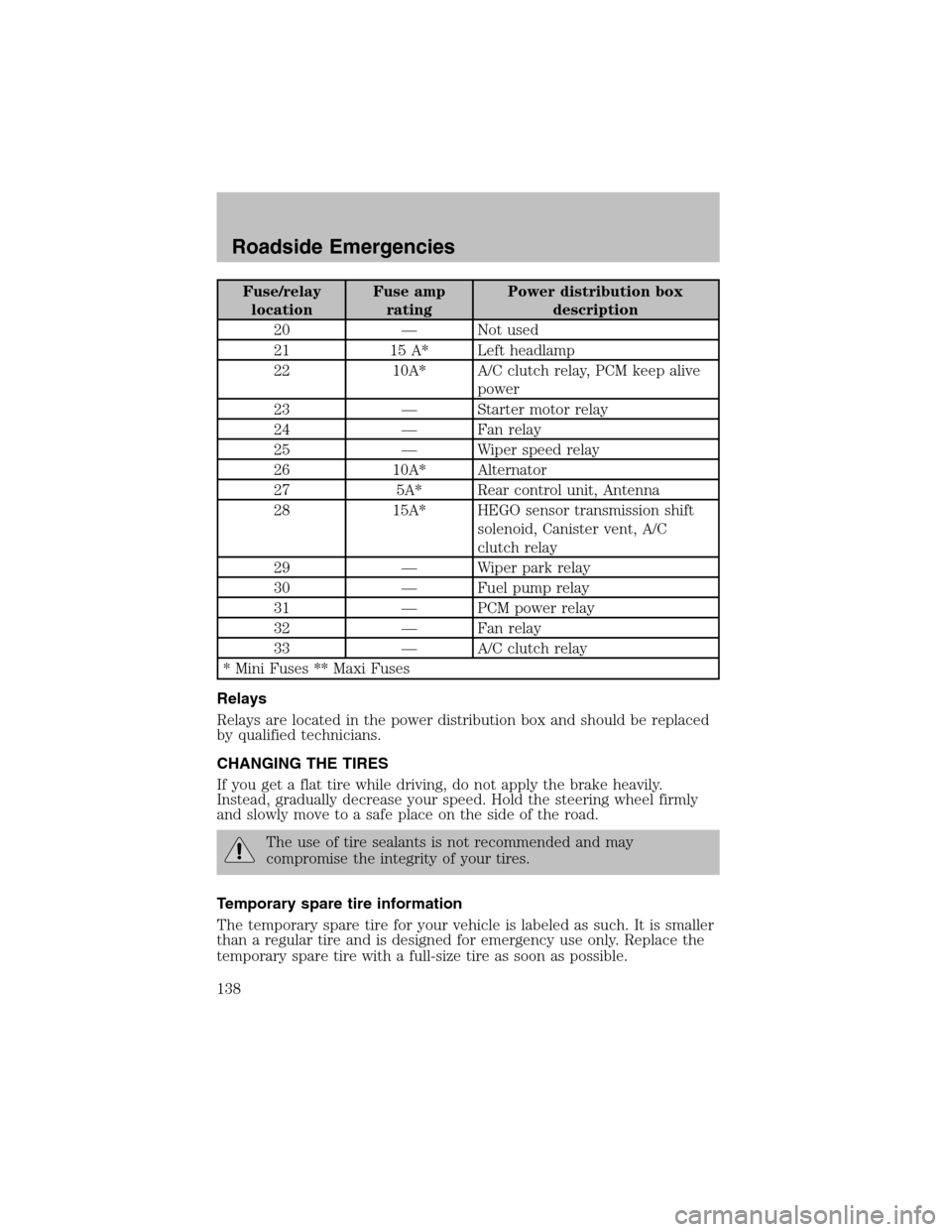
Fuse/relay
locationFuse amp
ratingPower distribution box
description
20—Not used
21 15 A* Left headlamp
22 10A* A/C clutch relay, PCM keep alive
power
23—Starter motor relay
24—Fan relay
25—Wiper speed relay
26 10A* Alternator
27 5A* Rear control unit, Antenna
28 15A* HEGO sensor transmission shift
solenoid, Canister vent, A/C
clutch relay
29—Wiper park relay
30—Fuel pump relay
31—PCM power relay
32—Fan relay
33—A/C clutch relay
* Mini Fuses ** Maxi Fuses
Relays
Relays are located in the power distribution box and should be replaced
by qualified technicians.
CHANGING THE TIRES
If you get a flat tire while driving, do not apply the brake heavily.
Instead, gradually decrease your speed. Hold the steering wheel firmly
and slowly move to a safe place on the side of the road.
The use of tire sealants is not recommended and may
compromise the integrity of your tires.
Temporary spare tire information
The temporary spare tire for your vehicle is labeled as such. It is smaller
than a regular tire and is designed for emergency use only. Replace the
temporary spare tire with a full-size tire as soon as possible.
Roadside Emergencies
138