wheel FORD TAURUS 2005 4.G Owners Manual
[x] Cancel search | Manufacturer: FORD, Model Year: 2005, Model line: TAURUS, Model: FORD TAURUS 2005 4.GPages: 248, PDF Size: 2.66 MB
Page 1 of 248
Introduction 4
Instrument Cluster 10
Warning and control lights 10
Gauges 13
Entertainment Systems 15
AM/FM stereo 15
AM/FM stereo cassette 16
AM/FM stereo with CD 19
CD changer 21
Climate Controls 24
Manual heating and air conditioning 24
Electronic automatic temperature control 26
Rear window defroster 28
Lights 30
Headlamps 30
Turn signal control 33
Bulb replacement 35
Driver Controls 46
Windshield wiper/washer control 46
Steering wheel adjustment 47
Power windows 48
Mirrors 50
Speed control 51
Message center 58
Locks and Security 73
Keys 73
Locks 73
Anti-theft system 83
Table of Contents
1
Table of Contents
Page 6 of 248

SPECIAL NOTICES
Emission warranty
The New Vehicle Limited Warranty includes Bumper-to-Bumper
Coverage, Safety Restraint Coverage, Corrosion Coverage, and 6.0L
Power Stroke Diesel Engine Coverage. In addition, your vehicle is eligible
for Emissions Defect and Emissions Performance Warranties. For a
detailed description of what is covered and what is not covered, refer to
theWarranty Guidethat is provided to you along with your Owner's
Guide.
Service Data Recording
Service data recorders in your vehicle are capable of collecting and
storing diagnostic information about your vehicle. This potentially
includes information about the performance or status of various systems
and modules in the vehicle, such as engine, throttle, steering or brake
systems. In order to properly diagnose and service your vehicle, Ford
Motor Company, Ford of Canada, and service and repair facilities may
access vehicle diagnostic information through a direct connection to your
vehicle when diagnosing or servicing your vehicle.
Event Data Recording
Other modules in your vehicle Ð event data recorders Ð are capable of
collecting and storing data during a crash or near crash event. The
recorded information may assist in the investigation of such an event.
The modules may record information about both the vehicle and the
occupants, potentially including information such as:
²how various systems in your vehicle were operating;
²whether or not the driver and passenger seatbelts were buckled;
²how far (if at all) the driver was depressing the accelerator and/or the
brake pedal;
²how fast the vehicle was traveling; and
²where the driver was positioning the steering wheel.
To access this information, special equipment must be directly connected
to the recording modules. Ford Motor Company and Ford of Canada do
not access event data recorder information without obtaining consent,
unless pursuant to court order or where required by law enforcement,
other government authorities or other third parties acting with lawful
authority. Other parties may seek to access the information
independently of Ford Motor Company and Ford of Canada.
Introduction
6
Page 47 of 248
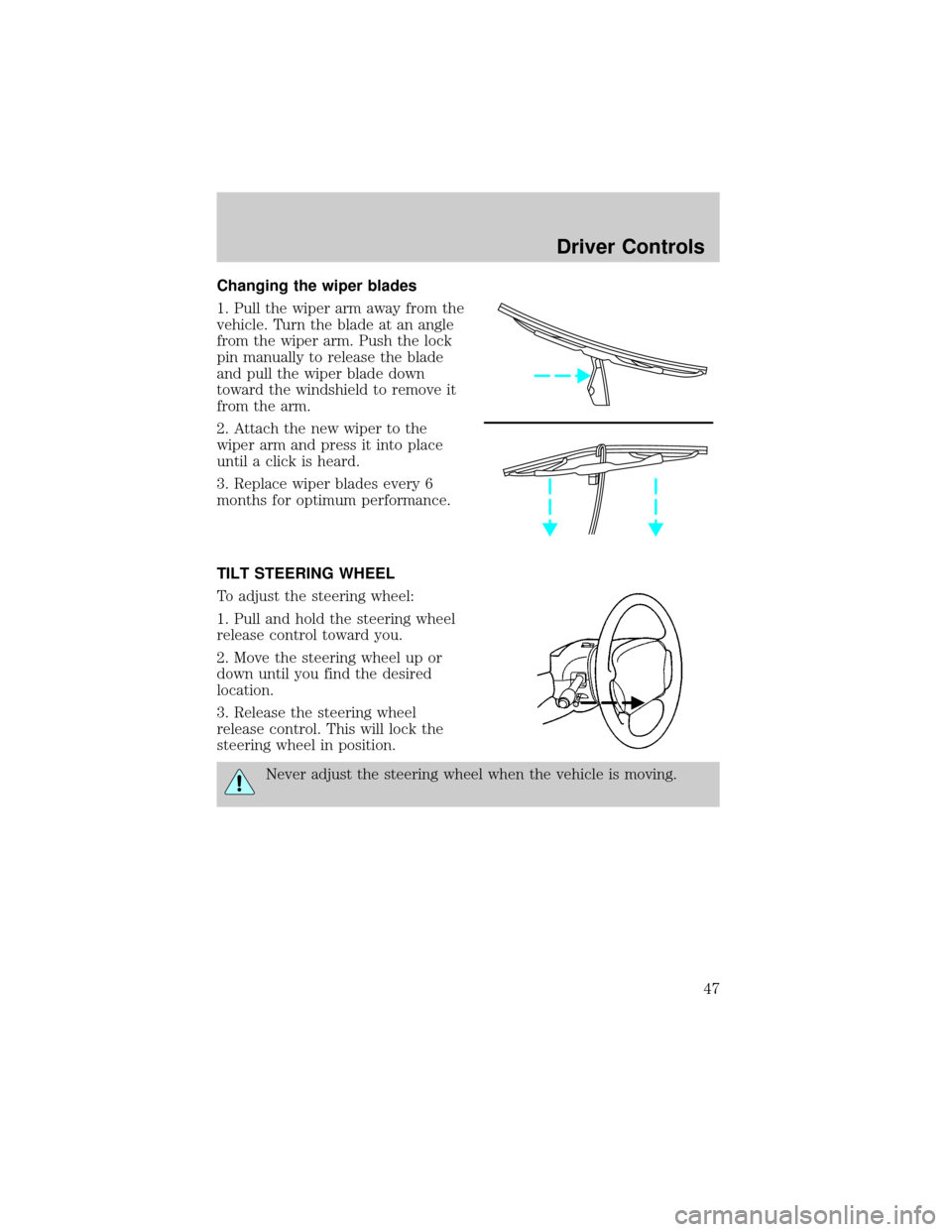
Changing the wiper blades
1. Pull the wiper arm away from the
vehicle. Turn the blade at an angle
from the wiper arm. Push the lock
pin manually to release the blade
and pull the wiper blade down
toward the windshield to remove it
from the arm.
2. Attach the new wiper to the
wiper arm and press it into place
until a click is heard.
3. Replace wiper blades every 6
months for optimum performance.
TILT STEERING WHEEL
To adjust the steering wheel:
1. Pull and hold the steering wheel
release control toward you.
2. Move the steering wheel up or
down until you find the desired
location.
3. Release the steering wheel
release control. This will lock the
steering wheel in position.
Never adjust the steering wheel when the vehicle is moving.
Driver Controls
47
Page 52 of 248
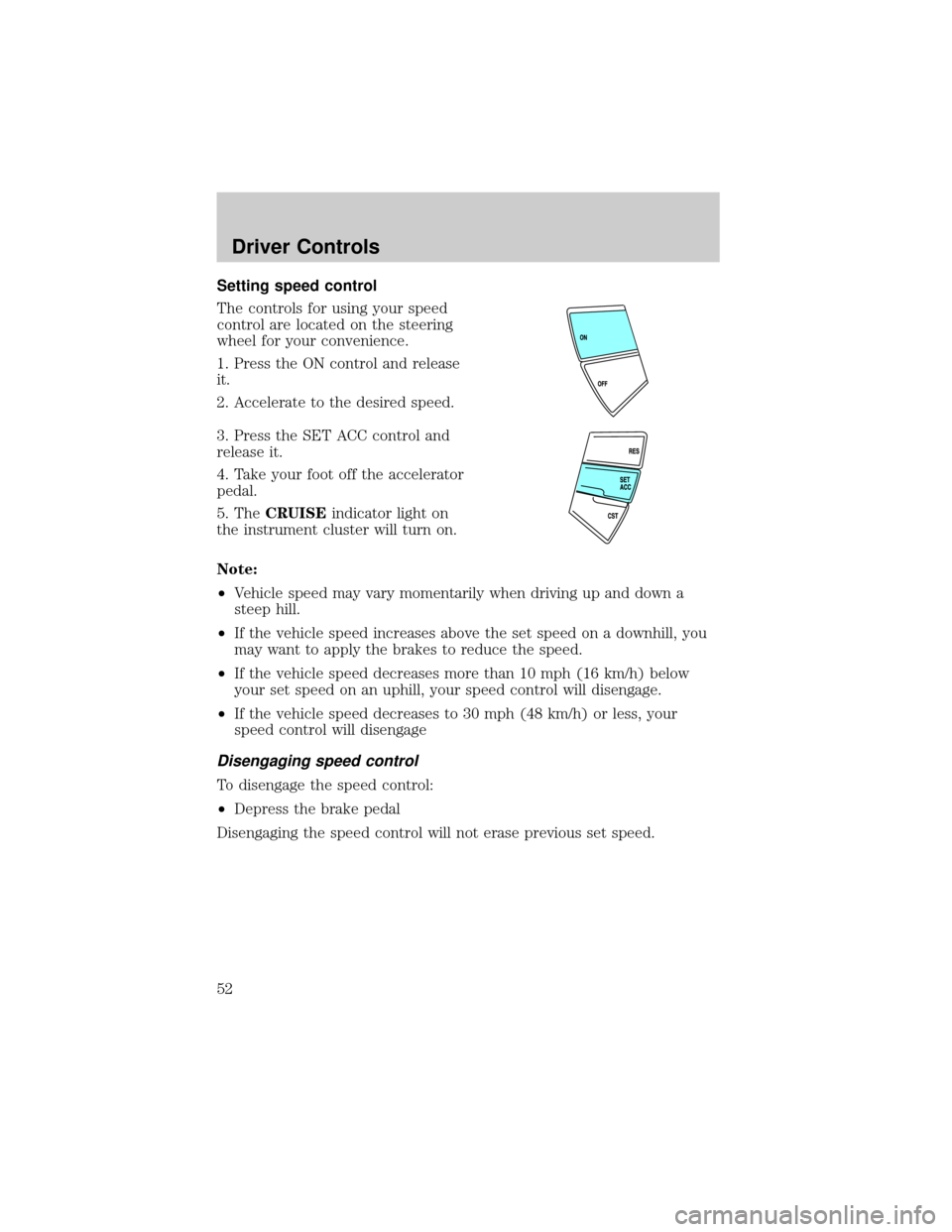
Setting speed control
The controls for using your speed
control are located on the steering
wheel for your convenience.
1. Press the ON control and release
it.
2. Accelerate to the desired speed.
3. Press the SET ACC control and
release it.
4. Take your foot off the accelerator
pedal.
5. TheCRUISEindicator light on
the instrument cluster will turn on.
Note:
²Vehicle speed may vary momentarily when driving up and down a
steep hill.
²If the vehicle speed increases above the set speed on a downhill, you
may want to apply the brakes to reduce the speed.
²If the vehicle speed decreases more than 10 mph (16 km/h) below
your set speed on an uphill, your speed control will disengage.
²If the vehicle speed decreases to 30 mph (48 km/h) or less, your
speed control will disengage
Disengaging speed control
To disengage the speed control:
²Depress the brake pedal
Disengaging the speed control will not erase previous set speed.
Driver Controls
52
Page 69 of 248
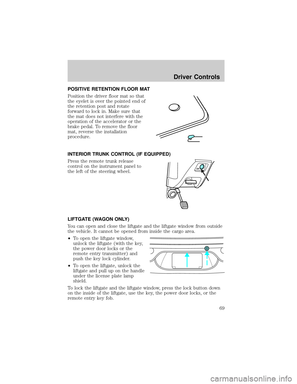
POSITIVE RETENTION FLOOR MAT
Position the driver floor mat so that
the eyelet is over the pointed end of
the retention post and rotate
forward to lock in. Make sure that
the mat does not interfere with the
operation of the accelerator or the
brake pedal. To remove the floor
mat, reverse the installation
procedure.
INTERIOR TRUNK CONTROL (IF EQUIPPED)
Press the remote trunk release
control on the instrument panel to
the left of the steering wheel.
LIFTGATE (WAGON ONLY)
You can open and close the liftgate and the liftgate window from outside
the vehicle. It cannot be opened from inside the cargo area.
²To open the liftgate window,
unlock the liftgate (with the key,
the power door locks or the
remote entry transmitter) and
push the key lock cylinder.
²To open the liftgate, unlock the
liftgate and pull up on the handle
under the license plate lamp
shield.
To lock the liftgate and the liftgate window, press the lock button down
on the inside of the liftgate, use the key, the power door locks, or the
remote entry key fob.
Driver Controls
69
Page 72 of 248
The cover may cause injury in a sudden stop or accident if it is
not securely installed.
Cargo utility hooks (Sedan)
The utility hooks located inside the trunk can be used to attach a cargo
net to secure lightweight objects or hang small items on. Do not hang
more than 12 kg (20 lbs) on the hooks.
The hooks are not designed to restrain objects during a collision.
LUGGAGE RACK (IF EQUIPPED)
The rear cross-bar can be adjusted to fit the item being carried. The
front cross-bar does not move. Do not load more than 44 kg (100 lbs.)
on the luggage rack.
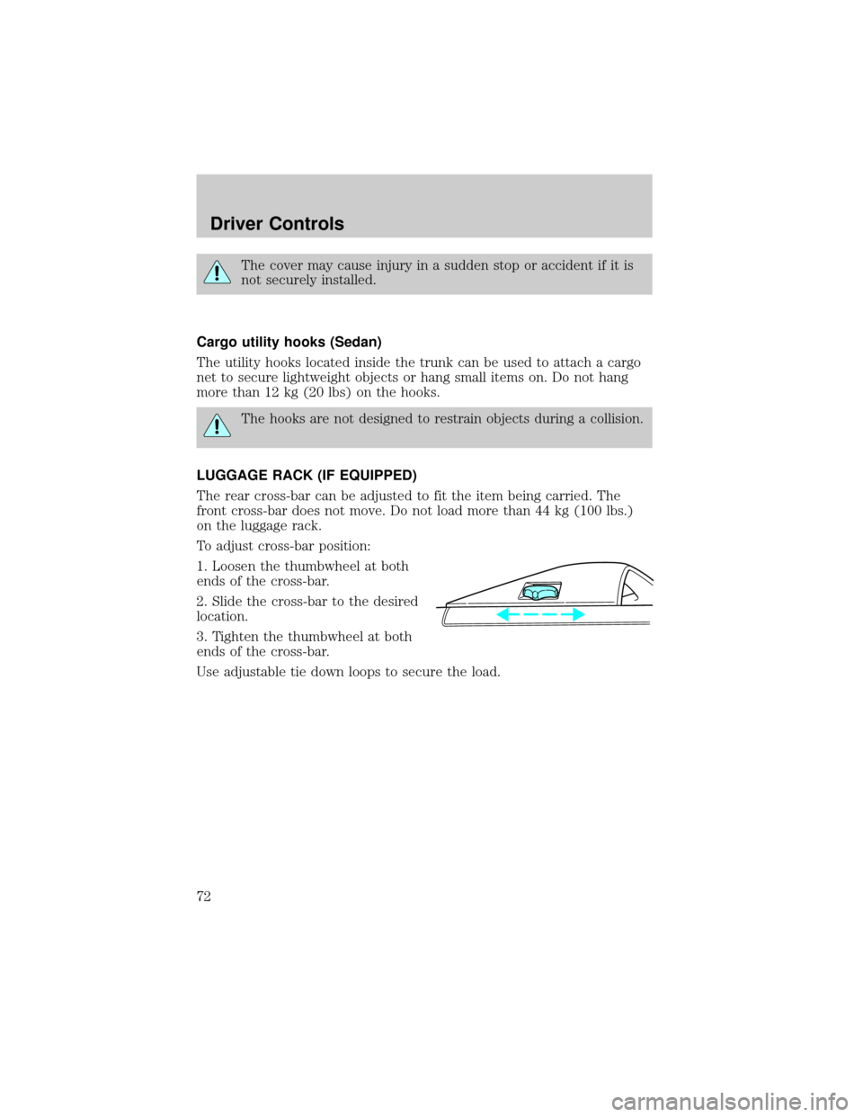
To adjust cross-bar position:
1. Loosen the thumbwheel at both
ends of the cross-bar.
2. Slide the cross-bar to the desired
location.
3. Tighten the thumbwheel at both
ends of the cross-bar.
Use adjustable tie down loops to secure the load.
Driver Controls
72
Page 130 of 248
STARTING
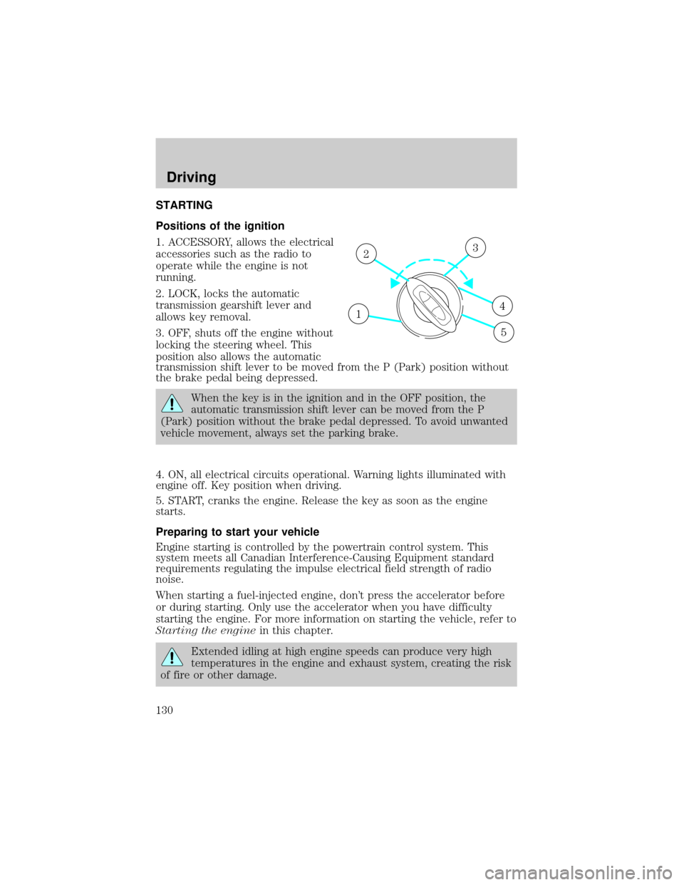
Positions of the ignition
1. ACCESSORY, allows the electrical
accessories such as the radio to
operate while the engine is not
running.
2. LOCK, locks the automatic
transmission gearshift lever and
allows key removal.
3. OFF, shuts off the engine without
locking the steering wheel. This
position also allows the automatic
transmission shift lever to be moved from the P (Park) position without
the brake pedal being depressed.
When the key is in the ignition and in the OFF position, the
automatic transmission shift lever can be moved from the P
(Park) position without the brake pedal depressed. To avoid unwanted
vehicle movement, always set the parking brake.
4. ON, all electrical circuits operational. Warning lights illuminated with
engine off. Key position when driving.
5. START, cranks the engine. Release the key as soon as the engine
starts.
Preparing to start your vehicle
Engine starting is controlled by the powertrain control system. This
system meets all Canadian Interference-Causing Equipment standard
requirements regulating the impulse electrical field strength of radio
noise.
When starting a fuel-injected engine, don't press the accelerator before
or during starting. Only use the accelerator when you have difficulty
starting the engine. For more information on starting the vehicle, refer to
Starting the enginein this chapter.
Extended idling at high engine speeds can produce very high
temperatures in the engine and exhaust system, creating the risk
of fire or other damage.
1
23
4
5
Driving
Driving
130
Page 134 of 248
strongly recommended if you live in a region where temperatures reach
-10ÉF (-23ÉC) or below. For best results, plug the heater in at least three
hours before starting the vehicle. The heater can be plugged in the night
before starting the vehicle.
To reduce the risk of electrical shock, do not use your heater
with ungrounded electrical systems or two-pronged (cheater)
adapters.
Guarding against exhaust fumes
Carbon monoxide is present in exhaust fumes. Take precautions to avoid
its dangerous effects.
If you smell exhaust fumes inside your vehicle, have your dealer
inspect your vehicle immediately. Do not drive if you smell
exhaust fumes.
Important ventilating information
If the engine is idling while the vehicle is stopped for a long period of
time, open the windows at least one inch (2.5 cm) or adjust the heating
or air conditioning to bring in fresh air.
BRAKES
Your service brakes are self-adjusting. Refer to the Scheduled
Maintenance Guide for maintenance recommendations.
Occasional brake noise is normal and often does not indicate a
performance concern with the vehicle's brake system. In normal
operation, automotive brake systems may emit occasional or intermittent
squeal or groan noises when the brakes are applied. Such noises are
usually heard during the first few brake applications in the morning;
however, they may be heard at any time while braking and can be
aggravated by environmental conditions such as cold, heat, moisture,
road dust, salt or mud. If a ªmetal-to-metal,º ªcontinuous grindingº or
ªcontinuous squealº sound is present while braking, the brake linings
may be worn-out and should be inspected by a qualified service
technician.
If the vehicle has continuous vibration or shudder in the steering wheel
while braking, the vehicle should be inspected by a qualified service
technician.
Driving
134
Page 135 of 248

Refer toBrake system warning
lightin theInstrument Cluster
chapter for information on the brake
system warning light.
Four-wheel anti-lock brake system (ABS) (if equipped)
On vehicles equipped with an anti-lock braking system (ABS), a noise
from the hydraulic pump motor and pulsation in the pedal may be
observed during ABS braking events. Pedal pulsation coupled with noise
while braking under panic conditions or on loose gravel, bumps, wet or
snowy roads is normal and indicates proper functioning of the vehicle's
anti-lock brake system. The ABS performs a self-check after you start
the engine and begin to drive away. A brief mechanical noise may be
heard during this test. This is normal. If a malfunction is found, the ABS
warning light will come on.
The ABS operates by detecting the onset of wheel lockup during brake
applications and compensates for this tendency. The wheels are
prevented from locking even when the brakes are firmly applied.
Using ABS
²In an emergency or when maximum efficiency from the four-wheel
ABS is required, apply continuous force on the brake. The four wheel
ABS will be activated immediately, thus allowing you to retain steering
control of your vehicle and, providing there is sufficient space, will
enable you to avoid obstacles and bring the vehicle to a controlled
stop.
²The anti-lock system does not reduce stopping distance. Always leave
enough room between your vehicle and the vehicle in front of you to
stop.
²We recommend that you familiarize yourself with this braking
technique. However, avoid taking any unnecessary risks.
ABS warning lamp
The ABS lamp in the instrument
cluster momentarily illuminates
when the ignition is turned on. If
the light does not illuminate during
start up, remains on or flashes, the
ABS may be disabled and may need to be serviced.
P!
BRAKE
ABS
Driving
135
Page 137 of 248
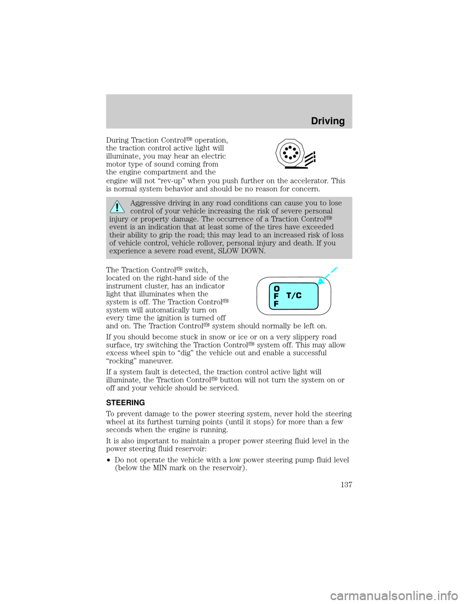
During Traction Controlyoperation,
the traction control active light will
illuminate, you may hear an electric
motor type of sound coming from
the engine compartment and the
engine will not ªrev-upº when you push further on the accelerator. This
is normal system behavior and should be no reason for concern.
Aggressive driving in any road conditions can cause you to lose
control of your vehicle increasing the risk of severe personal
injury or property damage. The occurrence of a Traction Controly
event is an indication that at least some of the tires have exceeded
their ability to grip the road; this may lead to an increased risk of loss
of vehicle control, vehicle rollover, personal injury and death. If you
experience a severe road event, SLOW DOWN.
The Traction Controlyswitch,
located on the right-hand side of the
instrument cluster, has an indicator
light that illuminates when the
system is off. The Traction Controly
system will automatically turn on
every time the ignition is turned off
and on. The Traction Controlysystem should normally be left on.
If you should become stuck in snow or ice or on a very slippery road
surface, try switching the Traction Controlysystem off. This may allow
excess wheel spin to ªdigº the vehicle out and enable a successful
ªrockingº maneuver.
If a system fault is detected, the traction control active light will
illuminate, the Traction Controlybutton will not turn the system on or
off and your vehicle should be serviced.
STEERING
To prevent damage to the power steering system, never hold the steering
wheel at its furthest turning points (until it stops) for more than a few
seconds when the engine is running.
It is also important to maintain a proper power steering fluid level in the
power steering fluid reservoir:
²Do not operate the vehicle with a low power steering pump fluid level
(below the MIN mark on the reservoir).
T/C O
F
F
Driving
137