ECU FORD TAURUS 2005 4.G Owners Manual
[x] Cancel search | Manufacturer: FORD, Model Year: 2005, Model line: TAURUS, Model: FORD TAURUS 2005 4.GPages: 248, PDF Size: 2.66 MB
Page 1 of 248
Introduction 4
Instrument Cluster 10
Warning and control lights 10
Gauges 13
Entertainment Systems 15
AM/FM stereo 15
AM/FM stereo cassette 16
AM/FM stereo with CD 19
CD changer 21
Climate Controls 24
Manual heating and air conditioning 24
Electronic automatic temperature control 26
Rear window defroster 28
Lights 30
Headlamps 30
Turn signal control 33
Bulb replacement 35
Driver Controls 46
Windshield wiper/washer control 46
Steering wheel adjustment 47
Power windows 48
Mirrors 50
Speed control 51
Message center 58
Locks and Security 73
Keys 73
Locks 73
Anti-theft system 83
Table of Contents
1
Table of Contents
Page 12 of 248
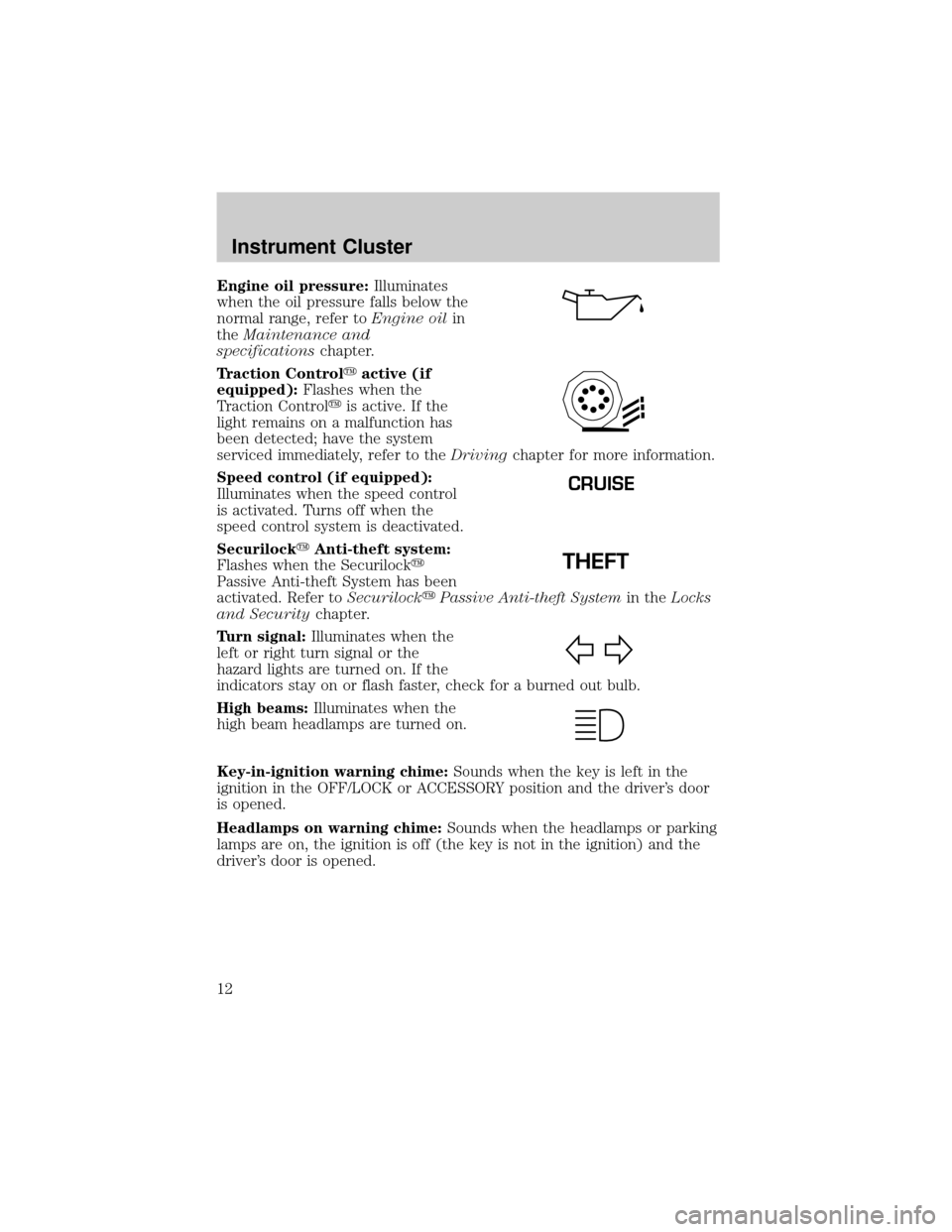
Engine oil pressure:Illuminates
when the oil pressure falls below the
normal range, refer toEngine oilin
theMaintenance and
specificationschapter.
Traction Controlyactive (if
equipped):Flashes when the
Traction Controlyis active. If the
light remains on a malfunction has
been detected; have the system
serviced immediately, refer to theDrivingchapter for more information.
Speed control (if equipped):
Illuminates when the speed control
is activated. Turns off when the
speed control system is deactivated.
SecurilockyAnti-theft system:
Flashes when the Securilocky
Passive Anti-theft System has been
activated. Refer toSecurilockyPassive Anti-theft Systemin theLocks
and Securitychapter.
Turn signal:Illuminates when the
left or right turn signal or the
hazard lights are turned on. If the
indicators stay on or flash faster, check for a burned out bulb.
High beams:Illuminates when the
high beam headlamps are turned on.
Key-in-ignition warning chime:Sounds when the key is left in the
ignition in the OFF/LOCK or ACCESSORY position and the driver's door
is opened.
Headlamps on warning chime:Sounds when the headlamps or parking
lamps are on, the ignition is off (the key is not in the ignition) and the
driver's door is opened.
CRUISE
Instrument Cluster
12
Page 22 of 248
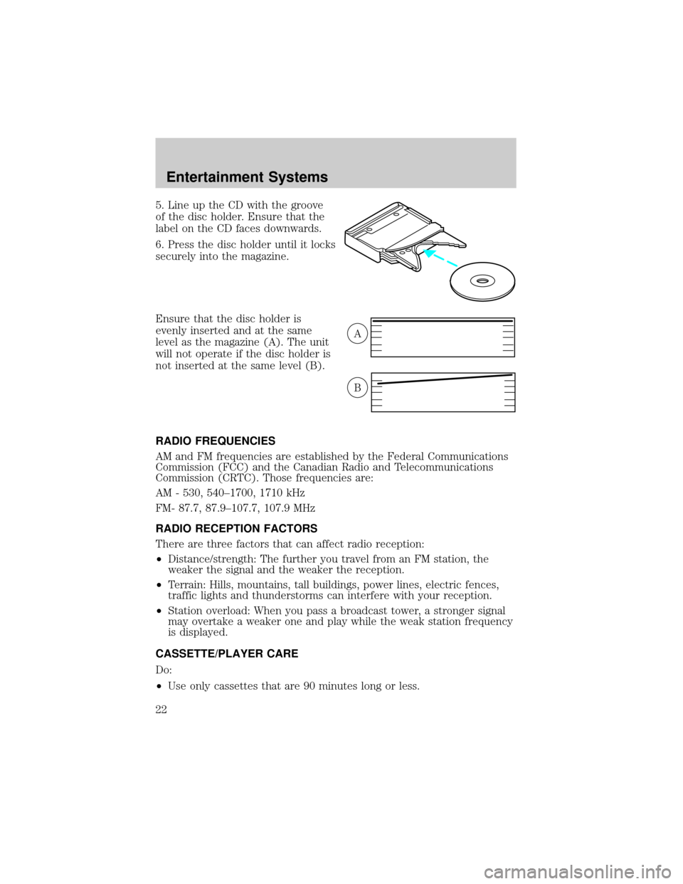
5. Line up the CD with the groove
of the disc holder. Ensure that the
label on the CD faces downwards.
6. Press the disc holder until it locks
securely into the magazine.
Ensure that the disc holder is
evenly inserted and at the same
level as the magazine (A). The unit
will not operate if the disc holder is
not inserted at the same level (B).
RADIO FREQUENCIES
AM and FM frequencies are established by the Federal Communications
Commission (FCC) and the Canadian Radio and Telecommunications
Commission (CRTC). Those frequencies are:
AM - 530, 540±1700, 1710 kHz
FM- 87.7, 87.9±107.7, 107.9 MHz
RADIO RECEPTION FACTORS
There are three factors that can affect radio reception:
²Distance/strength: The further you travel from an FM station, the
weaker the signal and the weaker the reception.
²Terrain: Hills, mountains, tall buildings, power lines, electric fences,
traffic lights and thunderstorms can interfere with your reception.
²Station overload: When you pass a broadcast tower, a stronger signal
may overtake a weaker one and play while the weak station frequency
is displayed.
CASSETTE/PLAYER CARE
Do:
²Use only cassettes that are 90 minutes long or less.
A
B
Entertainment Systems
22
Page 43 of 248
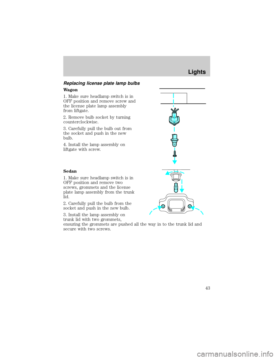
Replacing license plate lamp bulbs
Wagon
1. Make sure headlamp switch is in
OFF position and remove screw and
the license plate lamp assembly
from liftgate.
2. Remove bulb socket by turning
counterclockwise.
3. Carefully pull the bulb out from
the socket and push in the new
bulb.
4. Install the lamp assembly on
liftgate with screw.
Sedan
1. Make sure headlamp switch is in
OFF position and remove two
screws, grommets and the license
plate lamp assembly from the trunk
lid.
2. Carefully pull the bulb from the
socket and push in the new bulb.
3. Install the lamp assembly on
trunk lid with two grommets,
ensuring the grommets are pushed all the way in to the trunk lid and
secure with two screws.
Lights
43
Page 45 of 248
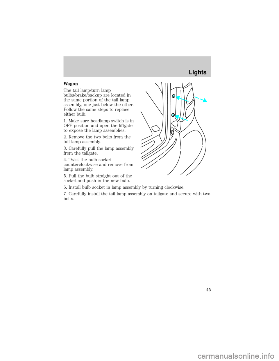
Wagon
The tail lamp/turn lamp
bulbs/brake/backup are located in
the same portion of the tail lamp
assembly, one just below the other.
Follow the same steps to replace
either bulb:
1. Make sure headlamp switch is in
OFF position and open the liftgate
to expose the lamp assemblies.
2. Remove the two bolts from the
tail lamp assembly.
3. Carefully pull the lamp assembly
from the tailgate.
4. Twist the bulb socket
counterclockwise and remove from
lamp assembly.
5. Pull the bulb straight out of the
socket and push in the new bulb.
6. Install bulb socket in lamp assembly by turning clockwise.
7. Carefully install the tail lamp assembly on tailgate and secure with two
bolts.
Lights
45
Page 55 of 248
with a single built-in device. This feature will learn the radio frequency
codes of most transmitters to operate garage doors, entry gate operators,
security systems, entry door locks, and home or office lighting.
When programming your HomeLinktWireless Control System to
a garage door or gate, be sure that people and objects are out of
the way to prevent potential harm or damage.
Do not use the HomeLinktWireless Control System with any garage
door opener that lacks safety stop and reverse features as required by
U.S. federal safety standards (this includes any garage door opener
model manufactured before April 1, 1982). A garage door which cannot
detect an object, signaling the door to stop and reverse, does not meet
current U.S. federal safety standards. For more information, contact
HomeLinktat:www.homelink.comor1±800±355±3515.
Retain the original transmitter for use in other vehicles as well as for
future programming procedures (i.e. new HomeLinktequipped vehicle
purchase). It is also suggested that upon the sale of the vehicle, the
programmed Homelinktbuttons be erased for security purposes, refer to
Programmingin this section.
Programming
Do not program HomeLinktwith the vehicle parked in the garage.
Note:Your vehicle may require the ignition switch to be turned to the
ACC position for programming and/or operation of the HomeLinkt.Itis
also recommended that a new battery be placed in the hand-held
transmitter of the device being programmed to HomeLinktfor quicker
training and accurate transmission of the radio-frequency signal.
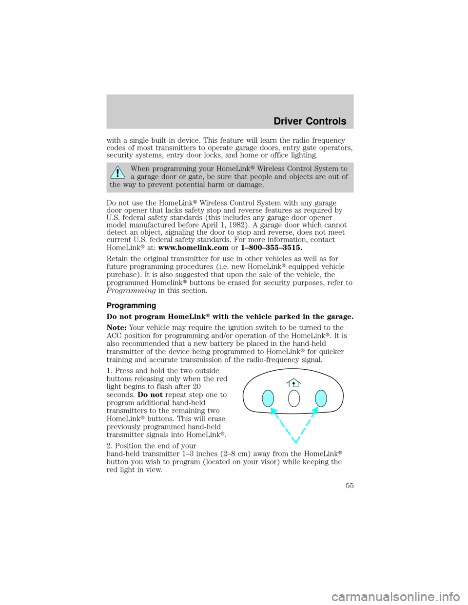
1. Press and hold the two outside
buttons releasing only when the red
light begins to flash after 20
seconds.Do notrepeat step one to
program additional hand-held
transmitters to the remaining two
HomeLinktbuttons. This will erase
previously programmed hand-held
transmitter signals into HomeLinkt.
2. Position the end of your
hand-held transmitter 1±3 inches (2±8 cm) away from the HomeLinkt
button you wish to program (located on your visor) while keeping the
red light in view.
Driver Controls
55
Page 57 of 248
Gate Operator & Canadian Programming
During programming, your
hand-held transmitter may
automatically stop transmitting Ð
not allowing enough time for
HomeLinktto accept the signal
from the hand-held transmitter.
After completing steps 1 and 2
outlined in theªProgrammingº
section, replace step 3 with the following:
Note:If programming a garage door opener or gate operator, it is
advised to unplug the device during the ªcyclingº process to prevent
overheating.
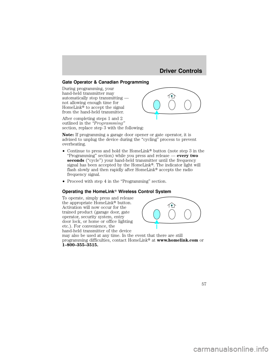
²Continue to press and hold the HomeLinktbutton (note step 3 in the
ªProgrammingº section) while you press and release Ðevery two
seconds(ªcycleº) your hand-held transmitter until the frequency
signal has been accepted by the HomeLinkt. The indicator light will
flash slowly and then rapidly after HomeLinktaccepts the radio
frequency signal.
²Proceed with step 4 in the ªProgrammingº section.
Operating the HomeLinkTWireless Control System
To operate, simply press and release
the appropriate HomeLinktbutton.
Activation will now occur for the
trained product (garage door, gate
operator, security system, entry
door lock, or home or office lighting
etc.). For convenience, the
hand-held transmitter of the device
may also be used at any time. In the event that there are still
programming difficulties, contact HomeLinktatwww.homelink.comor
1±800±355±3515.
Driver Controls
57
Page 68 of 248
²Coin holder slots
²Compact disc changer (if equipped)
²Tissue holder
²Rear ashtray (see your Ford, Lincoln Mercury dealer to obtain rear
ashtray
Use only soft cups in the cupholder. Hard objects can injure you
in a collision.
If your vehicle is equipped with the column shift and a bench seat, it has
a center console in the center front seating position.
The center console has similar features as the full console. To open the
storage compartment, raise the armrest and pull the strap on the seat up
and toward the front of the vehicle. The rear seat area is provided with
dual cupholders.
CELL PHONE USE
The use of Mobile Communications Equipment has become increasingly
important in the conduct of business and personal affairs. However,
drivers must not compromise their own or others' safety when using
such equipment. Mobile Communications can enhance personal safety
and security when appropriately used, particularly in emergency
situations. Safety must be paramount when using mobile communications
equipment to avoid negating these benefits.
Mobile Communication Equipment includes, but is not limited to cellular
phones, pagers, portable email devices, in vehicle communications
systems, telematics devices and portable two-way radios.
A driver's first responsibility is the safe operation of the vehicle.
The most important thing you can do to prevent a crash is to
avoid distractions and pay attention to the road. Wait until it is safe to
operate Mobile Communications Equipment.
Driver Controls
68
Page 70 of 248
The liftgate and liftgate window should be closed before driving your
vehicle. If not, possible damage may occur to the liftgate lift cylinders
and attaching hardware.
CARGO AREA FEATURES
Storage compartment (Wagon)
Your vehicle comes equipped with a storage compartment in the floor of
the cargo area. An additional compartment is in the rear trim panel on
the right. Always put the load you are carrying as far forward as possible.
Cargo net (if equipped) (Wagon)
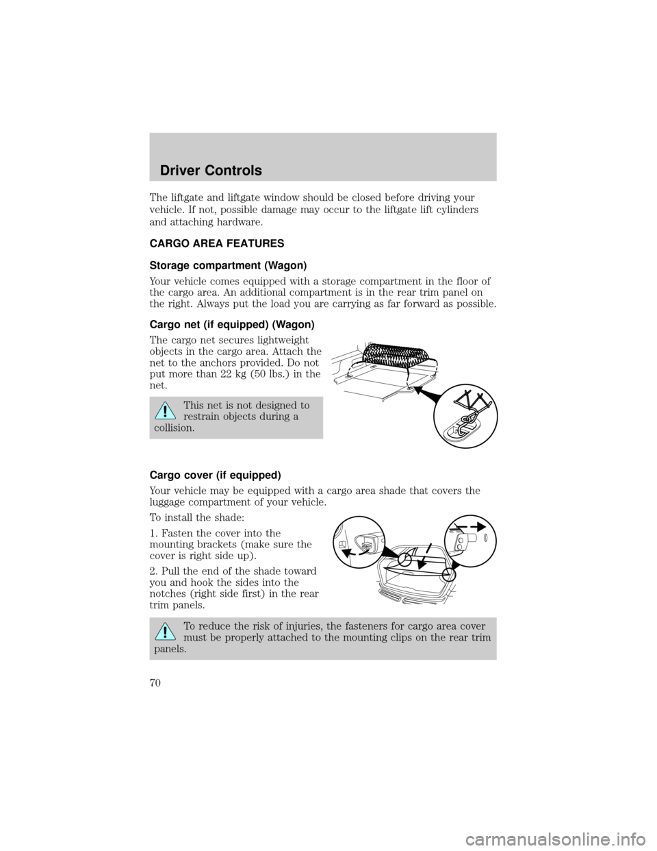
The cargo net secures lightweight
objects in the cargo area. Attach the
net to the anchors provided. Do not
put more than 22 kg (50 lbs.) in the
net.
This net is not designed to
restrain objects during a
collision.
Cargo cover (if equipped)
Your vehicle may be equipped with a cargo area shade that covers the
luggage compartment of your vehicle.
To install the shade:
1. Fasten the cover into the
mounting brackets (make sure the
cover is right side up).
2. Pull the end of the shade toward
you and hook the sides into the
notches (right side first) in the rear
trim panels.
To reduce the risk of injuries, the fasteners for cargo area cover
must be properly attached to the mounting clips on the rear trim
panels.
Driver Controls
70
Page 71 of 248
Do not place any objects on the cargo area cover. They may
obstruct your vision or strike occupants of the vehicle in the
case of a sudden stop or collision.
The cover may cause injury in a sudden stop or accident if it is
not securely installed.
Rewinding the shade
With extended use, the cargo shade may lose its spring tension. If this
occurs, the shade must be manually rewound. This is a two-person
operation.
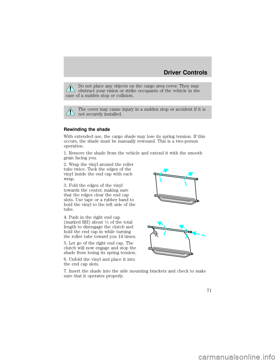
1. Remove the shade from the vehicle and extend it with the smooth
grain facing you.
2. Wrap the vinyl around the roller
tube twice. Tuck the edges of the
vinyl inside the end cap with each
wrap.
3. Fold the edges of the vinyl
towards the center, making sure
that the edges clear the end cap
slots. Use tape or a rubber band to
hold the vinyl to the left side of the
tube.
4. Push in the right end cap
(marked RH) about
1¤4of the total
length to disengage the clutch and
hold the end cap in while turning
the roller tube toward you 14 times.
5. Let go of the right end cap. The
clutch will now engage and stop the
shade from losing its spring tension.
6. Unfold the vinyl and place it into
the end cap slots.
7. Insert the shade into the side mounting brackets and check to make
sure that it operates properly.
Driver Controls
71