turn signal FORD TAURUS 2005 4.G Owners Manual
[x] Cancel search | Manufacturer: FORD, Model Year: 2005, Model line: TAURUS, Model: FORD TAURUS 2005 4.GPages: 248, PDF Size: 2.66 MB
Page 1 of 248
Introduction 4
Instrument Cluster 10
Warning and control lights 10
Gauges 13
Entertainment Systems 15
AM/FM stereo 15
AM/FM stereo cassette 16
AM/FM stereo with CD 19
CD changer 21
Climate Controls 24
Manual heating and air conditioning 24
Electronic automatic temperature control 26
Rear window defroster 28
Lights 30
Headlamps 30
Turn signal control 33
Bulb replacement 35
Driver Controls 46
Windshield wiper/washer control 46
Steering wheel adjustment 47
Power windows 48
Mirrors 50
Speed control 51
Message center 58
Locks and Security 73
Keys 73
Locks 73
Anti-theft system 83
Table of Contents
1
Table of Contents
Page 12 of 248
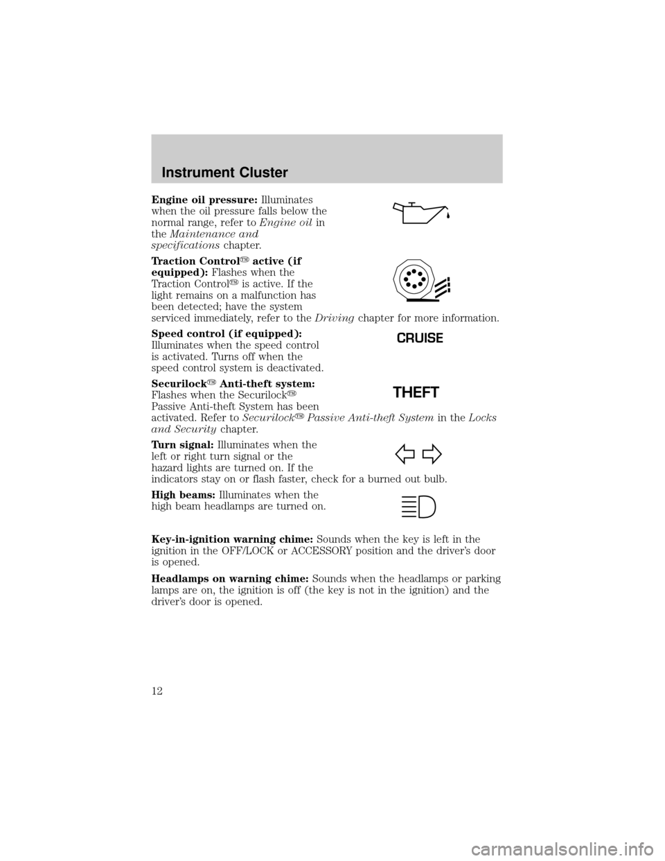
Engine oil pressure:Illuminates
when the oil pressure falls below the
normal range, refer toEngine oilin
theMaintenance and
specificationschapter.
Traction Controlyactive (if
equipped):Flashes when the
Traction Controlyis active. If the
light remains on a malfunction has
been detected; have the system
serviced immediately, refer to theDrivingchapter for more information.
Speed control (if equipped):
Illuminates when the speed control
is activated. Turns off when the
speed control system is deactivated.
SecurilockyAnti-theft system:
Flashes when the Securilocky
Passive Anti-theft System has been
activated. Refer toSecurilockyPassive Anti-theft Systemin theLocks
and Securitychapter.
Turn signal:Illuminates when the
left or right turn signal or the
hazard lights are turned on. If the
indicators stay on or flash faster, check for a burned out bulb.
High beams:Illuminates when the
high beam headlamps are turned on.
Key-in-ignition warning chime:Sounds when the key is left in the
ignition in the OFF/LOCK or ACCESSORY position and the driver's door
is opened.
Headlamps on warning chime:Sounds when the headlamps or parking
lamps are on, the ignition is off (the key is not in the ignition) and the
driver's door is opened.
CRUISE
Instrument Cluster
12
Page 33 of 248
To see a clearer light pattern for
adjusting, you may want to block
the light from one headlamp while
adjusting the other.
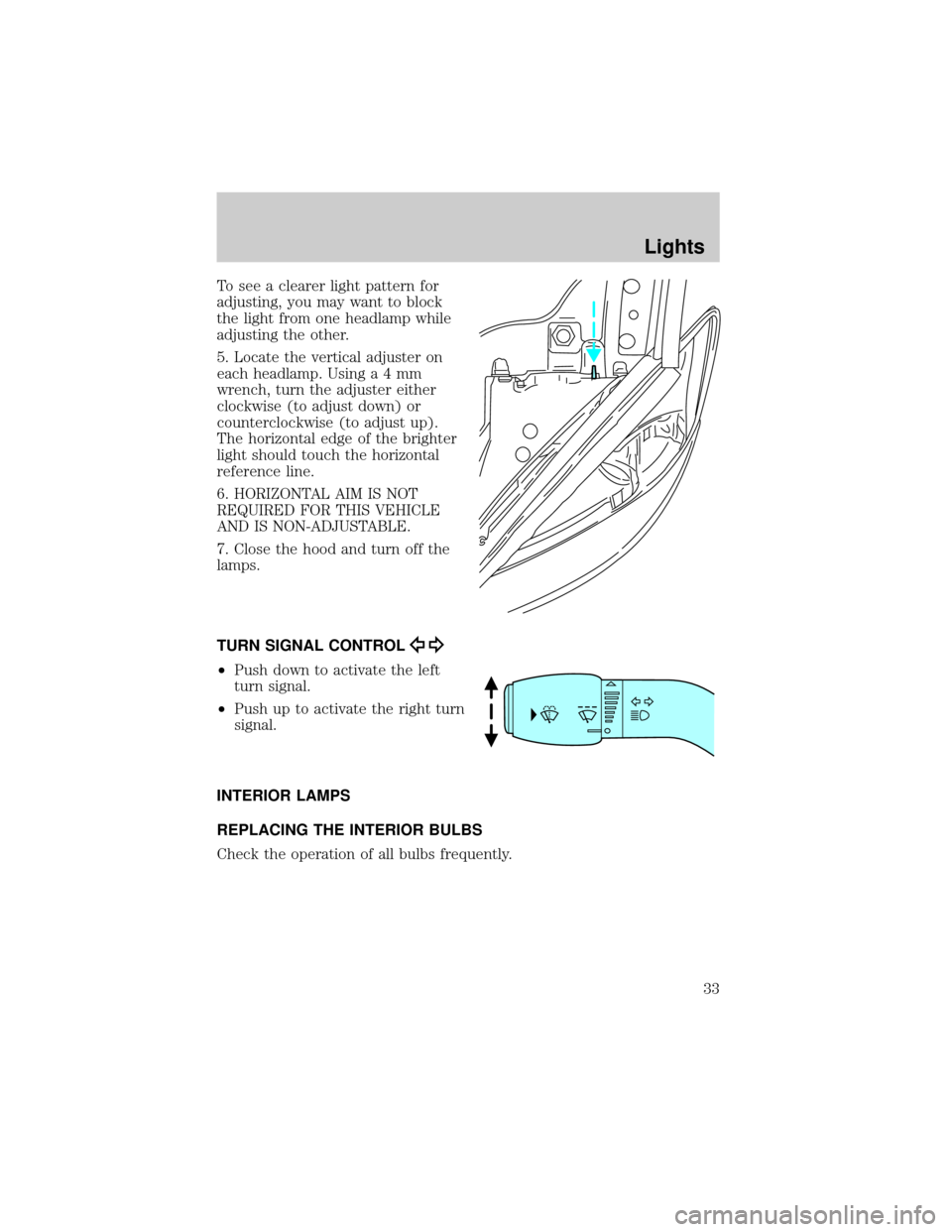
5. Locate the vertical adjuster on
each headlamp. Usinga4mm
wrench, turn the adjuster either
clockwise (to adjust down) or
counterclockwise (to adjust up).
The horizontal edge of the brighter
light should touch the horizontal
reference line.
6. HORIZONTAL AIM IS NOT
REQUIRED FOR THIS VEHICLE
AND IS NON-ADJUSTABLE.
7. Close the hood and turn off the
lamps.
TURN SIGNAL CONTROL
²Push down to activate the left
turn signal.
²Push up to activate the right turn
signal.
INTERIOR LAMPS
REPLACING THE INTERIOR BULBS
Check the operation of all bulbs frequently.
Lights
33
Page 39 of 248
2. Install the bulb retaining ring over the plastic base and lock the ring
by rotating clockwise until it snaps into place.
3. Connect the electrical connector to the bulb.
4. Install the protective dust shield and lock the shield by rotating it
clockwise until it locks into position.
5. Carefully position the headlamp assembly onto the vehicle.
6. Hold the headlamp assembly snugly against the vehicle and install the
retainer pins straight down to lock the lamp into place.
7. Before reinstalling the bolt, make sure the retainer pins are fully
seated, and install bolt on headlamp housing.
8. Turn the headlamps on and make sure they work properly. If the
headlamp was correctly aligned before you changed the bulb, you should
not need to align it again.
Replacing front parking lamp/turn signal/cornering lamp bulbs
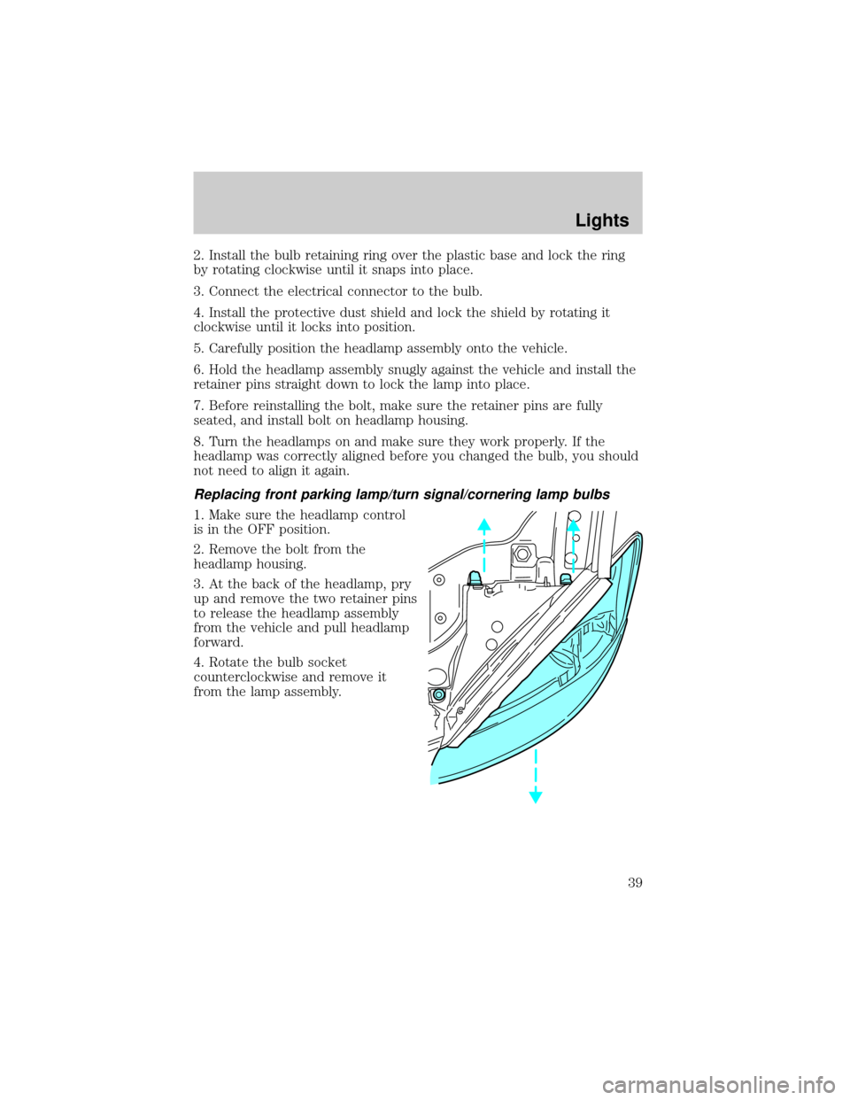
1. Make sure the headlamp control
is in the OFF position.
2. Remove the bolt from the
headlamp housing.
3. At the back of the headlamp, pry
up and remove the two retainer pins
to release the headlamp assembly
from the vehicle and pull headlamp
forward.
4. Rotate the bulb socket
counterclockwise and remove it
from the lamp assembly.
Lights
39
Page 44 of 248
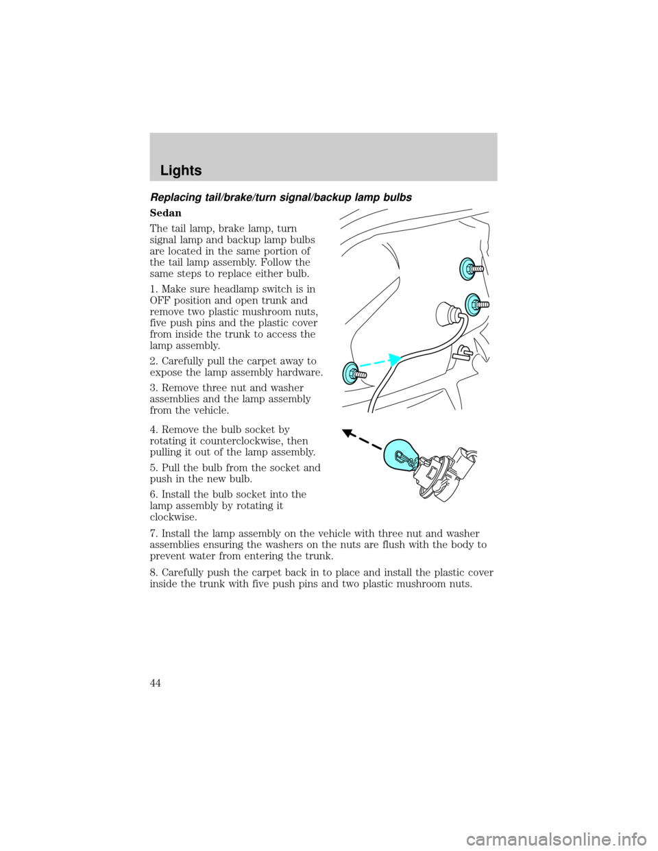
Replacing tail/brake/turn signal/backup lamp bulbs
Sedan
The tail lamp, brake lamp, turn
signal lamp and backup lamp bulbs
are located in the same portion of
the tail lamp assembly. Follow the
same steps to replace either bulb.
1. Make sure headlamp switch is in
OFF position and open trunk and
remove two plastic mushroom nuts,
five push pins and the plastic cover
from inside the trunk to access the
lamp assembly.
2. Carefully pull the carpet away to
expose the lamp assembly hardware.
3. Remove three nut and washer
assemblies and the lamp assembly
from the vehicle.
4. Remove the bulb socket by
rotating it counterclockwise, then
pulling it out of the lamp assembly.
5. Pull the bulb from the socket and
push in the new bulb.
6. Install the bulb socket into the
lamp assembly by rotating it
clockwise.
7. Install the lamp assembly on the vehicle with three nut and washer
assemblies ensuring the washers on the nuts are flush with the body to
prevent water from entering the trunk.
8. Carefully push the carpet back in to place and install the plastic cover
inside the trunk with five push pins and two plastic mushroom nuts.
Lights
44
Page 55 of 248
with a single built-in device. This feature will learn the radio frequency
codes of most transmitters to operate garage doors, entry gate operators,
security systems, entry door locks, and home or office lighting.
When programming your HomeLinktWireless Control System to
a garage door or gate, be sure that people and objects are out of
the way to prevent potential harm or damage.
Do not use the HomeLinktWireless Control System with any garage
door opener that lacks safety stop and reverse features as required by
U.S. federal safety standards (this includes any garage door opener
model manufactured before April 1, 1982). A garage door which cannot
detect an object, signaling the door to stop and reverse, does not meet
current U.S. federal safety standards. For more information, contact
HomeLinktat:www.homelink.comor1±800±355±3515.
Retain the original transmitter for use in other vehicles as well as for
future programming procedures (i.e. new HomeLinktequipped vehicle
purchase). It is also suggested that upon the sale of the vehicle, the
programmed Homelinktbuttons be erased for security purposes, refer to
Programmingin this section.
Programming
Do not program HomeLinktwith the vehicle parked in the garage.
Note:Your vehicle may require the ignition switch to be turned to the
ACC position for programming and/or operation of the HomeLinkt.Itis
also recommended that a new battery be placed in the hand-held
transmitter of the device being programmed to HomeLinktfor quicker
training and accurate transmission of the radio-frequency signal.
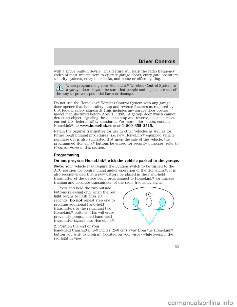
1. Press and hold the two outside
buttons releasing only when the red
light begins to flash after 20
seconds.Do notrepeat step one to
program additional hand-held
transmitters to the remaining two
HomeLinktbuttons. This will erase
previously programmed hand-held
transmitter signals into HomeLinkt.
2. Position the end of your
hand-held transmitter 1±3 inches (2±8 cm) away from the HomeLinkt
button you wish to program (located on your visor) while keeping the
red light in view.
Driver Controls
55
Page 56 of 248
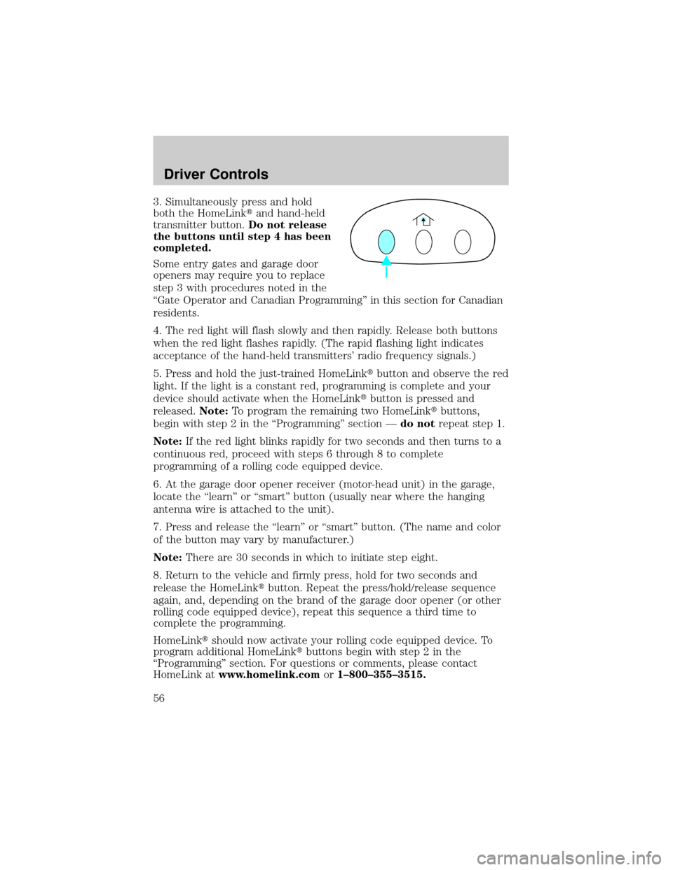
3. Simultaneously press and hold
both the HomeLinktand hand-held
transmitter button.Do not release
the buttons until step 4 has been
completed.
Some entry gates and garage door
openers may require you to replace
step 3 with procedures noted in the
ªGate Operator and Canadian Programmingº in this section for Canadian
residents.
4. The red light will flash slowly and then rapidly. Release both buttons
when the red light flashes rapidly. (The rapid flashing light indicates
acceptance of the hand-held transmitters' radio frequency signals.)
5. Press and hold the just-trained HomeLinktbutton and observe the red
light. If the light is a constant red, programming is complete and your
device should activate when the HomeLinktbutton is pressed and
released.Note:To program the remaining two HomeLinktbuttons,
begin with step 2 in the ªProgrammingº section Ðdo notrepeat step 1.
Note:If the red light blinks rapidly for two seconds and then turns to a
continuous red, proceed with steps 6 through 8 to complete
programming of a rolling code equipped device.
6. At the garage door opener receiver (motor-head unit) in the garage,
locate the ªlearnº or ªsmartº button (usually near where the hanging
antenna wire is attached to the unit).
7. Press and release the ªlearnº or ªsmartº button. (The name and color
of the button may vary by manufacturer.)
Note:There are 30 seconds in which to initiate step eight.
8. Return to the vehicle and firmly press, hold for two seconds and
release the HomeLinktbutton. Repeat the press/hold/release sequence
again, and, depending on the brand of the garage door opener (or other
rolling code equipped device), repeat this sequence a third time to
complete the programming.
HomeLinktshould now activate your rolling code equipped device. To
program additional HomeLinktbuttons begin with step 2 in the
ªProgrammingº section. For questions or comments, please contact
HomeLink atwww.homelink.comor1±800±355±3515.
Driver Controls
56
Page 147 of 248
Towing trailers beyond the maximum recommended gross trailer
weight exceeds the limit of the vehicle and could result in
engine damage, transaxle damage, structural damage, loss of control,
and personal injury.
Preparing to tow
Use the proper equipment for towing a trailer and make sure it is
properly attached to your vehicle. See your dealer or a reliable trailer
dealer if you require assistance.
Hitches
Do not use hitches that clamp onto the vehicle bumper. Use a load
carrying hitch. You must distribute the load in your trailer so that
10±15% of the total weight of the trailer is on the tongue.
Safety chains
Always connect the trailer's safety chains to the frame or hook retainers
of the vehicle hitch. To connect the trailer's safety chains, cross the
chains under the trailer tongue and allow slack for turning corners.
If you use a rental trailer, follow the instructions that the rental agency
gives to you.
Do not attach safety chains to the bumper.
Trailer brakes
Electric brakes and manual, automatic or surge-type trailer brakes are
safe if installed properly and adjusted to the manufacturer's
specifications. The trailer brakes must meet local and Federal
regulations.
Do not connect a trailer's hydraulic brake system directly to your
vehicle's brake system. Your vehicle may not have enough
braking power and your chances of having a collision greatly increase.
The braking system of the tow vehicle is rated for operation at the
GVWR not GCWR.
Trailer lamps
Trailer lamps are required on most towed vehicles. Make sure all running
lights, brake lights, turn signals and hazard lights are working. See your
dealer or trailer rental agency for proper instructions and equipment for
hooking up trailer lamps.
Driving
147
Page 151 of 248
Canadian customers who require roadside assistance, call
1±800±665±2006.
If you need to arrange roadside assistance for yourself, Ford Motor
Company will reimburse a reasonable amount. To obtain reimbursement
information, U.S. Ford or Mercury vehicles customers call
1-800-241-3673; Lincoln vehicle customers call 1±800±521±4140.
Canadian customers who need to obtain reimbursement information, call
1±800±665±2006.
ROADSIDE COVERAGE BEYOND BASIC WARRANTY
In the United States, you may purchase additional roadside assistance
coverage beyond this period through the Ford Auto Club by contacting
your Ford or Lincoln Mercury dealer.
Similarly in Canada, for uninterrupted Roadside Assistance coverage, you
may purchase extended coverage prior to your Basic Warranty's Roadside
Assistance expiring. For more information and enrollment, contact
1±877±294±2582 or visit our website at www.ford.ca.
HAZARD FLASHER
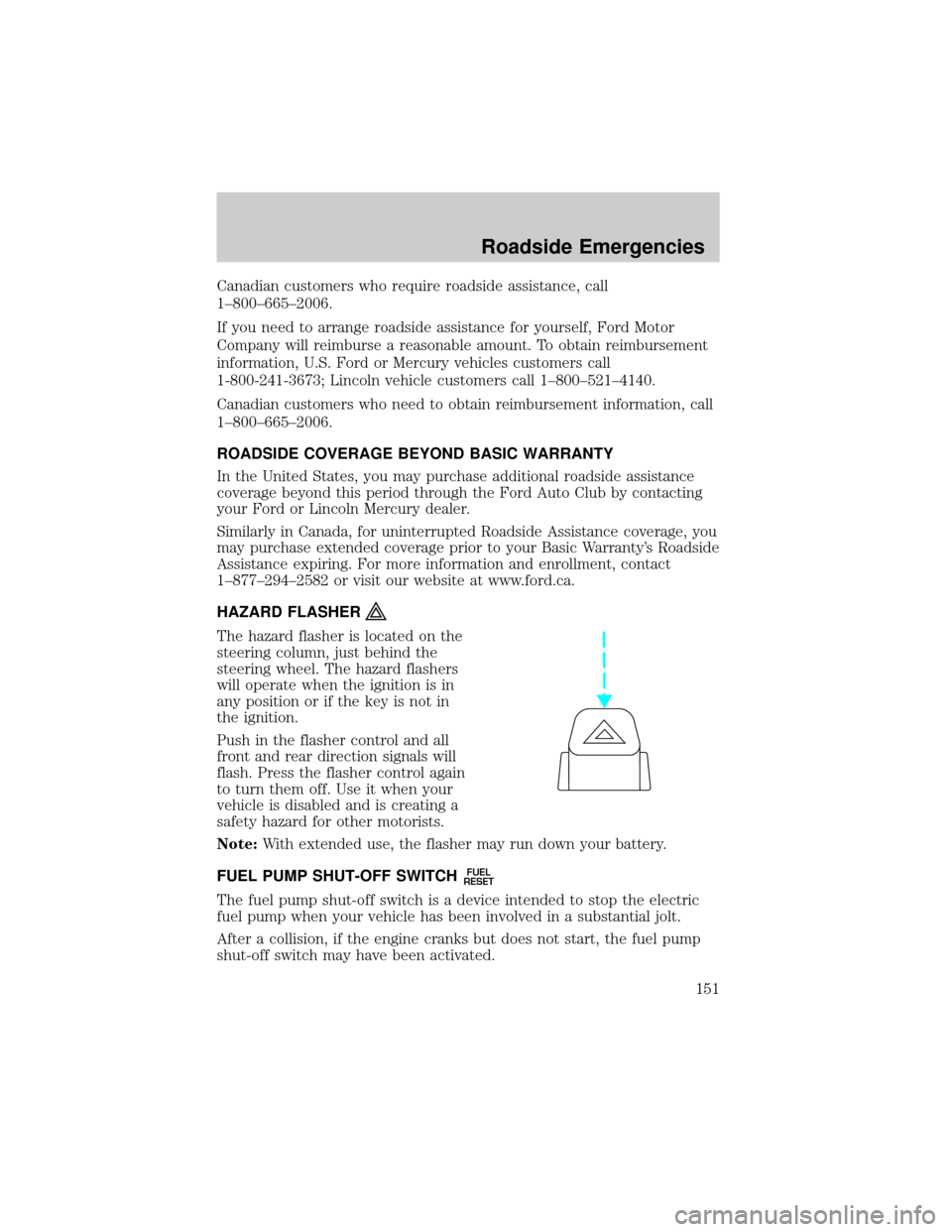
The hazard flasher is located on the
steering column, just behind the
steering wheel. The hazard flashers
will operate when the ignition is in
any position or if the key is not in
the ignition.
Push in the flasher control and all
front and rear direction signals will
flash. Press the flasher control again
to turn them off. Use it when your
vehicle is disabled and is creating a
safety hazard for other motorists.
Note:With extended use, the flasher may run down your battery.
FUEL PUMP SHUT-OFF SWITCH
FUEL
RESET
The fuel pump shut-off switch is a device intended to stop the electric
fuel pump when your vehicle has been involved in a substantial jolt.
After a collision, if the engine cranks but does not start, the fuel pump
shut-off switch may have been activated.
Roadside Emergencies
151
Page 155 of 248
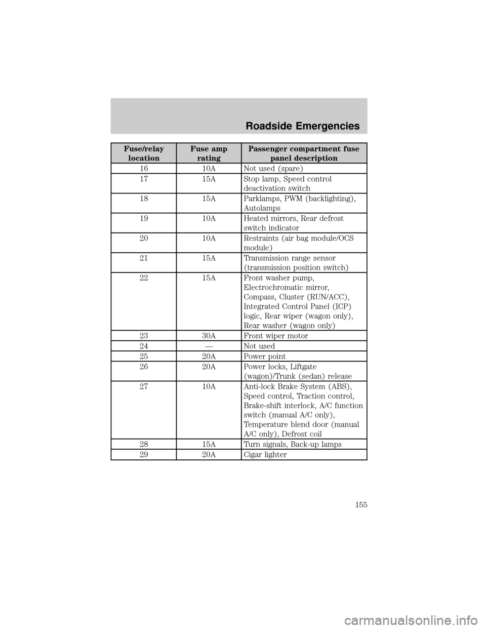
Fuse/relay
locationFuse amp
ratingPassenger compartment fuse
panel description
16 10A Not used (spare)
17 15A Stop lamp, Speed control
deactivation switch
18 15A Parklamps, PWM (backlighting),
Autolamps
19 10A Heated mirrors, Rear defrost
switch indicator
20 10A Restraints (air bag module/OCS
module)
21 15A Transmission range sensor
(transmission position switch)
22 15A Front washer pump,
Electrochromatic mirror,
Compass, Cluster (RUN/ACC),
Integrated Control Panel (ICP)
logic, Rear wiper (wagon only),
Rear washer (wagon only)
23 30A Front wiper motor
24 Ð Not used
25 20A Power point
26 20A Power locks, Liftgate
(wagon)/Trunk (sedan) release
27 10A Anti-lock Brake System (ABS),
Speed control, Traction control,
Brake-shift interlock, A/C function
switch (manual A/C only),
Temperature blend door (manual
A/C only), Defrost coil
28 15A Turn signals, Back-up lamps
29 20A Cigar lighter
Roadside Emergencies
155