battery FORD THUNDERBIRD 2003 11.G User Guide
[x] Cancel search | Manufacturer: FORD, Model Year: 2003, Model line: THUNDERBIRD, Model: FORD THUNDERBIRD 2003 11.GPages: 200, PDF Size: 1.79 MB
Page 61 of 200
•after 25 seconds of illumination.
The inside lights will not turn off if:
•they have been turned on with the dimmer control, or
•any door is open.
The battery saver will shut off the interior lamps 30 minutes after the
ignition has been turned to the OFF position.
Autolock
The autolock feature will lock the vehicle’s doors when:
•all the doors are closed,
•the ignition is in the RUN position, and
•you shift into forward or reverse, putting the vehicle in motion.
Relock
The autolock feature repeats when:
•either door is opened then closed while the ignition is in the RUN
position,
•you shift into forward or reverse, and
•you put the vehicle in motion by releasing the brake pedal.
Deactivating/activating autolock
Your vehicle comes with the autolock feature activated. There are two
methods to enable/disable this feature: One is through your dealer, and
the second is using a power door unlock/lock sequence.
Before following the activation or deactivation procedures, make sure
that the anti-theft system is not activated, ignition is off, and the vehicle
doors are closed.
Power door unlock/lock procedure
You must complete steps 1-5 within
30 seconds or the procedure will
have to be repeated.
1. Turn the ignition to the RUN
position.
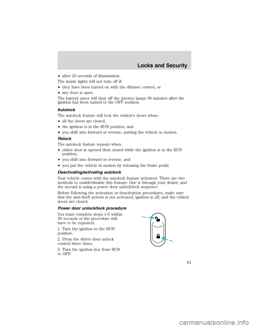
2. Press the driver door unlock
control three times.
3. Turn the ignition key from RUN
to OFF.
Locks and Security
61
Page 109 of 200
Always set the parking brake fully and make sure the gearshift is
latched in P (Park). Turn the ignition to the LOCK position and
remove the key whenever you leave your vehicle.
If the parking brake is fully released, but the brake warning lamp
remains illuminated, the brakes may not be working properly.
See your dealer or a qualified service technician.
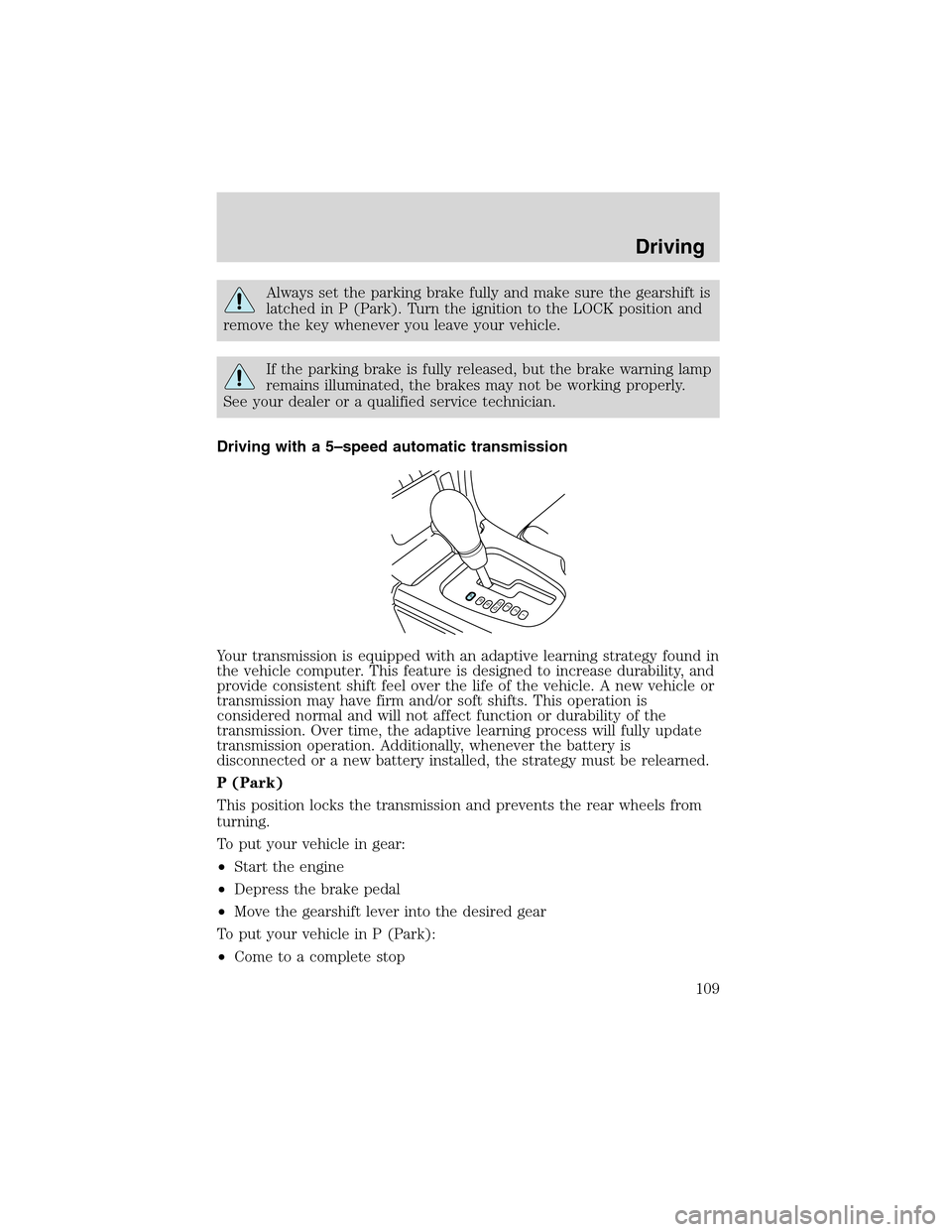
Driving with a 5–speed automatic transmission
Your transmission is equipped with an adaptive learning strategy found in
the vehicle computer. This feature is designed to increase durability, and
provide consistent shift feel over the life of the vehicle. A new vehicle or
transmission may have firm and/or soft shifts. This operation is
considered normal and will not affect function or durability of the
transmission. Over time, the adaptive learning process will fully update
transmission operation. Additionally, whenever the battery is
disconnected or a new battery installed, the strategy must be relearned.
P (Park)
This position locks the transmission and prevents the rear wheels from
turning.
To put your vehicle in gear:
•Start the engine
•Depress the brake pedal
•Move the gearshift lever into the desired gear
To put your vehicle in P (Park):
•Come to a complete stop
PRND5D4321
Driving
109
Page 117 of 200
U.S. Ford or Mercury vehicle customers who require roadside assistance,
call 1–800–241–3673; Lincoln vehicle customers call 1–800–521–4140.
Canadian customers who require roadside assistance, call
1–800–665–2006.
If you need to arrange roadside assistance for yourself, Ford Motor
Company will reimburse a reasonable amount. To obtain reimbursement
information, U.S. Ford or Mercury vehicles customers call
1-800-241-3673; Lincoln vehicle customers call 1–800–521–4140.
Canadian customers who need to obtain reimbursement information, call
1–800–665–2006.
Roadside coverage beyond basic warranty
In the United States, you may purchase additional roadside assistance
coverage beyond this period through the Ford Auto Club by contacting
your Ford or Lincoln Mercury dealer.
Similarly in Canada, for uninterrupted Roadside Assistance coverage, you
may purchase extended coverage prior to your Basic Warranty’s Roadside
Assistance expiring. For more information and enrollment, contact
1–877–294–2582 or visit our website at www.ford.ca.
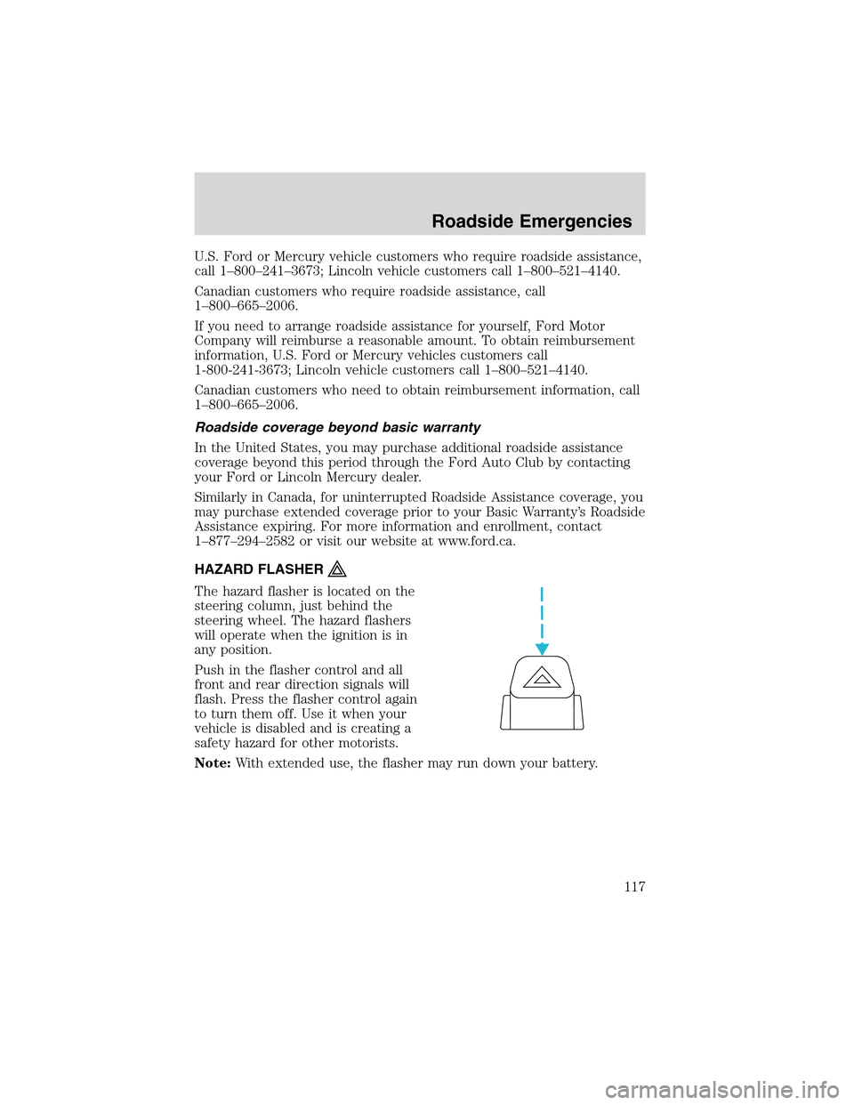
HAZARD FLASHER
The hazard flasher is located on the
steering column, just behind the
steering wheel. The hazard flashers
will operate when the ignition is in
any position.
Push in the flasher control and all
front and rear direction signals will
flash. Press the flasher control again
to turn them off. Use it when your
vehicle is disabled and is creating a
safety hazard for other motorists.
Note:With extended use, the flasher may run down your battery.
Roadside Emergencies
117
Page 122 of 200
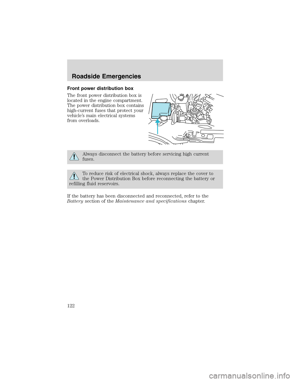
Front power distribution box
The front power distribution box is
located in the engine compartment.
The power distribution box contains
high-current fuses that protect your
vehicle’s main electrical systems
from overloads.
Always disconnect the battery before servicing high current
fuses.
To reduce risk of electrical shock, always replace the cover to
the Power Distribution Box before reconnecting the battery or
refilling fluid reservoirs.
If the battery has been disconnected and reconnected, refer to the
Batterysection of theMaintenance and specificationschapter.
7
Roadside Emergencies
122
Page 125 of 200
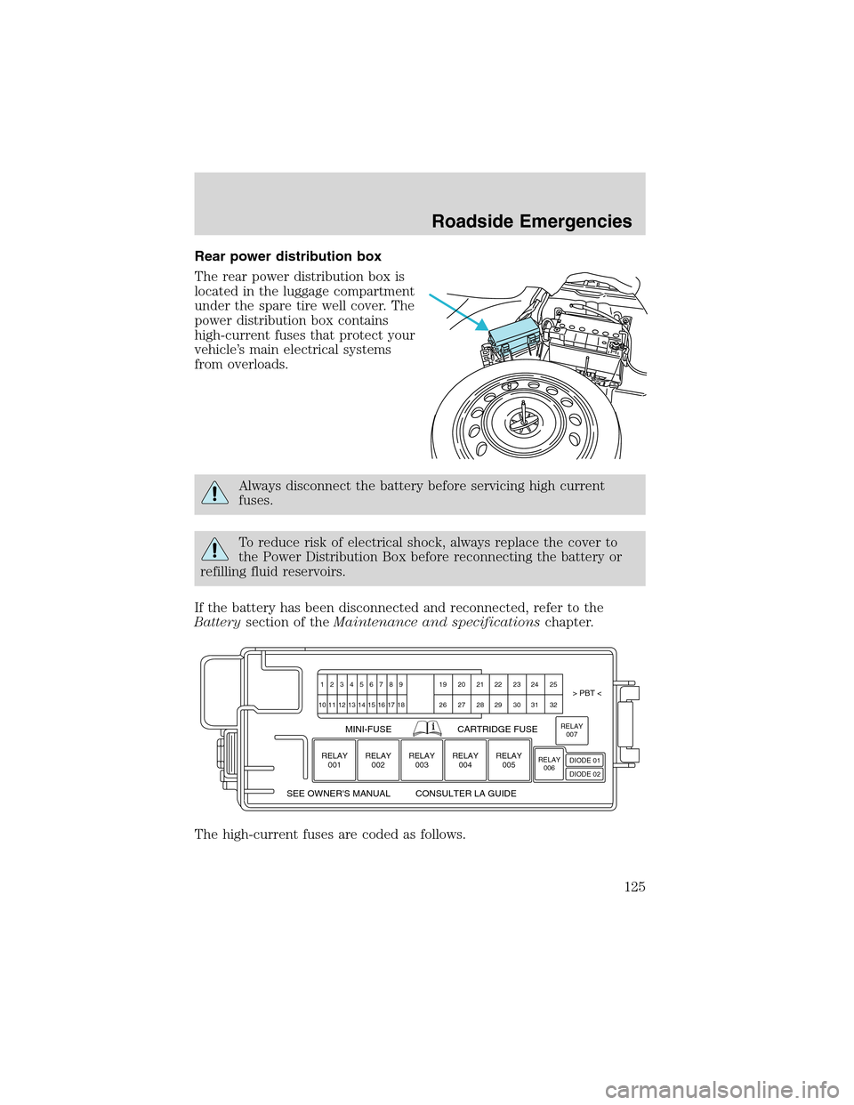
Rear power distribution box
The rear power distribution box is
located in the luggage compartment
under the spare tire well cover. The
power distribution box contains
high-current fuses that protect your
vehicle’s main electrical systems
from overloads.
Always disconnect the battery before servicing high current
fuses.
To reduce risk of electrical shock, always replace the cover to
the Power Distribution Box before reconnecting the battery or
refilling fluid reservoirs.
If the battery has been disconnected and reconnected, refer to the
Batterysection of theMaintenance and specificationschapter.
The high-current fuses are coded as follows.
123456789 19 20 21 22 23 24 25> PBT <
MINI-FUSE
SEE OWNER'S MANUAL CONSULTER LA GUIDECARTRIDGE FUSE
26 27 28 29 30 31 32 10 11
RELAY
001
12 13 14 15 16 17 18
RELAY
002RELAY
003RELAY
004RELAY
005RELAY
006RELAY
007
DIODE 01
DIODE 02
Roadside Emergencies
125
Page 132 of 200
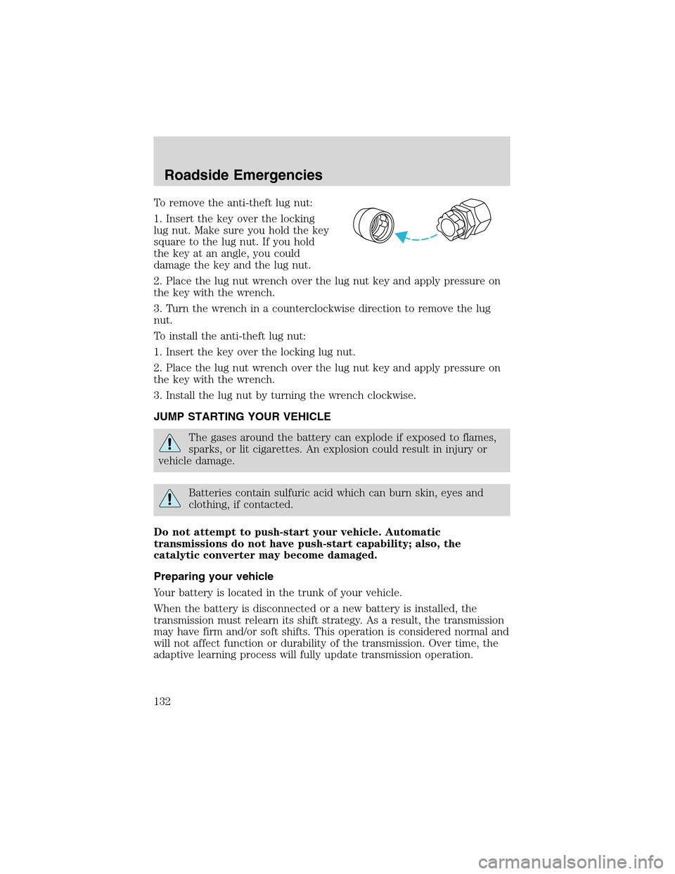
To remove the anti-theft lug nut:
1. Insert the key over the locking
lug nut. Make sure you hold the key
square to the lug nut. If you hold
the key at an angle, you could
damage the key and the lug nut.
2. Place the lug nut wrench over the lug nut key and apply pressure on
the key with the wrench.
3. Turn the wrench in a counterclockwise direction to remove the lug
nut.
To install the anti-theft lug nut:
1. Insert the key over the locking lug nut.
2. Place the lug nut wrench over the lug nut key and apply pressure on
the key with the wrench.
3. Install the lug nut by turning the wrench clockwise.
JUMP STARTING YOUR VEHICLE
The gases around the battery can explode if exposed to flames,
sparks, or lit cigarettes. An explosion could result in injury or
vehicle damage.
Batteries contain sulfuric acid which can burn skin, eyes and
clothing, if contacted.
Do not attempt to push-start your vehicle. Automatic
transmissions do not have push-start capability; also, the
catalytic converter may become damaged.
Preparing your vehicle
Your battery is located in the trunk of your vehicle.
When the battery is disconnected or a new battery is installed, the
transmission must relearn its shift strategy. As a result, the transmission
may have firm and/or soft shifts. This operation is considered normal and
will not affect function or durability of the transmission. Over time, the
adaptive learning process will fully update transmission operation.
Roadside Emergencies
132
Page 133 of 200
1.Useonly a 12–volt supply to start your vehicle.
2. Do not disconnect the battery of your disabled vehicle as this could
damage the vehicle’s electrical system. Keep the battery vent hose
attached at all times.
3. Park the booster vehicle close to the trunk of your disabled vehicle
making sure the two vehiclesdo nottouch. Set the parking brake on
both vehicles and stay clear of the engine cooling fan and other moving
parts.
4. Check all battery terminals and remove any excessive corrosion before
you attach the battery cables. Ensure the vent caps are tight and level.
5. Turn the heater fan on in both vehicles to protect any electrical
surges. Turn all other accessories off.
Connecting the jumper cables
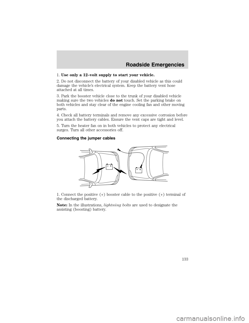
1. Connect the positive (+) booster cable to the positive (+) terminal of
the discharged battery.
Note:In the illustrations,lightning boltsare used to designate the
assisting (boosting) battery.
+–+–
Roadside Emergencies
133
Page 134 of 200
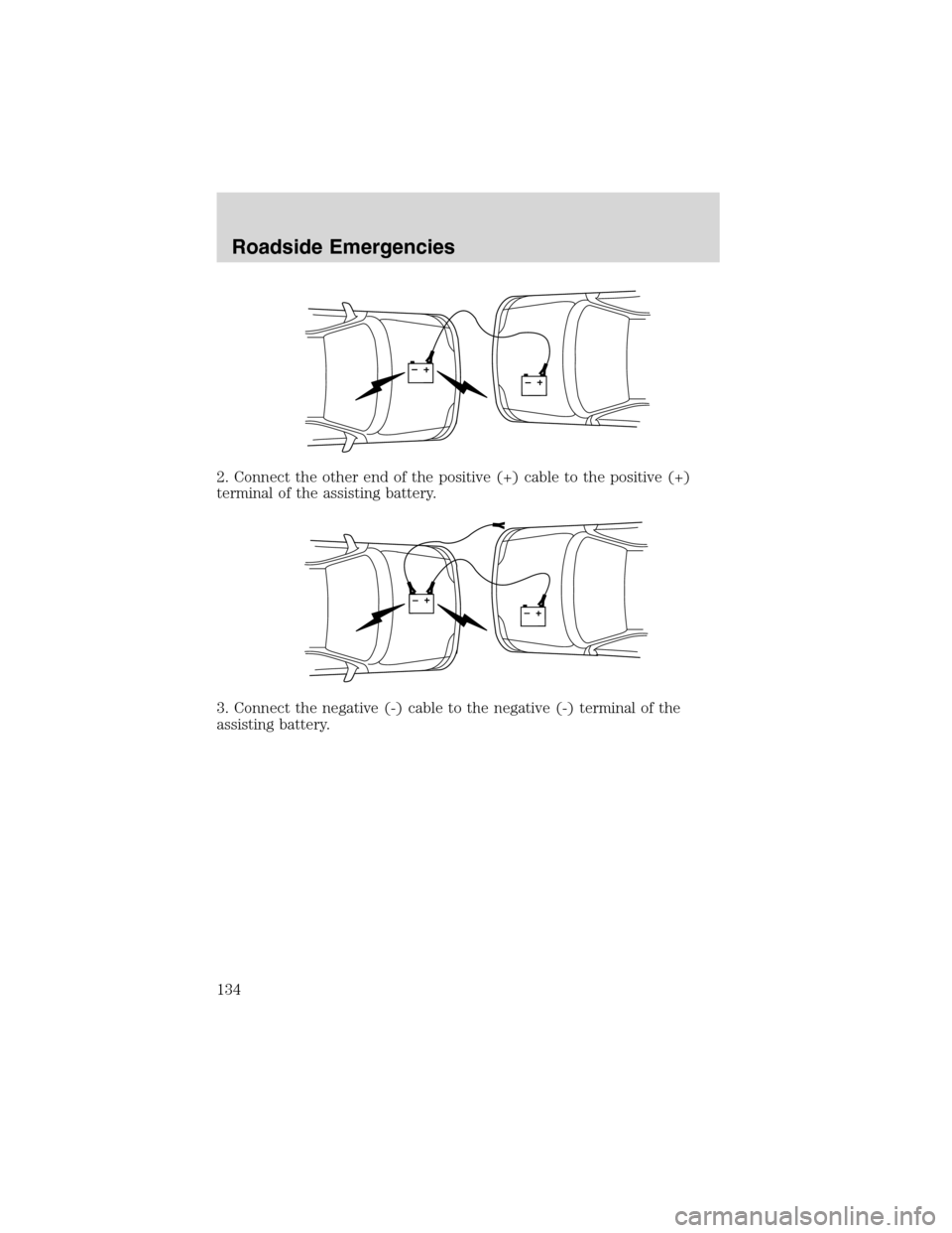
2.Connect the other end of the positive (+) cable to the positive (+)
terminal of the assisting battery.
3. Connect the negative (-) cable to the negative (-) terminal of the
assisting battery.
+–+–
+–+–
Roadside Emergencies
134
Page 135 of 200
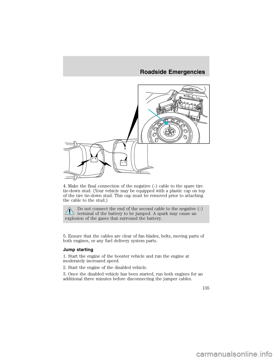
4. Make the final connection of the negative (-) cable to the spare tire
tie-down stud. (Your vehicle may be equipped with a plastic cap on top
of the tire tie-down stud. This cap must be removed prior to attaching
the cable to the stud.)
Do not connect the end of the second cable to the negative (-)
terminal of the battery to be jumped. A spark may cause an
explosion of the gases that surround the battery.
5. Ensure that the cables are clear of fan blades, belts, moving parts of
both engines, or any fuel delivery system parts.
Jump starting
1. Start the engine of the booster vehicle and run the engine at
moderately increased speed.
2. Start the engine of the disabled vehicle.
3. Once the disabled vehicle has been started, run both engines for an
additional three minutes before disconnecting the jumper cables.
+–+–
Roadside Emergencies
135
Page 136 of 200
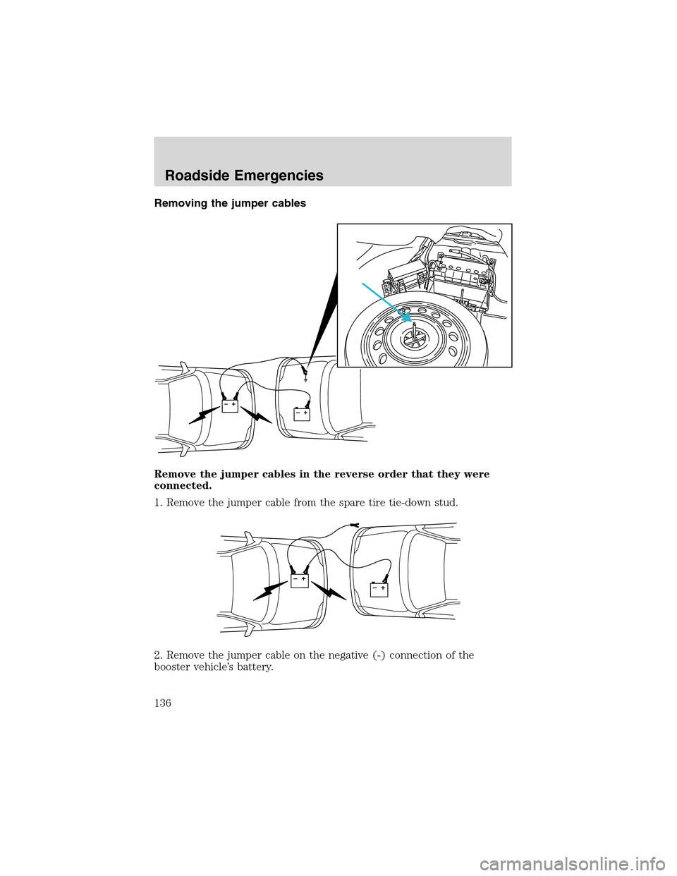
Removing the jumper cables
Remove the jumper cables in the reverse order that they were
connected.
1. Remove the jumper cable from the spare tire tie-down stud.
2. Remove the jumper cable on the negative (-) connection of the
booster vehicle’s battery.
+–+–
+–+–
Roadside Emergencies
136