wheel FORD THUNDERBIRD 2005 11.G Owners Manual
[x] Cancel search | Manufacturer: FORD, Model Year: 2005, Model line: THUNDERBIRD, Model: FORD THUNDERBIRD 2005 11.GPages: 224, PDF Size: 1.91 MB
Page 1 of 224
Introduction 4
Instrument Cluster 10
Warning and control lights 10
Gauges 14
Entertainment Systems 16
AM/FM stereo with in-dash six CD 16
Climate Controls 22
Electronic automatic temperature control 22
Rear window defroster 25
Lights 27
Headlamps 27
Turn signal control 30
Bulb replacement 31
Driver Controls 38
Windshield wiper/washer control 38
Steering wheel adjustment 39
Power windows 40
Mirrors 41
Speed control 42
Locks and Security 62
Keys 62
Locks 62
Anti-theft system 70
Seating and Safety Restraints 74
Seating 74
Safety restraints 77
Air bags 87
Child restraints 97
Table of Contents
1
REVIEW COPY
2005 Thunderbird(tbr), Owners Guide (post-2002-fmt)(own2002),
Market:USA_English(fus)
Table of Contents
Page 2 of 224
Tires, Wheels and Loading 109
Tire Information 110
Changing tires 114
Lug Nut Torque 120
Vehicle loading 130
Trailer towing 134
Recreational towing 135
Driving 136
Starting 136
Brakes 139
Traction control/AdvanceTrac 141
Transmission operation 143
Roadside Emergencies 149
Getting roadside assistance 149
Hazard flasher switch 150
Fuel pump shut-off switch 150
Fuses and relays 151
Jump starting 160
Wrecker towing 166
Customer Assistance 167
Reporting safety defects (U.S. only) 175
Cleaning 176
Table of Contents
2
REVIEW COPY
2005 Thunderbird(tbr), Owners Guide (post-2002-fmt)(own2002),
Market:USA_English(fus)
Page 6 of 224
SPECIAL NOTICES
Emission warranty
The New Vehicle Limited Warranty includes Bumper-to-Bumper
Coverage, Safety Restraint Coverage, Corrosion Coverage, and 6.0L
Power Stroke Diesel Engine Coverage. In addition, your vehicle is eligible
for Emissions Defect and Emissions Performance Warranties. For a
detailed description of what is covered and what is not covered, refer to
theWarranty Guidethat is provided to you along with your Owner’s
Guide.
Service Data Recording
Service data recorders in your vehicle are capable of collecting and
storing diagnostic information about your vehicle. This potentially
includes information about the performance or status of various systems
and modules in the vehicle, such as engine, throttle, steering or brake
systems. In order to properly diagnose and service your vehicle, Ford
Motor Company, Ford of Canada, and service and repair facilities may
access vehicle diagnostic information through a direct connection to your
vehicle when diagnosing or servicing your vehicle.
Event Data Recording
Other modules in your vehicle—event data recorders—are capable of
collecting and storing data during a crash or near crash event. The
recorded information may assist in the investigation of such an event.
The modules may record information about both the vehicle and the
occupants, potentially including information such as:
•how various systems in your vehicle were operating;
•whether or not the driver and passenger seatbelts were buckled;
•how far (if at all) the driver was depressing the accelerator and/or the
brake pedal;
•how fast the vehicle was traveling; and
•where the driver was positioning the steering wheel.
REVIEW COPY
2005 Thunderbird(tbr), Owners Guide (post-2002-fmt)(own2002),
Market:USA_English(fus)
Introduction
6
Page 39 of 224
POWER TILT/TELESCOPE STEERING COLUMN
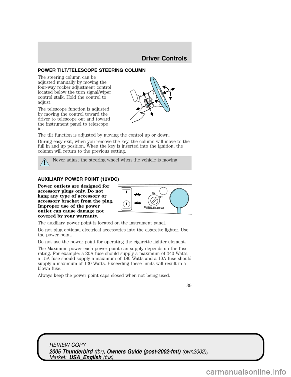
The steering column can be
adjusted manually by moving the
four-way rocker adjustment control
located below the turn signal/wiper
control stalk. Hold the control to
adjust.
The telescope function is adjusted
by moving the control toward the
driver to telescope out and toward
the instrument panel to telescope
in.
The tilt function is adjusted by moving the control up or down.
During easy exit, when you remove the key, the column will move to the
full in and up position. When the key is inserted into the ignition, the
column will return to the previous setting.
Never adjust the steering wheel when the vehicle is moving.
AUXILIARY POWER POINT (12VDC)
Power outlets are designed for
accessory plugs only. Do not
hang any type of accessory or
accessory bracket from the plug.
Improper use of the power
outlet can cause damage not
covered by your warranty.
The auxiliary power point is located on the instrument panel.
Do not plug optional electrical accessories into the cigarette lighter. Use
the power point.
Do not use the power point for operating the cigarette lighter element.
The Maximum power each power point can supply depends on the fuse
rating. For example: a 20A fuse should supply a maximum of 240 Watts,
a 15A fuse should supply a maximum of 180 Watts and a 10A fuse should
supply a maximum of 120 Watts. Exceeding these limits will result in a
blown fuse.
Always keep the power point caps closed when not being used.
PASSENGER AIRBAG
OFF ON
REVIEW COPY
2005 Thunderbird(tbr), Owners Guide (post-2002-fmt)(own2002),
Market:USA_English(fus)
Driver Controls
39
Page 43 of 224
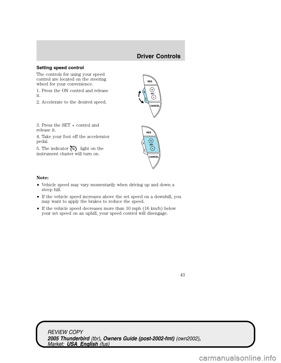
Setting speed control
The controls for using your speed
control are located on the steering
wheel for your convenience.
1. Press the ON control and release
it.
2. Accelerate to the desired speed.
3. Press the SET + control and
release it.
4. Take your foot off the accelerator
pedal.
5. The indicator
light on the
instrument cluster will turn on.
Note:
•Vehicle speed may vary momentarily when driving up and down a
steep hill.
•If the vehicle speed increases above the set speed on a downhill, you
may want to apply the brakes to reduce the speed.
•If the vehicle speed decreases more than 10 mph (16 km/h) below
your set speed on an uphill, your speed control will disengage.
REVIEW COPY
2005 Thunderbird(tbr), Owners Guide (post-2002-fmt)(own2002),
Market:USA_English(fus)
Driver Controls
43
Page 45 of 224
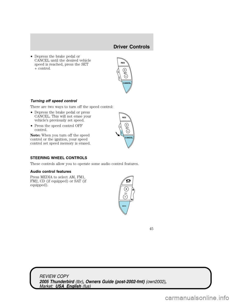
•Depress the brake pedal or
CANCEL until the desired vehicle
speed is reached, press the SET
+ control.
Turning off speed control
There are two ways to turn off the speed control:
•Depress the brake pedal or press
CANCEL. This will not erase your
vehicle’s previously set speed.
•Press the speed control OFF
control.
Note:When you turn off the speed
control or the ignition, your speed
control set speed memory is erased.
STEERING WHEEL CONTROLS
These controls allow you to operate some audio control features.
Audio control features
Press MEDIA to select AM, FM1,
FM2, CD (if equipped) or SAT (if
equipped).
O
N
O
F
F
RES
SET
CANCEL
MUTE
VOL
MEDIA
REVIEW COPY
2005 Thunderbird(tbr), Owners Guide (post-2002-fmt)(own2002),
Market:USA_English(fus)
Driver Controls
45
Page 55 of 224
Installing the removable top
The front screw fittings must be checked to see that they are
firmly seated after driving a distance of approximately 50 to
60 km (30 to 40 miles).
The removable top does not have the same crush resistance as
an integrated steel roof in case of collision or rollover.
The removable top is not, under any circumstances, to be used
to carry or support external loads.
Movement of the removable top requires at least two people.
The removable top weighs approximately 38 kg (84 lb). Also,
due to its shape, the weight is biased to the rear of the removable top.
Your vehicle must be turned OFF and placed in PARK on a level
surface prior to installing or removing the top.
Open the doors, lower the windows, and clean the area where the
removable top mounts on the body. Before installing the removable top,
unsnap and properly store the convertible top boot. Refer toInstallation
of the bootin theConvertiblesection. Also, thoroughly dry the
convertible top and then lower.
Note:Before installing the removable top, apply the protective tape to
the rear deck of the vehicle, refer to theQuick Reference Guidefor
instructions.
1. Remove the protective cover from the top. Using a mild detergent,
clean the weather-strips on the top before installing it on the vehicle.
2. Ensure that the removable top levers are rotated rearward to the fully
open position. Lock the wheels on the storage cart, and with the help of
at least another person remove the top from the cart.
REVIEW COPY
2005 Thunderbird(tbr), Owners Guide (post-2002-fmt)(own2002),
Market:USA_English(fus)
Driver Controls
55
Page 59 of 224
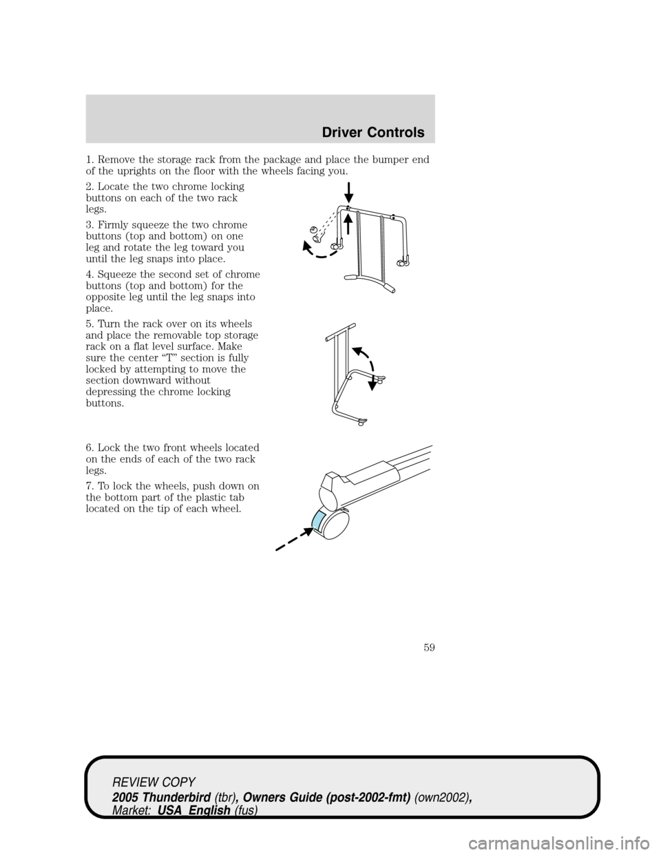
1. Remove the storage rack from the package and place the bumper end
of the uprights on the floor with the wheels facing you.
2. Locate the two chrome locking
buttons on each of the two rack
legs.
3. Firmly squeeze the two chrome
buttons (top and bottom) on one
leg and rotate the leg toward you
until the leg snaps into place.
4. Squeeze the second set of chrome
buttons (top and bottom) for the
opposite leg until the leg snaps into
place.
5. Turn the rack over on its wheels
and place the removable top storage
rack on a flat level surface. Make
sure the center“T”section is fully
locked by attempting to move the
section downward without
depressing the chrome locking
buttons.
6. Lock the two front wheels located
on the ends of each of the two rack
legs.
7. To lock the wheels, push down on
the bottom part of the plastic tab
located on the tip of each wheel.
REVIEW COPY
2005 Thunderbird(tbr), Owners Guide (post-2002-fmt)(own2002),
Market:USA_English(fus)
Driver Controls
59
Page 60 of 224
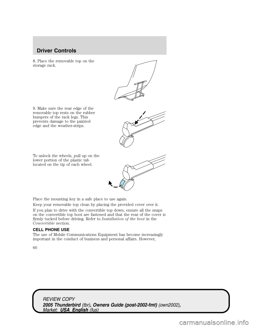
8. Place the removable top on the
storage rack.
9. Make sure the rear edge of the
removable top rests on the rubber
bumpers of the rack legs. This
prevents damage to the painted
edge and the weather-strips.
To unlock the wheels, pull up on the
lower portion of the plastic tab
located on the tip of each wheel.
Place the mounting key in a safe place to use again.
Keep your removable top clean by placing the provided cover over it.
If you plan to drive with the convertible top down, ensure all the snaps
on the convertible top boot are fastened and that the rear of the cover is
firmly tucked before driving. Refer toInstallation of the bootin the
Convertiblesection.
CELL PHONE USE
The use of Mobile Communications Equipment has become increasingly
important in the conduct of business and personal affairs. However,
REVIEW COPY
2005 Thunderbird(tbr), Owners Guide (post-2002-fmt)(own2002),
Market:USA_English(fus)
Driver Controls
60
Page 109 of 224
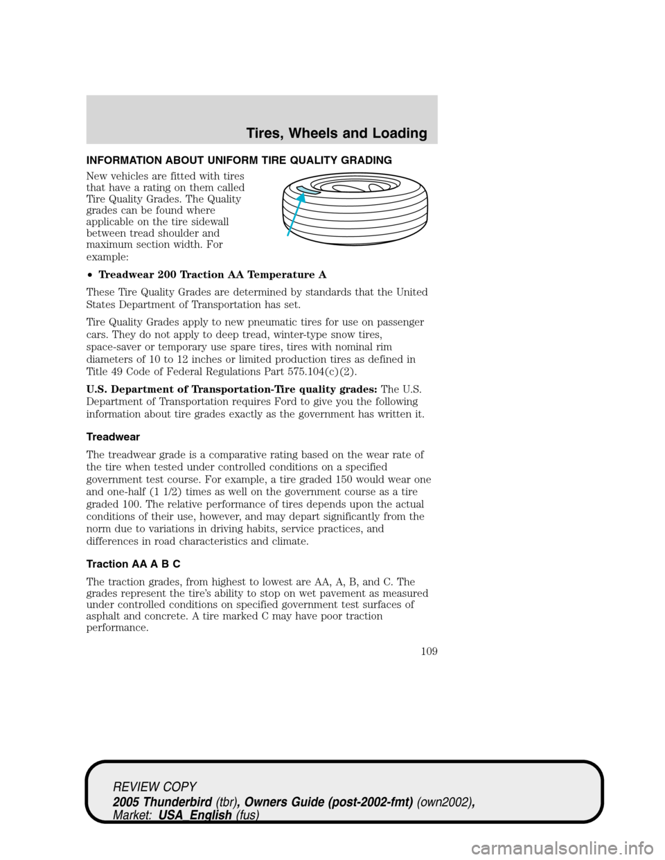
INFORMATION ABOUT UNIFORM TIRE QUALITY GRADING
New vehicles are fitted with tires
that have a rating on them called
Tire Quality Grades. The Quality
grades can be found where
applicable on the tire sidewall
between tread shoulder and
maximum section width. For
example:
•Treadwear 200 Traction AA Temperature A
These Tire Quality Grades are determined by standards that the United
States Department of Transportation has set.
Tire Quality Grades apply to new pneumatic tires for use on passenger
cars. They do not apply to deep tread, winter-type snow tires,
space-saver or temporary use spare tires, tires with nominal rim
diameters of 10 to 12 inches or limited production tires as defined in
Title 49 Code of Federal Regulations Part 575.104(c)(2).
U.S. Department of Transportation-Tire quality grades:The U.S.
Department of Transportation requires Ford to give you the following
information about tire grades exactly as the government has written it.
Treadwear
The treadwear grade is a comparative rating based on the wear rate of
the tire when tested under controlled conditions on a specified
government test course. For example, a tire graded 150 would wear one
and one-half (1 1/2) times as well on the government course as a tire
graded 100. The relative performance of tires depends upon the actual
conditions of their use, however, and may depart significantly from the
norm due to variations in driving habits, service practices, and
differences in road characteristics and climate.
Traction AA A B C
The traction grades, from highest to lowest are AA, A, B, and C. The
grades represent the tire’s ability to stop on wet pavement as measured
under controlled conditions on specified government test surfaces of
asphalt and concrete. A tire marked C may have poor traction
performance.
REVIEW COPY
2005 Thunderbird(tbr), Owners Guide (post-2002-fmt)(own2002),
Market:USA_English(fus)
Tires, Wheels and Loading
Tires, Wheels and Loading
109