check oil FORD TRANSIT 2006 7.G Body And Equipment Mounting Section Manual
[x] Cancel search | Manufacturer: FORD, Model Year: 2006, Model line: TRANSIT, Model: FORD TRANSIT 2006 7.GPages: 234, PDF Size: 33.19 MB
Page 62 of 234

2.6 Brake System
2.6.1 General
The Brake System must be fully functional when
the vehicle conversion is completed. The vehicle
brake operating modes must be checked,
including warning system and parking brakes.
Brakes are certified to 71/320EEC and ECE R13
requirements as amended.
WARNING: Do not restrict the airflow
and cooling to the brake system
CAUTION: Spoilers and wheel covers
must not affect the brake cooling
performance.
NOTE: Do not obstruct the view of the brake
fluid reservoir level
NOTE: The donor vehicle brake fluid reservoir is
translucent so that it is possible to check the level
of fluid without opening the reservoir which will
reduce the risk of contamination.
The brake fluid reservoir must remain accessible
for servicing and for adding brake fluid.
2.6.2 Kerb Mass Data
NOTE: For further information please contact
your local National Sales Company representative,
or Local Ford Dealer. If they are unable to help
you then please contact the Vehicle Converter
Advisory Service at [email protected].
2.6.3 Brake Hoses General
CAUTION: Make sure that the front
and rear brake hoses are not
twisted and are correctly located
away from body and chassis
components.
Front and rear brake hoses must not rub, chafe
or rest on body or chassis components. There
must be clearance under all operating conditions,
between full compression and extension and full
lock to lock.
Brake lines must not be used to support or
secure any other component.
FordTransit 2006.5 (April 2006–)
Date of Publication: 12/2006
2 Chassis
62
Page 155 of 234

However, it is possible to add an additional lock(s)
– see also the section covering the ‘third button
on key fob’ – but only by utilizing relays (the
electric locks are operated by surface mounted
relays in the Central Junction Box – these are
only capable of powering one lock each, in
addition to which the output of these devices is
current-sensed to check it is within minimum and
maximum limits: I) to verify operation, and ii) as
part of the security system). For camper vehicles,
the Central Junction Box is configured for a
chassis cab vehicle.
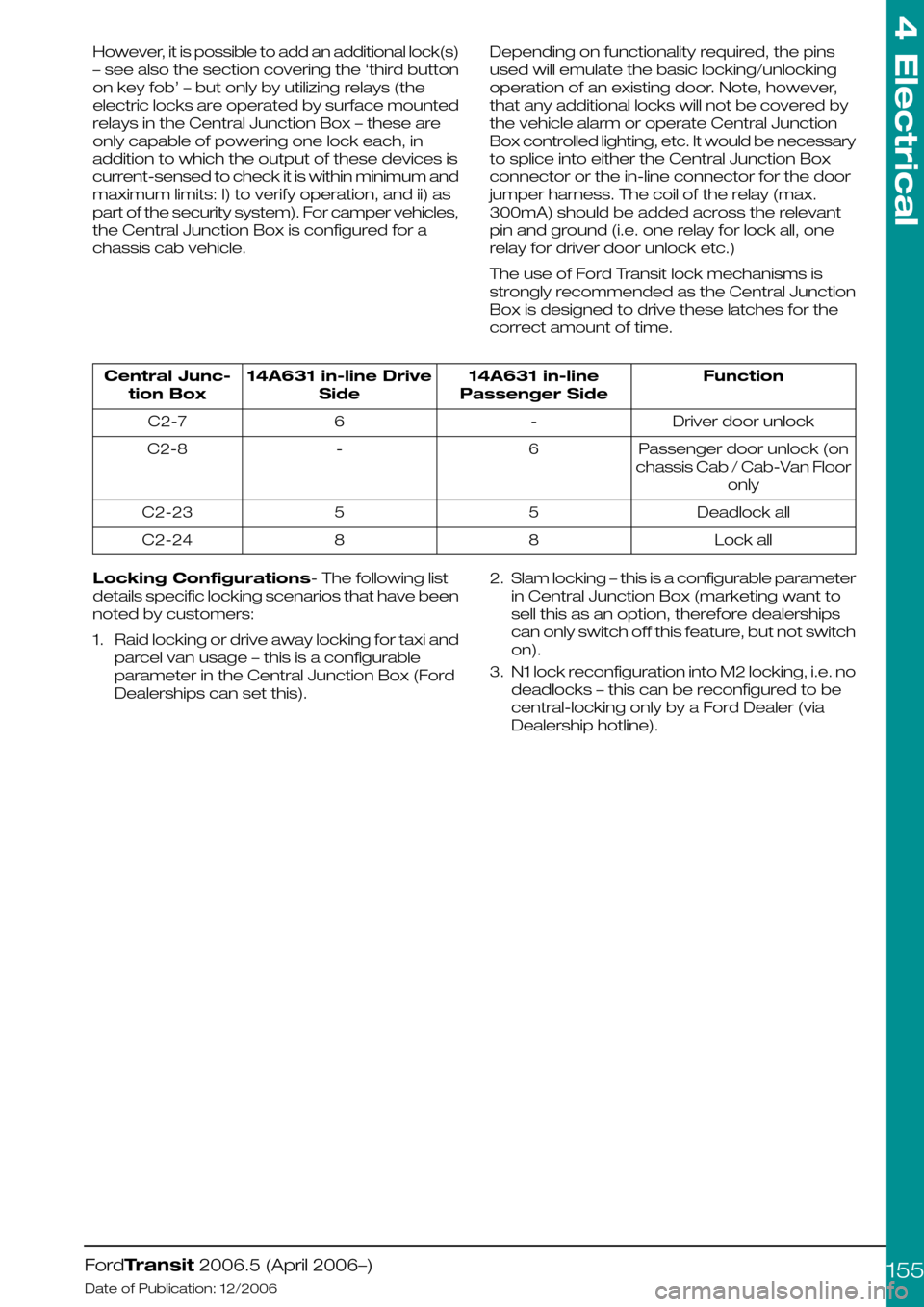
Depending on functionality required, the pins
used will emulate the basic locking/unlocking
operation of an existing door. Note, however,
that any additional locks will not be covered by
the vehicle alarm or operate Central Junction
Box controlled lighting, etc. It would be necessary
to splice into either the Central Junction Box
connector or the in-line connector for the door
jumper harness. The coil of the relay (max.
300mA) should be added across the relevant
pin and ground (i.e. one relay for lock all, one
relay for driver door unlock etc.)
The use of Ford Transit lock mechanisms is
strongly recommended as the Central Junction
Box is designed to drive these latches for the
correct amount of time.
Function14A631 in-line
Passenger Side
14A631 in-line Drive
Side
Central Junc-
tion Box
Driver door unlock-6C2-7
Passenger door unlock (on
chassis Cab / Cab-Van Floor
only
6-C2-8
Deadlock all55C2-23
Lock all88C2-24
Locking Configurations- The following list
details specific locking scenarios that have been
noted by customers:
1.Raid locking or drive away locking for taxi and
parcel van usage – this is a configurable
parameter in the Central Junction Box (Ford
Dealerships can set this).
2.Slam locking – this is a configurable parameter
in Central Junction Box (marketing want to
sell this as an option, therefore dealerships
can only switch off this feature, but not switch
on).
3.N1 lock reconfiguration into M2 locking, i.e. no
deadlocks – this can be reconfigured to be
central-locking only by a Ford Dealer (via
Dealership hotline).
FordTransit 2006.5 (April 2006–)
Date of Publication: 12/2006
4 Electrical
155