heater FORD TRANSIT 2006 7.G Body And Equipment Mounting Section Manual
[x] Cancel search | Manufacturer: FORD, Model Year: 2006, Model line: TRANSIT, Model: FORD TRANSIT 2006 7.GPages: 234, PDF Size: 33.19 MB
Page 3 of 234
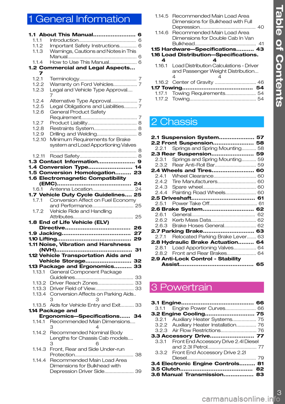
1 General Information
1.1About This Manual........................6
1.1.1Introduction...........................................6
1.1.2Important Safety Instructions.............6
1.1.3Warnings, Cautions and Notes in This
Manual....................................................6
1.1.4How to Use This Manual.....................6
1.2Commercial and Legal Aspects...
7
1.2.1Terminology...........................................7
1.2.2Warranty on Ford Vehicles..................7
1.2.3Legal and Vehicle Type Approval....
7
1.2.4Alternative Type Approval....................7
1.2.5Legal Obligations and Liabilities..........7
1.2.6General Product Safety
Requirement..........................................7
1.2.7Product Liability.....................................8
1.2.8Restraints System................................8
1.2.9Drilling and Welding..............................8
1.2.10Minimum Requirements for Brake
system and Load Apportioning Valves
.................................................................8
1.2.11Road Safety...........................................8
1.3Contact Information.....................9
1.4Conversion Type.........................14
1.5Conversion Homologation.........23
1.6Electromagnetic Compatibility
(EMC)..........................................24
1.6.1Antenna Location...............................24
1.7Vehicle Duty Cycle Guidelines....25
1.7.1Conversion Affect on Fuel Economy
and Performance...............................25
1.7.2Vehicle Ride and Handling
Attributes.............................................25
1.8End of Life Vehicle (ELV)
Directive.....................................26
1.9Jacking.......................................27
1.10Lifting..........................................29
1.11Noise, Vibration and Harshness
(NVH)...........................................31
1.12Vehicle Transportation Aids and
Vehicle Storage..........................32
1.13Package and Ergonomics..........33
1.13.1General Component Package
Guidelines............................................33
1.13.2Driver Reach Zones...........................33
1.13.3Driver Field of View.............................33
1.13.4Conversion Affects on Parking Aids..
33
1.13.5Aids for Vehicle Entry and Exit..........33
1.14Package and
Ergonomics—Specifications......34
1.14.1Recommended Main Dimensions....
34
1.14.2Recommended Nominal Body
Lengths for Chassis Cab models....
36
1.14.3Front, Rear and Side Under-run
Protection............................................38
1.14.4Recommended Main Load Area
Dimensions for Bulkhead with
Depression Driver Side......................39
1.14.5Recommended Main Load Area
Dimensions for Bulkhead with Full
Depression..........................................40
1.14.6Recommended Main Load Area
Dimensions for Double Cab In Van
Bulkhead..............................................41
1.15Hardware—Specifications..........43
1.16Load Distribution—Specifications.
44
1.16.1Load Distribution Calculations - Driver
and Passenger Weight Distribution...
44
1.16.2Center of Gravity ...............................46
1.17Towing........................................54
1.17.1Towing Requirements.......................54
1.17.2Towing..................................................54
2 Chassis
2.1Suspension System....................57
2.2Front Suspension.......................58
2.2.1Springs and Spring Mounting...........58
2.3Rear Suspension........................59
2.3.1Springs and Spring Mounting...........59
2.3.2Rear Anti-Roll Bar...............................59
2.4Wheels and Tires........................60
2.4.1Wheel Clearance................................60
2.4.2Tire Manufacturers.............................60
2.4.3Spare wheel........................................60
2.4.4Painting Road Wheels.......................60
2.5Driveshaft....................................61
2.5.1Power Take Off....................................61
2.6Brake System.............................62
2.6.1General................................................62
2.6.2Kerb Mass Data..................................62
2.6.3Brake Hoses General........................62
2.7Parking Brake.............................63
2.7.1Relocated Parking Brake Lever.......63
2.8Hydraulic Brake Actuation.........64
2.8.1Load Apportioning Valves.................64
2.8.2Front and Rear Brakes......................64
2.9Anti-Lock Control - Stability
Assist..........................................65
3 Powertrain
3.1Engine.........................................66
3.1.1Engine Power Curves.......................66
3.2Engine Cooling............................75
3.2.1Auxiliary Heater Systems..................75
3.2.2Auxiliary Heater Installation...............76
3.2.3Air Flow Restrictions...........................76
3.3Accessory Drive.........................77
3.3.1Front End Accessory Drive 2.4l Diesel
and 2.3l Petrol.....................................77
3.3.2Front End Accessory Drive 2.2l
Diesel....................................................79
3.4Electronic Engine Controls.........81
3.5Clutch.........................................82
3.6Manual Transmission.................83
Table of Contents
3
Page 75 of 234
3.2 Engine Cooling
3.2.1 Auxiliary Heater Systems
WARNINGS:
Ford coolant additives are
necessary for the complete function
of the system. Only use ford
approved or equivalent specification
component, to withstand any
detrimental effects on the materials.
Do not mount components in front
of the grille or in an area of air flow
around the engine, which could
affect the engine cooling.
CAUTIONS:
Only make connections into the
heater hose between the front cab
heater and water pump return inlet.
Do not exceed the vehicle's original
coolant volume by more than 10%
Only use the manufactures
recommended (or equivalent
specification) coolant
additives/anti-freeze. Do not mix
coolant types.
•Coolant flow to cab heater must have priority
over flow to auxiliary heater or hand wash
facility.
•Coolant tube routing must be below the base
of the degas bottle.
•Use aluminum or plastic tee junction with
swaged or beaded ends to prevent hose blow
off. Reconnect original coolant tube as shown
in view E74570 (in this section) with standard
Ford water hose clip or suitable equivalent
specification clip. Ensure interference fit
between hose and 'T' joint.
•Tube routing must be secured to the body
structure or suitable brackets avoiding
electrical components or wires, hot or moving
parts and brake or fuel system components
•Hose must be heat sleeved with appropriate
material if within 100mm of exhaust
components (for example, manifold or
exhaust gas recirculating).
•The vertical clearance between the critical
cooling components (radiator, fan shroud and
radiator brackets) and both the hood inner
and outer (assembly) panels at design position
shall not be less than 15mm.
•There shall be a minimum clearance of 7mm
between the engine assembly and flexible
components (for example, hoses or wiring
harnesses) affixed to front end sheet metal
hardware, under a maximum engine torque
roll condition.
NOTE: For further information please contact
your local National Sales Company
representative, or Local Ford Dealer. If they are
unable to help you then please contact the
Vehicle Converter Advisory service at
[email protected].
FordTransit 2006.5 (April 2006–)
Date of Publication: 12/2006
3 Powertrain
75
Page 76 of 234
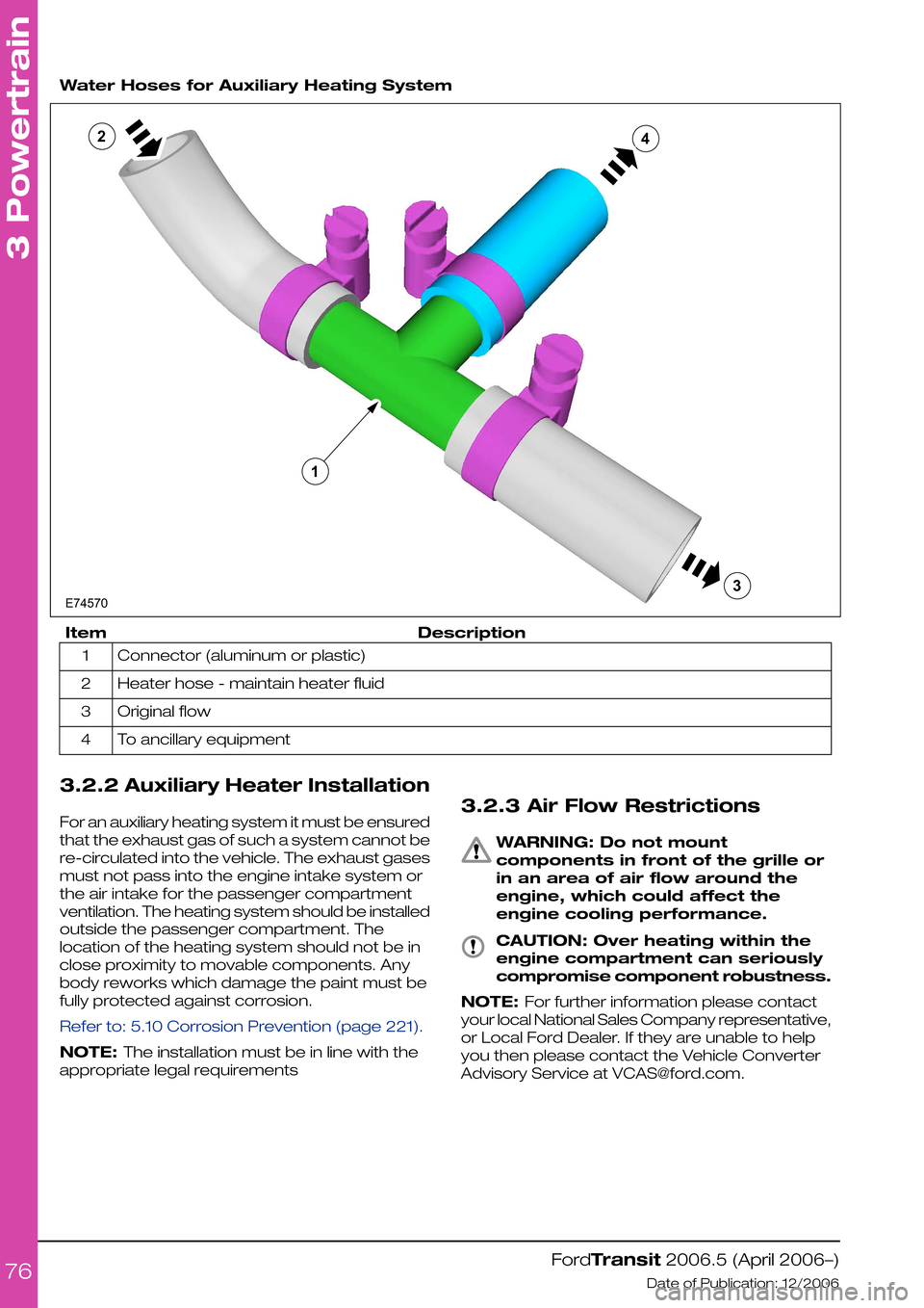
Water Hoses for Auxiliary Heating System
DescriptionItem
Connector (aluminum or plastic)1
Heater hose - maintain heater fluid2
Original flow3
To ancillary equipment4
3.2.2 Auxiliary Heater Installation
For an auxiliary heating system it must be ensured
that the exhaust gas of such a system cannot be
re-circulated into the vehicle. The exhaust gases
must not pass into the engine intake system or
the air intake for the passenger compartment
ventilation. The heating system should be installed
outside the passenger compartment. The
location of the heating system should not be in
close proximity to movable components. Any
body reworks which damage the paint must be
fully protected against corrosion.
Refer to: 5.10 Corrosion Prevention (page 221).
NOTE: The installation must be in line with the
appropriate legal requirements
3.2.3 Air Flow Restrictions
WARNING: Do not mount
components in front of the grille or
in an area of air flow around the
engine, which could affect the
engine cooling performance.
CAUTION: Over heating within the
engine compartment can seriously
compromise component robustness.
NOTE: For further information please contact
your local National Sales Company representative,
or Local Ford Dealer. If they are unable to help
you then please contact the Vehicle Converter
Advisory Service at [email protected].
FordTransit 2006.5 (April 2006–)
Date of Publication: 12/2006
3 Powertrain
76E745701234
Page 88 of 234
3.8 Fuel System
WARNINGS:
Do not cut into the original fuel
supply lines
Make sure that the modified vehicle
complies with all relevant legal
requirements.
For auxiliary applications requiring a fuel supply,
it is advisable to use the auxiliary fuel supply port
as shown in the figure below.
•The auxiliary fuel supply port is mounted on
the top of the fuel sender unit located on the
top of the fuel tank, for applications such as
an auxiliary heater or fuel fired hand wash
facility.
•Ensure that a suitable fuel shut-off is fitted in
any unique system.
•Refit the Ford hose assembly from the fuel
pump to the fuel line.
•The tube and/or line must be routed
independently and secured to the body
structure or to suitable brackets.
CAUTION: Make sure that sufficient
clearance is maintained for all
driving conditions to all hot and
moving components.
NOTE: Do not fasten anything to existing
electrical components or wires
FordTransit 2006.5 (April 2006–)
Date of Publication: 12/2006
3 Powertrain
88
Page 106 of 234
4.5 Climate Control System
WARNING: Do not use propylene
glycol based coolant
•Never secure hoses or tubes to the
transmission fill or dip stick or to any fuel
system or brake component
•Do not route heater or refrigerant lines near or
directly over any exhaust system component,
including the exhaust manifolds.
•Avoid routing of hoses in the wheelhouse or
stone kick-up arch. However, if routing is
required in these areas, shield against stone
pecking as appropriate.
•Do not route hoses near sharp edges. Utilize
guards to protect against cutting or chafing.
FordTransit 2006.5 (April 2006–)
Date of Publication: 12/2006
4 Electrical
106
Page 124 of 234
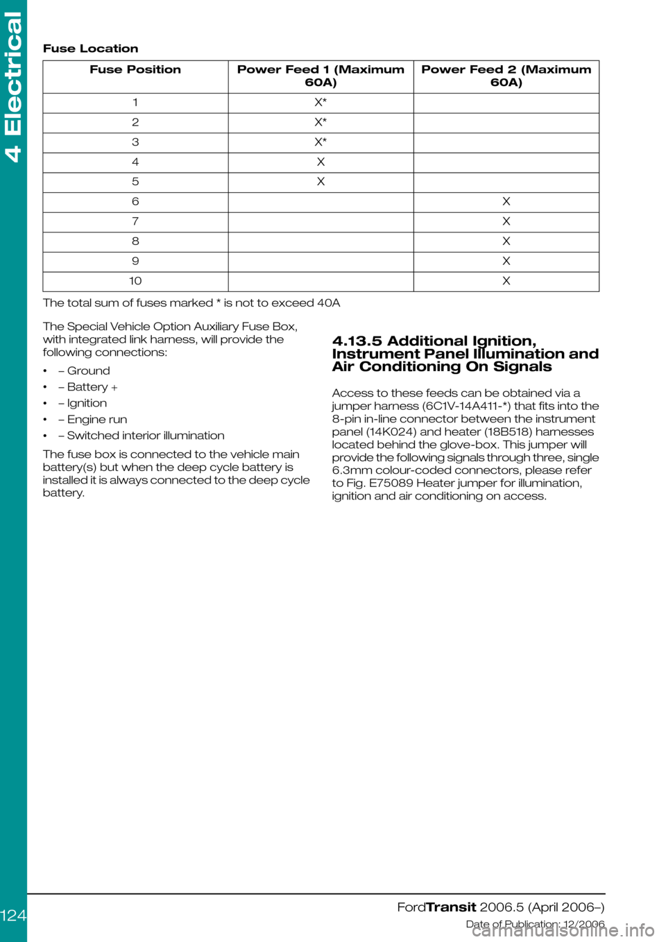
Fuse Location
Power Feed 2 (Maximum
60A)
Power Feed 1 (Maximum
60A)
Fuse Position
X*1
X*2
X*3
X4
X5
X6
X7
X8
X9
X10
The total sum of fuses marked * is not to exceed 40A
The Special Vehicle Option Auxiliary Fuse Box,
with integrated link harness, will provide the
following connections:
•– Ground
•– Battery +
•– Ignition
•– Engine run
•– Switched interior illumination
The fuse box is connected to the vehicle main
battery(s) but when the deep cycle battery is
installed it is always connected to the deep cycle
battery.
4.13.5 Additional Ignition,
Instrument Panel Illumination and
Air Conditioning On Signals
Access to these feeds can be obtained via a
jumper harness (6C1V-14A411-*) that fits into the
8-pin in-line connector between the instrument
panel (14K024) and heater (18B518) harnesses
located behind the glove-box. This jumper will
provide the following signals through three, single
6.3mm colour-coded connectors, please refer
to Fig. E75089 Heater jumper for illumination,
ignition and air conditioning on access.
FordTransit 2006.5 (April 2006–)
Date of Publication: 12/2006
4 Electrical
124
Page 126 of 234

Heater Jumper for Ignition, Instrument Panel Illumination and Air Conditioning On
Signals - Early Installation
DescriptionItem
Ignition, Instrument Panel Illumination and Air Conditioning On Signals1
C4 - Connection to Heating, Ventilation and Air Conditioning Harness (18B518)2
C5 - Connection to Instrument Panel Harness (14K024)3
FordTransit 2006.5 (April 2006–)
Date of Publication: 12/2006
4 Electrical
126E75089123
Page 127 of 234
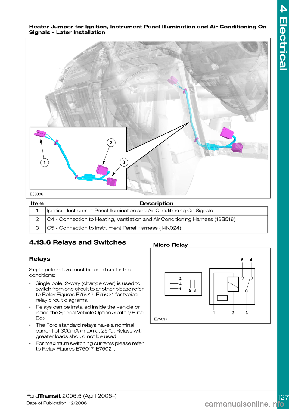
Heater Jumper for Ignition, Instrument Panel Illumination and Air Conditioning On
Signals - Later Installation
DescriptionItem
Ignition, Instrument Panel Illumination and Air Conditioning On Signals1
C4 - Connection to Heating, Ventilation and Air Conditioning Harness (18B518)2
C5 - Connection to Instrument Panel Harness (14K024)3
4.13.6 Relays and Switches
Relays
Single pole relays must be used under the
conditions:
•Single pole, 2-way (change over) is used to
switch from one circuit to another please refer
to Relay Figures E75017-E75021 for typical
relay circuit diagrams.
•Relays can be installed inside the vehicle or
inside the Special Vehicle Option Auxiliary Fuse
Box.
•The Ford standard relays have a nominal
current of 300mA (max) at 25°C. Relays with
greater loads should not be used.
•For maximum switching currents please refer
to Relay Figures E75017-E75021.
Micro Relay
FordTransit 2006.5 (April 2006–)
Date of Publication: 12/2006
4 Electrical
127E88306123 E750171425312354
Page 129 of 234
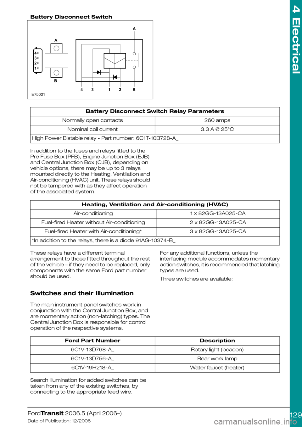
Battery Disconnect Switch
Battery Disconnect Switch Relay Parameters
260 ampsNormally open contacts
3.3 A @ 25°CNominal coil current
High Power Bistable relay - Part number: 6C1T-10B728-A_
In addition to the fuses and relays fitted to the
Pre Fuse Box (PFB), Engine Junction Box (EJB)
and Central Junction Box (CJB), depending on
vehicle options, there may be up to 3 relays
mounted directly to the Heating, Ventilation and
Air-conditioning (HVAC) unit. These relays should
not be tampered with as they affect operation
of the associated system.
Heating, Ventilation and Air-conditioning (HVAC)
1 x 82GG-13A025-CAAir-conditioning
2 x 82GG-13A025-CAFuel-fired Heater without Air-conditioning
3 x 82GG-13A025-CAFuel-fired Heater with Air-conditioning*
*In addition to the relays, there is a diode 91AG-10374-B_
These relays have a different terminal
arrangement to those fitted throughout the rest
of the vehicle – if they need to be replaced, only
components with the same Ford part number
should be used.
Switches and their Illumination
The main instrument panel switches work in
conjunction with the Central Junction Box, and
are momentary action (non-latching) types. The
Central Junction Box is responsible for control
operation of the respective systems.
For any additional functions, unless the
interfacing module accommodates momentary
action switches, it is recommended that latching
types are used.
Three switches are available:
DescriptionFord Part Number
Rotary light (beacon)6C1V-13D768-A_
Rear work lamp6C1V-13D756-A_
Water faucet (heater)6C1V-19H218-A_
Search illumination for added switches can be
taken from any of the existing switches, by
connecting to the appropriate feed wire.
FordTransit 2006.5 (April 2006–)
Date of Publication: 12/2006
4 Electrical
129E750211234AB4312BA
Page 154 of 234
harness that provides roof-mounted rear turn
indicators, powered via relays. This should be
used in conjunction with SVO fusebox.
3.Chassis cab LED rear lamp cluster
replacement recommendations, especially
turn indicator relay implications – see lighting
load table. Generally the use of LED equivalent
lighting systems reduces the electrical load on
the vehicle; however, special care needs to
be taken with respect to any change to or
addition of turn indicator lights. Depending on
the current requirements of the LED(s)
compared to the bulb it is replacing, a ballast
resistor may be required, if not already
integrated into the LED lamp assembly.
Without this, bulb outage detection for turn
indicators will be affected, which is a legal
requirement.
Additional turn indicators must be powered
through relays (max 300mA), driven by existing
turn lights. The maximum load that the Central
Junction Box can drive is 3 x 21W per side (front,
rear and CAT 6 turn indicators); but even if the
vehicle is not fitted with the CAT 6 lights, the feeds
for these should not be used as the Central
Junction Box would need reconfiguring, which
could have safety as well as functional
implications.
4.Special Vehicle Option beacon switch: wiring
locations, circuit diagrams and max amperage
– see Special Vehicle Option fuse box
schematic (max current is 15A); there is
provision for the Special Vehicle Option beacon
switch in an empty switch location on the
instrument panel.
5.Rear loom connector detail location and supply
details for retro-fit loom extension for
example:- when extending a medium wheel
base, long wheel base or extended frame
overhang, what connectors do they use to
make a plug and play loom extension? – for
chassis cab vehicles, there is an Special
Vehicle Option extension loom for rear lamps
(part number 6C1V-14408-A*). There is not, at
present, a similar loom for Van, Bus and
Kombi's, although the appropriate mating
connector is now tooled, so this would be
possible.
Miscellaneous Systems
Handbrake on - Cluster Warning Light -
Unless the vehicle is specified with options that
drive the handbrake warning light (for example
ESP, Australia market), the components making
up this system are not fitted. We do not
recommend installation of this feature as an
aftermarket addition. There are several reasons
for this:
1.Not all circuits carry the requisite wire as a give
away:
•The wires might be part of the main vehicle
harness (14401) even if not used – for example
camper vehicles are normally ordered with
power mirrors, and the wires will be present
as a give-away.
•The seat pedestal harness (14K076), however,
is vehicle specific – if the handbrake is not part
of the specification, it will not be present or
give-away. This harness would need to be
changed to the compatible part that also
includes the handbrake warning light circuit.
2.The handbrake switch (part number
2F2T-15852-A*) together with its short jumper
harness (6C1T-15K857-A*) would need to be
obtained and fitted.
3.The handbrake warning light is in all clusters,
but unless the vehicle config. parameter
“parking brake switch” is set, the Central
Junction Box will not read this input, and hence
NO CAN message sent to the cluster.
Reconfiguration can only be done at a Ford
Dealer.
NOTE: If a vehicle already has a handbrake
warning light in the cluster, or one is installed as
per the Ford design, it is not possible to utilize the
wire from the handbrake switch as part of an
interlock circuit (this is a pull up resistor input that
provides a wetting current of 20mA – anything in
excess of this, for example through additional
circuitry, will almost certainly damage the Central
Junction Box). If there is no handbrake switch
installed, it would be possible to add one and
utilize this as part of a separate circuit, up to a
maximum current of 500mA through the switch.
Reverse Sensors (Rear Park Aid
Module)- The factory-fit option is a CAN-based
system, but for Van, Bus, and Kombi vehicles
only. Stand-alone systems can be installed (for
example for chassis cab conversions), but would
need to utilize the PTA line of the radio if muting
is required.
Fuel Fired Heater (FFH)- Add FFH: wiring is
only present (give-away) in certain harnesses.
There was an aftermarket kit available for this
system on current Transit, which could probably
be “updated” to suit V347/8.
Fuel Fired Heater (FFH) - Programmable
FFH: this utilizes a timer/control module mounted
to the Instrument Panel, which necessitates
having the correct Instrument Panel harness
fitted. Retrofit of this would be a difficult.
For both systems, the appropriate 6C1T-14K132
harness would be required (suffix -A* for
Programmable FFH, and suffix –B* for Add FFH).
Central Locking
Locking is controlled by the Central Junction Box
module. There is current sensing on certain
locking circuit pins as part of the security system
– if these are tampered with, locking cannot be
guaranteed.
FordTransit 2006.5 (April 2006–)
Date of Publication: 12/2006
4 Electrical
154