jack points FORD TRANSIT 2006 7.G Body And Equipment Mounting Section Manual
[x] Cancel search | Manufacturer: FORD, Model Year: 2006, Model line: TRANSIT, Model: FORD TRANSIT 2006 7.GPages: 234, PDF Size: 33.19 MB
Page 27 of 234

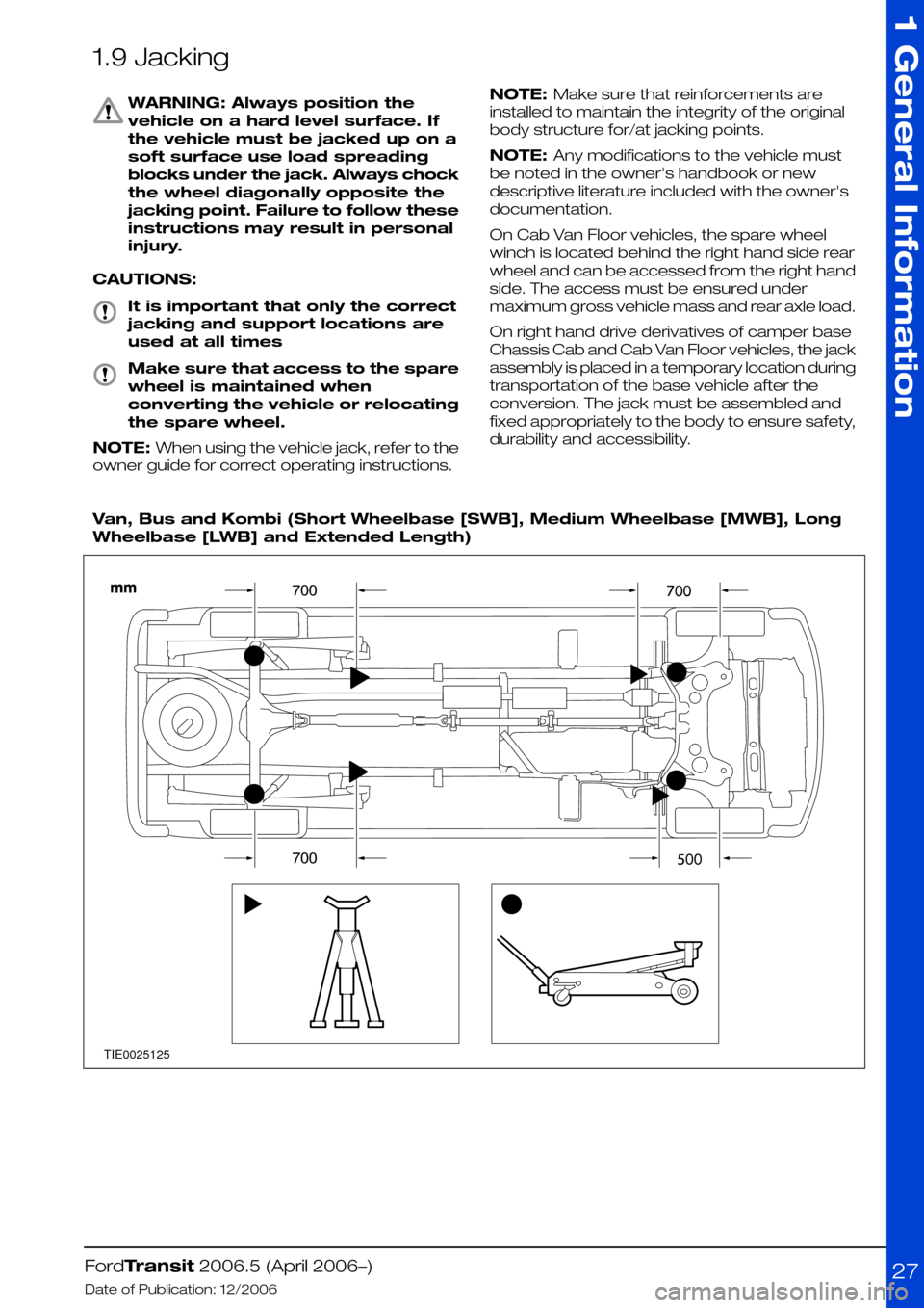
1.9 Jacking
WARNING: Always position the
vehicle on a hard level surface. If
the vehicle must be jacked up on a
soft surface use load spreading
blocks under the jack. Always chock
the wheel diagonally opposite the
jacking point. Failure to follow these
instructions may result in personal
injury.
CAUTIONS:
It is important that only the correct
jacking and support locations are
used at all times
Make sure that access to the spare
wheel is maintained when
converting the vehicle or relocating
the spare wheel.
NOTE: When using the vehicle jack, refer to the
owner guide for correct operating instructions.
NOTE: Make sure that reinforcements are
installed to maintain the integrity of the original
body structure for/at jacking points.
NOTE: Any modifications to the vehicle must
be noted in the owner's handbook or new
descriptive literature included with the owner's
documentation.
On Cab Van Floor vehicles, the spare wheel
winch is located behind the right hand side rear
wheel and can be accessed from the right hand
side. The access must be ensured under
maximum gross vehicle mass and rear axle load.
On right hand drive derivatives of camper base
Chassis Cab and Cab Van Floor vehicles, the jack
assembly is placed in a temporary location during
transportation of the base vehicle after the
conversion. The jack must be assembled and
fixed appropriately to the body to ensure safety,
durability and accessibility.
Van, Bus and Kombi (Short Wheelbase [SWB], Medium Wheelbase [MWB], Long
Wheelbase [LWB] and Extended Length)
FordTransit 2006.5 (April 2006–)
Date of Publication: 12/2006
1 General Information
27TIE0025125
Page 192 of 234

For Chassis Cab with tail lift design as described
above it is recommended to use unique body
sub-frame for fixing to Chassis Cab structure. For
connection between sub-frame Chassis Cab
body structure please refer to Figure E74696.
For Chassis Cab with under-slung tail lift load
capacity is up to 1000kg at 1000mm from rear
end of chassis frame to center of load if mounted
and functioning on centre line of vehicle. If
mounted and functioning off center line or at the
side of the vehicle load capacity is reduced to
500kg at 1000mm from side/rear end to center
of load.
Greater off-sets and/or loads require additional
stabilizing equipment such as outriggers or
ground jacks. It is recommended not to increase
vehicle body stress over limit as given by load
factors above. If uncertain please consult your
local national sales representative or the Vehicle
Converter Advisory Service [email protected].
It is the Vehicle converters responsibility to fit a
decal to the converted vehicle stating that the
equipment must not be used without
outriggers/ground jacks in operating position. It
is also the vehicle converters responsibility to
guarantee safe functioning of the equipment.
For hydraulic tail lifts as used for general loading
or more specialized for wheel-chair lifts please
refer to Figure E75874.
5.1.7 Partitions (Bulkhead) - Driver
and Front Passenger(s)
Protection on Van, Bus and Kombi
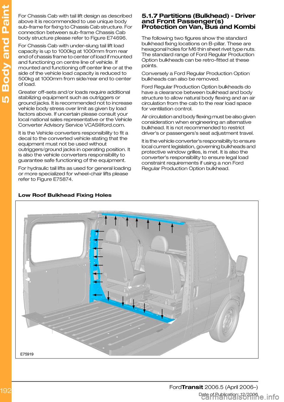
The following two figures show the standard
bulkhead fixing locations on B-pillar. These are
hexagonal holes for M6 thin sheet rivet type nuts.
The standard range of Ford Regular Production
Option bulkheads can be retro-fitted at these
points.
Conversely a Ford Regular Production Option
bulkheads can also be removed.
Ford Regular Production Option bulkheads do
have a clearance between bulkhead and body
structure to allow natural body flexing and an air
circulation from the cab to the rear load space
for ventilation control.
Air circulation and body flexing must be also given
consideration when engineering an alternative
bulkhead. It is not recommended to restrict
driver’s or passengers’s seat adjustment travel.
It is the vehicle converter’s responsibility to ensure
local current legislation, governing bulkheads and
protective window grilles, is met. It is also the
converter’s responsibility to ensure legal load
constraint requirements if using a non Ford
Regular Production Option bulkhead.
Low Roof Bulkhead Fixing Holes
FordTransit 2006.5 (April 2006–)
Date of Publication: 12/2006
5 Body and Paint
192E75919
Page 231 of 234

Generator and Alternator...............................103
Glass, Frames and Mechanisms...................211
Ground Points..................................................140
H
Hardware—Specifications...............................43
Heated Seats...................................................210
Heated Windshield and Heated Rear Window.
213
Horn...................................................................108
How to Use This Manual....................................6
Hydraulic Brake Actuation...............................64
Hydraulic Lifting Equipment for Van, Bus, Kombi
and Chassis Cab...........................................186
I
Important Safety Instructions............................6
Information and Entertainment System -
General Information—Specifications...........112
Installation and Routing Guides.....................134
Instrument Cluster...........................................107
Integrated Bodies and Conversions.............177
Interior Lighting.................................................118
Introduction..........................................................6
J
Jacking................................................................27
K
Kerb Mass Data.................................................62
L
Lamps for Wide Vehicles.................................117
Lamps – Front and Rear Fog Lights..............117
Lamps – Hazard / Direction Indication..........117
Legal and Vehicle Type Approval......................7
Legal Obligations and Liabilities.........................7
Legislation.........................................................109
Lifting...................................................................29
Load Apportioning Valves................................64
Load Compartment Interior Lining...............203
Load Distribution—Specifications...................44
Load Distribution Calculations - Driver and
Passenger Weight Distribution.....................44
M
Manual Transmission........................................83
Minimum Requirements for Brake system and
Load Apportioning Valves ...............................8
Mirrors for Wide Vehicles...............................208
Module Communications
Network—Specifications................................94
Mounting Points and Tubing.........................222
N
Noise, Vibration and Harshness (NVH)...........31
Non Standard Rear Chassis Frame Extension.
226
P
Package and Ergonomics—Specifications....
34
Package and Ergonomics...............................33
Painting Road Wheels..............................60, 221
Parking Brake....................................................63
Partitions (Bulkhead) - Driver and Front
Passenger(s) Protection on Van, Bus and
Kombi..............................................................192
Possible Accessories.......................................113
Power Management Settings.........................95
Power Take Off...................................................61
Product Liability....................................................8
R
Racking Systems.............................................194
Radio Connector..............................................112
Rear Anti-Roll Bar..............................................59
Rear Seat Fixings Positions - Kombi............209
Rear Suspension...............................................59
Rear View Mirrors...........................................208
Rear Windows..................................................211
Recommended Main Dimensions.................34
Recommended Main Load Area Dimensions
for Bulkhead with Depression Driver Side....
39
Recommended Main Load Area Dimensions
for Bulkhead with Full Depression................40
Recommended Main Load Area Dimensions
for Double Cab In Van Bulkhead...................41
Recommended Nominal Body Lengths for
Chassis Cab models......................................36
Relays and Switches.......................................127
Relocated Parking Brake Lever......................63
Repairing Damaged Paint..............................221
Restraints System...............................................8
Reversing Lamps.............................................116
Road Safety..........................................................8
Roof Opening Panel........................................214
Roof Racks.......................................................216
Roof Ventilation................................................215
S
Safety Belt System.........................................220
Seats.................................................................209
Security, Anti Theft and Locking System
Security ..........................................................203
Self-Supporting Body Structure...................224
Spare Tire Access and Mounting.................229
Spare wheel.......................................................60
Special Conversions........................................131
Special Vehicle Option Auxiliary Fuse Box....
121
Index
231