warning light FORD TRANSIT 2006 7.G Body And Equipment Mounting Section Manual
[x] Cancel search | Manufacturer: FORD, Model Year: 2006, Model line: TRANSIT, Model: FORD TRANSIT 2006 7.GPages: 234, PDF Size: 33.19 MB
Page 4 of 234
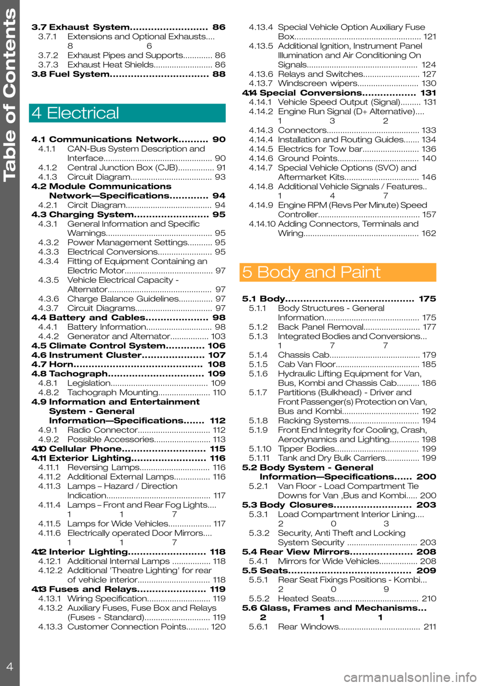
3.7Exhaust System..........................86
3.7.1Extensions and Optional Exhausts....
86
3.7.2Exhaust Pipes and Supports.............86
3.7.3Exhaust Heat Shields..........................86
3.8Fuel System.................................88
4 Electrical
4.1Communications Network..........90
4.1.1CAN-Bus System Description and
Interface................................................90
4.1.2Central Junction Box (CJB)................91
4.1.3Circuit Diagram....................................93
4.2Module Communications
Network—Specifications.............94
4.2.1Circit Diagram......................................94
4.3Charging System.........................95
4.3.1General Information and Specific
Warnings...............................................95
4.3.2Power Management Settings...........95
4.3.3Electrical Conversions........................95
4.3.4Fitting of Equipment Containing an
Electric Motor.......................................97
4.3.5Vehicle Electrical Capacity -
Alternator..............................................97
4.3.6Charge Balance Guidelines...............97
4.3.7Circuit Diagrams..................................97
4.4Battery and Cables.....................98
4.4.1Battery Information.............................98
4.4.2Generator and Alternator.................103
4.5Climate Control System.............106
4.6Instrument Cluster.....................107
4.7Horn...........................................108
4.8Tachograph................................109
4.8.1Legislation...........................................109
4.8.2Tachograph Mounting.......................110
4.9Information and Entertainment
System - General
Information—Specifications.......112
4.9.1Radio Connector................................112
4.9.2Possible Accessories.........................113
4.10Cellular Phone............................115
4.11Exterior Lighting.........................116
4.11.1Reversing Lamps...............................116
4.11.2Additional External Lamps................116
4.11.3Lamps – Hazard / Direction
Indication..............................................117
4.11.4Lamps – Front and Rear Fog Lights....
117
4.11.5Lamps for Wide Vehicles...................117
4.11.6Electrically operated Door Mirrors....
117
4.12Interior Lighting..........................118
4.12.1Additional Internal Lamps .................118
4.12.2Additional 'Theatre Lighting' for rear
of vehicle interior................................118
4.13Fuses and Relays.......................119
4.13.1Wiring Specification............................119
4.13.2Auxiliary Fuses, Fuse Box and Relays
(Fuses - Standard).............................119
4.13.3Customer Connection Points..........120
4.13.4Special Vehicle Option Auxiliary Fuse
Box........................................................121
4.13.5Additional Ignition, Instrument Panel
Illumination and Air Conditioning On
Signals.................................................124
4.13.6Relays and Switches.........................127
4.13.7Windscreen wipers...........................130
4.14Special Conversions..................131
4.14.1Vehicle Speed Output (Signal).........131
4.14.2Engine Run Signal (D+ Alternative)....
132
4.14.3Connectors.........................................133
4.14.4Installation and Routing Guides.......134
4.14.5Electrics for Tow bar.........................136
4.14.6Ground Points....................................140
4.14.7Special Vehicle Options (SVO) and
Aftermarket Kits.................................146
4.14.8Additional Vehicle Signals / Features..
147
4.14.9Engine RPM (Revs Per Minute) Speed
Controller.............................................157
4.14.10Adding Connectors, Terminals and
Wiring...................................................162
5 Body and Paint
5.1Body...........................................175
5.1.1Body Structures - General
Information..........................................175
5.1.2Back Panel Removal.........................177
5.1.3Integrated Bodies and Conversions...
177
5.1.4Chassis Cab........................................179
5.1.5Cab Van Floor.....................................185
5.1.6Hydraulic Lifting Equipment for Van,
Bus, Kombi and Chassis Cab..........186
5.1.7Partitions (Bulkhead) - Driver and
Front Passenger(s) Protection on Van,
Bus and Kombi..................................192
5.1.8Racking Systems...............................194
5.1.9Front End Integrity for Cooling, Crash,
Aerodynamics and Lighting.............198
5.1.10Tipper Bodies.....................................199
5.1.11Tank and Dry Bulk Carriers...............199
5.2Body System - General
Information—Specifications......200
5.2.1Van Floor - Load Compartment Tie
Downs for Van ,Bus and Kombi.....200
5.3Body Closures..........................203
5.3.1Load Compartment Interior Lining....
203
5.3.2Security, Anti Theft and Locking
System Security ...............................203
5.4Rear View Mirrors.....................208
5.4.1Mirrors for Wide Vehicles.................208
5.5Seats.........................................209
5.5.1Rear Seat Fixings Positions - Kombi...
209
5.5.2Heated Seats.....................................210
5.6Glass, Frames and Mechanisms...
211
5.6.1Rear Windows....................................211
Table of Contents
4
Page 7 of 234
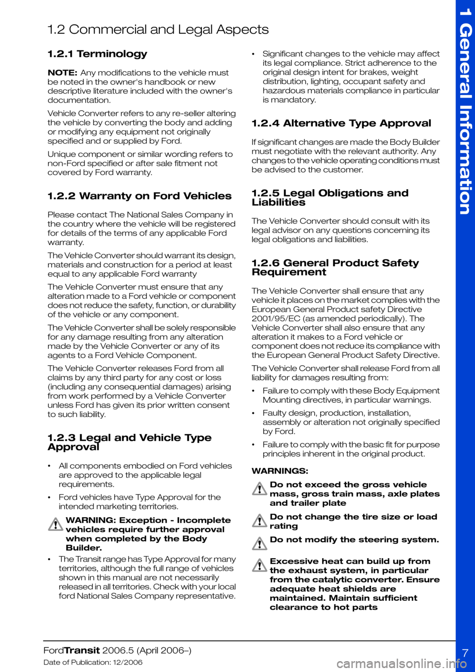
1.2 Commercial and Legal Aspects
1.2.1 Terminology
NOTE: Any modifications to the vehicle must
be noted in the owner's handbook or new
descriptive literature included with the owner's
documentation.
Vehicle Converter refers to any re-seller altering
the vehicle by converting the body and adding
or modifying any equipment not originally
specified and or supplied by Ford.
Unique component or similar wording refers to
non-Ford specified or after sale fitment not
covered by Ford warranty.
1.2.2 Warranty on Ford Vehicles
Please contact The National Sales Company in
the country where the vehicle will be registered
for details of the terms of any applicable Ford
warranty.
The Vehicle Converter should warrant its design,
materials and construction for a period at least
equal to any applicable Ford warranty
The Vehicle Converter must ensure that any
alteration made to a Ford vehicle or component
does not reduce the safety, function, or durability
of the vehicle or any component.
The Vehicle Converter shall be solely responsible
for any damage resulting from any alteration
made by the Vehicle Converter or any of its
agents to a Ford Vehicle Component.
The Vehicle Converter releases Ford from all
claims by any third party for any cost or loss
(including any consequential damages) arising
from work performed by a Vehicle Converter
unless Ford has given its prior written consent
to such liability.
1.2.3 Legal and Vehicle Type
Approval
•All components embodied on Ford vehicles
are approved to the applicable legal
requirements.
•Ford vehicles have Type Approval for the
intended marketing territories.
WARNING: Exception - Incomplete
vehicles require further approval
when completed by the Body
Builder.
•The Transit range has Type Approval for many
territories, although the full range of vehicles
shown in this manual are not necessarily
released in all territories. Check with your local
ford National Sales Company representative.
•Significant changes to the vehicle may affect
its legal compliance. Strict adherence to the
original design intent for brakes, weight
distribution, lighting, occupant safety and
hazardous materials compliance in particular
is mandatory.
1.2.4 Alternative Type Approval
If significant changes are made the Body Builder
must negotiate with the relevant authority. Any
changes to the vehicle operating conditions must
be advised to the customer.
1.2.5 Legal Obligations and
Liabilities
The Vehicle Converter should consult with its
legal advisor on any questions concerning its
legal obligations and liabilities.
1.2.6 General Product Safety
Requirement
The Vehicle Converter shall ensure that any
vehicle it places on the market complies with the
European General Product safety Directive
2001/95/EC (as amended periodically). The
Vehicle Converter shall also ensure that any
alteration it makes to a Ford vehicle or
component does not reduce its compliance with
the European General Product Safety Directive.
The Vehicle Converter shall release Ford from all
liability for damages resulting from:
•Failure to comply with these Body Equipment
Mounting directives, in particular warnings.
•Faulty design, production, installation,
assembly or alteration not originally specified
by Ford.
•Failure to comply with the basic fit for purpose
principles inherent in the original product.
WARNINGS:
Do not exceed the gross vehicle
mass, gross train mass, axle plates
and trailer plate
Do not change the tire size or load
rating
Do not modify the steering system.
Excessive heat can build up from
the exhaust system, in particular
from the catalytic converter. Ensure
adequate heat shields are
maintained. Maintain sufficient
clearance to hot parts
FordTransit 2006.5 (April 2006–)
Date of Publication: 12/2006
1 General Information
7
Page 33 of 234
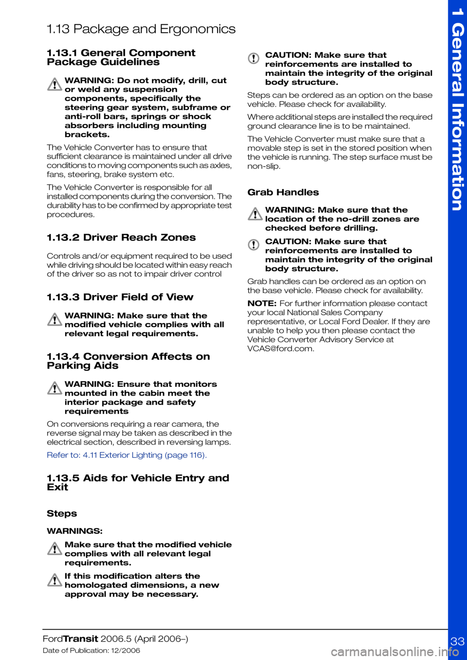
1.13 Package and Ergonomics
1.13.1 General Component
Package Guidelines
WARNING: Do not modify, drill, cut
or weld any suspension
components, specifically the
steering gear system, subframe or
anti-roll bars, springs or shock
absorbers including mounting
brackets.
The Vehicle Converter has to ensure that
sufficient clearance is maintained under all drive
conditions to moving components such as axles,
fans, steering, brake system etc.
The Vehicle Converter is responsible for all
installed components during the conversion. The
durability has to be confirmed by appropriate test
procedures.
1.13.2 Driver Reach Zones
Controls and/or equipment required to be used
while driving should be located within easy reach
of the driver so as not to impair driver control
1.13.3 Driver Field of View
WARNING: Make sure that the
modified vehicle complies with all
relevant legal requirements.
1.13.4 Conversion Affects on
Parking Aids
WARNING: Ensure that monitors
mounted in the cabin meet the
interior package and safety
requirements
On conversions requiring a rear camera, the
reverse signal may be taken as described in the
electrical section, described in reversing lamps.
Refer to: 4.11 Exterior Lighting (page 116).
1.13.5 Aids for Vehicle Entry and
Exit
Steps
WARNINGS:
Make sure that the modified vehicle
complies with all relevant legal
requirements.
If this modification alters the
homologated dimensions, a new
approval may be necessary.
CAUTION: Make sure that
reinforcements are installed to
maintain the integrity of the original
body structure.
Steps can be ordered as an option on the base
vehicle. Please check for availability.
Where additional steps are installed the required
ground clearance line is to be maintained.
The Vehicle Converter must make sure that a
movable step is set in the stored position when
the vehicle is running. The step surface must be
non-slip.
Grab Handles
WARNING: Make sure that the
location of the no-drill zones are
checked before drilling.
CAUTION: Make sure that
reinforcements are installed to
maintain the integrity of the original
body structure.
Grab handles can be ordered as an option on
the base vehicle. Please check for availability.
NOTE: For further information please contact
your local National Sales Company
representative, or Local Ford Dealer. If they are
unable to help you then please contact the
Vehicle Converter Advisory Service at
[email protected].
FordTransit 2006.5 (April 2006–)
Date of Publication: 12/2006
1 General Information
33
Page 91 of 234
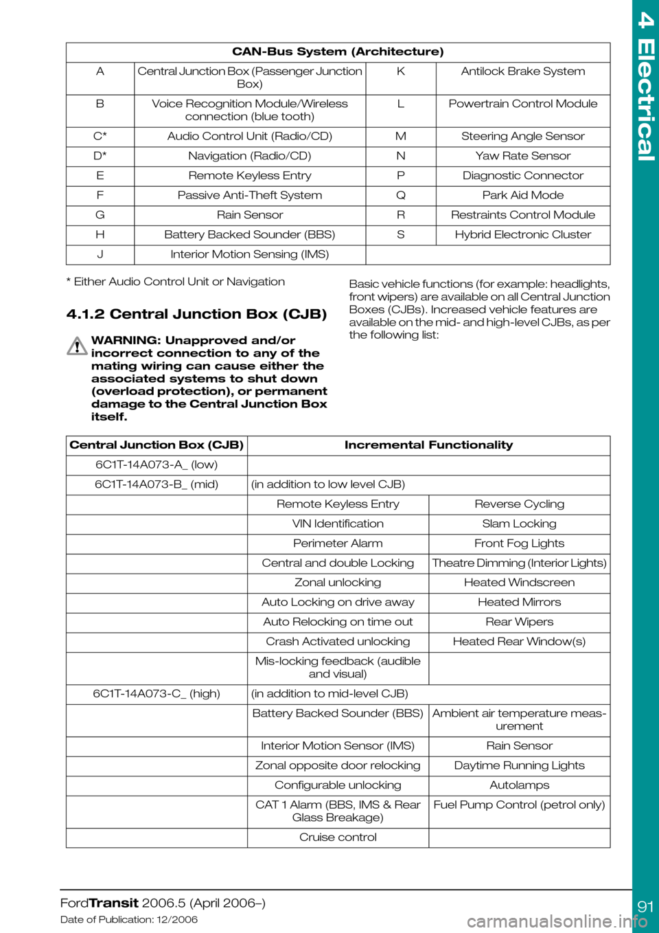
CAN-Bus System (Architecture)
Antilock Brake SystemKCentral Junction Box (Passenger Junction
Box)
A
Powertrain Control ModuleLVoice Recognition Module/Wireless
connection (blue tooth)
B
Steering Angle SensorMAudio Control Unit (Radio/CD)C*
Yaw Rate SensorNNavigation (Radio/CD)D*
Diagnostic ConnectorPRemote Keyless EntryE
Park Aid ModeQPassive Anti-Theft SystemF
Restraints Control ModuleRRain SensorG
Hybrid Electronic ClusterSBattery Backed Sounder (BBS)H
Interior Motion Sensing (IMS)J
* Either Audio Control Unit or Navigation
4.1.2 Central Junction Box (CJB)
WARNING: Unapproved and/or
incorrect connection to any of the
mating wiring can cause either the
associated systems to shut down
(overload protection), or permanent
damage to the Central Junction Box
itself.
Basic vehicle functions (for example: headlights,
front wipers) are available on all Central Junction
Boxes (CJBs). Increased vehicle features are
available on the mid- and high-level CJBs, as per
the following list:
Incremental FunctionalityCentral Junction Box (CJB)
6C1T-14A073-A_ (low)
(in addition to low level CJB)6C1T-14A073-B_ (mid)
Reverse CyclingRemote Keyless Entry
Slam LockingVIN Identification
Front Fog LightsPerimeter Alarm
Theatre Dimming (Interior Lights)Central and double Locking
Heated WindscreenZonal unlocking
Heated MirrorsAuto Locking on drive away
Rear WipersAuto Relocking on time out
Heated Rear Window(s)Crash Activated unlocking
Mis-locking feedback (audible
and visual)
(in addition to mid-level CJB)6C1T-14A073-C_ (high)
Ambient air temperature meas-
urement
Battery Backed Sounder (BBS)
Rain SensorInterior Motion Sensor (IMS)
Daytime Running LightsZonal opposite door relocking
AutolampsConfigurable unlocking
Fuel Pump Control (petrol only)CAT 1 Alarm (BBS, IMS & Rear
Glass Breakage)
Cruise control
FordTransit 2006.5 (April 2006–)
Date of Publication: 12/2006
4 Electrical
91
Page 95 of 234
4.3 Charging System
4.3.1 General Information and
Specific Warnings
The Transit electrical system is a 12-Volt supply
with a negative earth return. The alternator and
battery equipment used as standard are
designed for normal operations with the type of
engine fitted. Higher capacity batteries are
available as standard production options and
special vehicle options. Before installing additional
electrical equipment check that the battery
capacity, harness load capability, and alternator
output are suitable for the extra load.
The battery capacity and charge available from
the alternator must be adequate to ensure
engine cranking in unfavorable climatic conditions
but excessive battery capacity could damage
the starter motor.
The Transit utilizes multiplexed vehicle electronics
- it is recommended that the appropriate Ford
proprietary accessory systems are used.
Inappropriate or incorrect connection of
additional equipment could cause mis-operation,
or damage to the vehicle, and so invalidate any
warranty.
Additional connection points are provided
specifically for customer use (except M1 and M2
Bus), and are located on the outside of the
driver's seat base.
Do not jump-start the vehicle directly from the
battery. Use designated jump-start points. Refer
to the owners literature.
4.3.2 Power Management
Settings
There are four Power Management Settings
available:
•Factory
•Transport
•Normal
•Crash
Factory and Transport modes are only active
with ignition off; with ignition on, the vehicle
operates with full functionality. When in Transport
mode, the interior lights, clocks, and power
locking and alarms (where fitted) do not work.
It is possible to switch from Transport Mode to
Normal Mode without the use of any ancillary
equipment, but not vice versa. To change mode,
the brake pedal must be depressed five times,
and the hazard warning switch operated twice
(in any combination) within 10 seconds.
WARNING: It is not possible to return
the transport setting without using
the vehicle's diagnostics.
At the end of production, the vehicle is
configured to the transport setting to minimize
power consumption. As part of the Pre Delivery
Inspection process at the Ford dealership, the
vehicle is reconfigured to normal operation.
4.3.3 Electrical Conversions
Operator requirements for additional and
specialised electrical equipment varies. The
vehicle converter/modifier must, therefore,
consider the following points when designing the
installation:
•Legality and regulatory conformity of the base
vehicle.
•Drive-ability and serviceability of the base
vehicle.
•The effect of regulations governing the
proposed conversion including National
Legislation in the country of sale.
•The method of integrating the circuit into the
base vehicle.
•No additional circuits are to be run alongside
the electrical circuits (shown in blue in the
figure below) associated with the
Management System (shown in green in the
figure below), due to the possible Electro
Motive Force (EMF) effect on the circuits.
FordTransit 2006.5 (April 2006–)
Date of Publication: 12/2006
4 Electrical
95
Page 116 of 234
4.11 Exterior Lighting
Where the following text makes reference to the
addition of wires
Refer to: 4.14 Special Conversions (page 131).
(Adding Connectors, Terminals and Wiring)
WARNING: Make sure that the
modified vehicle complies with all
relevant legal requirements.
4.11.1 Reversing Lamps
These are hard-wired, activated by the reversing
switch on the transmission and passing through
the Central Junction Box where the signal is
sensed. A marginal increase in current (via a relay
or buffered electrical input) is permissible to
trigger a rear-view camera system, or audible
device.
4.11.2 Additional External Lamps
All power for additional exterior lamps must be
taken through the Auxiliary Fuse Box with a
suitable switch and / or relay as required.
Refer to: 4.13 Fuses and Relays (page 119).
• If CAT 6 directional indicators are to be fitted,
the Central Junction Box will need to be
configured for this.
• The load on the reversing lamps should not
exceed a total of 3A (42W).
Lighting Loads
Trailer TowLong Wheel-
base/
Extended
Frame /
Chassis Cab
/ Van
Head
Lamp
Leveling
VehicleMax.
Load
Controlling
Device
Central Junction
Box (CJB)
Outputs
-40~-2x10W60WRelay (F79)Licence Plate Supply
10W
(+2x10W)**
9W^9W15W63WRelay (F76)position Lamp Left (+
Leveling)
10W**9W^9W15W43WRelay (F75)position Lamp Right
(+ Leveling)
---21W + 21W*63WHigh Side
Driver
Direction Indication
Front Left
---21WDirection Indication
Rear Left
---21W + 21W*63WHigh Side
Driver
Direction Indication
Front Right
---21WDirection Indication
Rear Right
Symbols used
Front Dl + Turn Signal side Repeater*
Turn Signal Side Marker (5W) + Roof Marker (4W)^
6 x Side Marker (5W) + 2 x End Outline Marker (5W)~
Worst cases; left supply includes licence plate**
For trailer tow lighting relating to that system.
Refer to: 4.14 Special Conversions (page 131).
(Electrics for Tow bar)
Head Lamps
5AF75
7.5AF76
7.5AF79
FordTransit 2006.5 (April 2006–)
Date of Publication: 12/2006
4 Electrical
116
Page 117 of 234
4.11.3 Lamps – Hazard / Direction
Indication
The maximum permissible load with the standard
system is:
•3 x 21W – front and rear indicators + side
repeaters (Left Hand Side)
•3 x 21W – front and rear indicators + side
repeaters (Right Hand Side)
That is:- 63W per side maximum.
4.11.4 Lamps – Front and Rear
Fog Lights
National Regulations regarding inter-connection
with other front and rear fog lights must be
checked before designing the wiring circuit.
For trailer tow for rear fog lighting relating to that
system.
Refer to: 4.14 Special Conversions (page 131).
(Electrics for Tow bar)
4.11.5 Lamps for Wide Vehicles
Lamps – End outline and side marker
lamps
All Chassis Cab vehicles are fitted with front
marker lamps on the cab roof as standard, less
roof marker lamps they are optional. Where
additional side marker lamps and rear outline
marker lamps are required to comply with local
regulations, access to the appropriate signals
may be obtained from the licence plate lamps.
A special jumper link is available for this purpose
from the local Ford dealer.
The maximum permissible load with the standard
system is:
NOTE: For various vehicles Cat 6 repeater
lamps must be fitted. See legislation for full
details.
•6 x 5W – side marker
•2 x 5W – end outline marker
•2 x 5W – Cat 6
•2 x 4W – roof marker
4.11.6 Electrically operated Door
Mirrors
WARNING: Do not tamper with the
base system (controlled by Central
Junction Box and multiplex
architecture) and any feeds taken
from the associated wiring or
controller.
NOTE: These options are not suitable for
aftermarket or Body Builder fit.
Refer to: 1.14 (page 34).
FordTransit 2006.5 (April 2006–)
Date of Publication: 12/2006
4 Electrical
117
Page 134 of 234
Where wires are required to be extended, break
in points should only be at existing connector
points and only Ford approved connectors should
be used.
Ford approved link harnesses should be used.
Unused Connectors
The harnesses may have a number of unused
connectors – these are dedicated to other
features and options, e.g. heated seats, but are
not always present depending on level of
harness fitted. Ford do not recommend the use
of these connectors for any other purpose than
that intended by design.
Power Outlet / Cigar Lighter
Both features adopt a 20A fusing strategy. With
a single battery system, continued loading of
these features will lead to battery drain, and risk
vehicle starting. If continuous power is required,
a second battery option should be installed and
the customer connection points, where fitted,
utilized.
4.14.4 Installation and Routing Guides
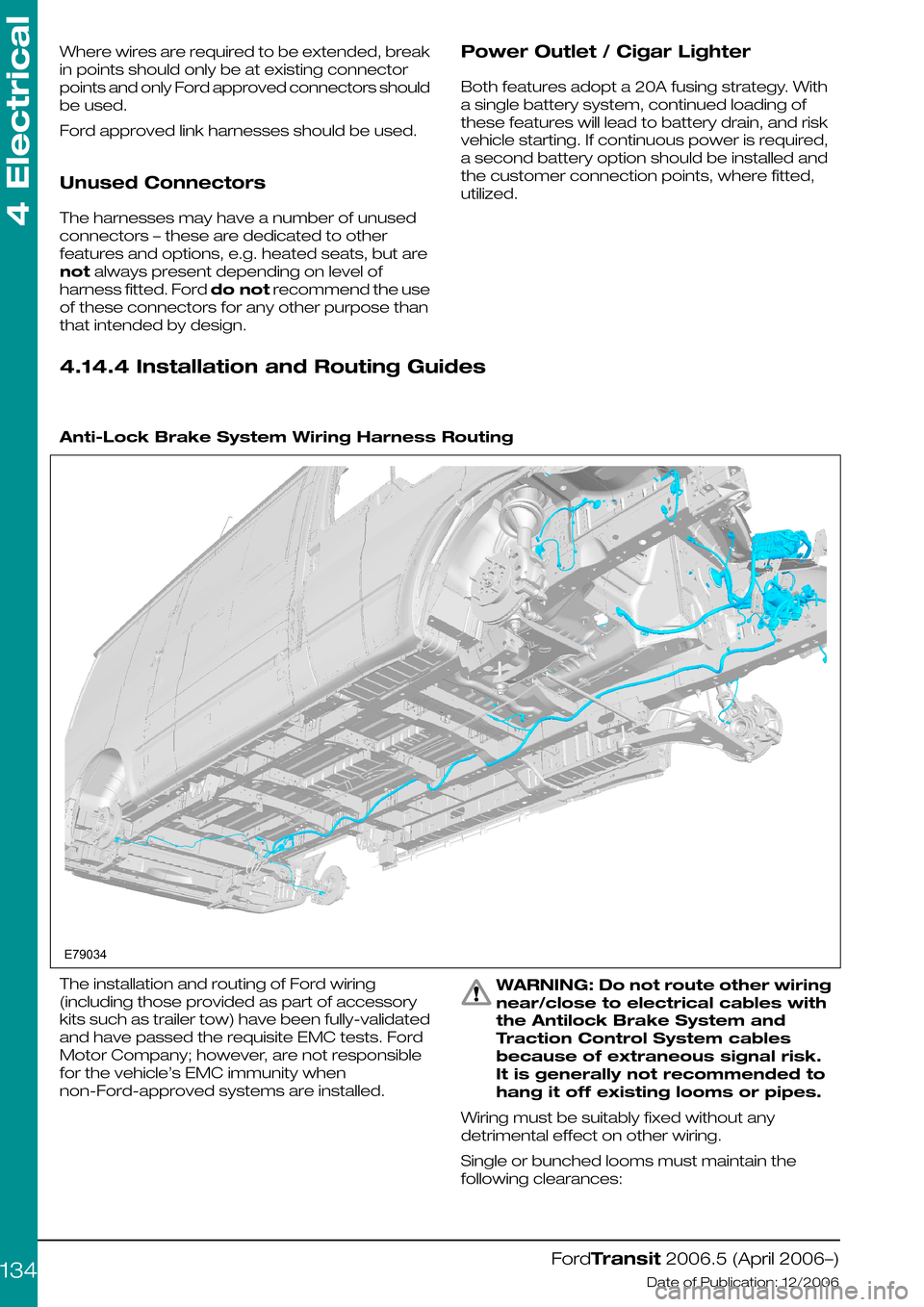
Anti-Lock Brake System Wiring Harness Routing
The installation and routing of Ford wiring
(including those provided as part of accessory
kits such as trailer tow) have been fully-validated
and have passed the requisite EMC tests. Ford
Motor Company; however, are not responsible
for the vehicle’s EMC immunity when
non-Ford-approved systems are installed.
WARNING: Do not route other wiring
near/close to electrical cables with
the Antilock Brake System and
Traction Control System cables
because of extraneous signal risk.
It is generally not recommended to
hang it off existing looms or pipes.
Wiring must be suitably fixed without any
detrimental effect on other wiring.
Single or bunched looms must maintain the
following clearances:
FordTransit 2006.5 (April 2006–)
Date of Publication: 12/2006
4 Electrical
134E79034
Page 137 of 234
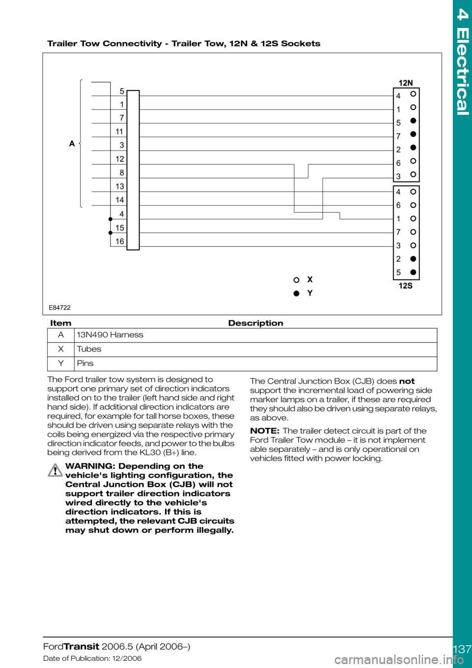
Trailer Tow Connectivity - Trailer Tow, 12N & 12S Sockets
DescriptionItem
13N490 HarnessA
TubesX
PinsY
The Ford trailer tow system is designed to
support one primary set of direction indicators
installed on to the trailer (left hand side and right
hand side). If additional direction indicators are
required, for example for tall horse boxes, these
should be driven using separate relays with the
coils being energized via the respective primary
direction indicator feeds, and power to the bulbs
being derived from the KL30 (B+) line.
WARNING: Depending on the
vehicle's lighting configuration, the
Central Junction Box (CJB) will not
support trailer direction indicators
wired directly to the vehicle's
direction indicators. If this is
attempted, the relevant CJB circuits
may shut down or perform illegally.
The Central Junction Box (CJB) does not
support the incremental load of powering side
marker lamps on a trailer, if these are required
they should also be driven using separate relays,
as above.
NOTE: The trailer detect circuit is part of the
Ford Trailer Tow module – it is not implement
able separately – and is only operational on
vehicles fitted with power locking.
FordTransit 2006.5 (April 2006–)
Date of Publication: 12/2006
4 Electrical
137E8472241572634617325517113128131441516
Page 154 of 234
harness that provides roof-mounted rear turn
indicators, powered via relays. This should be
used in conjunction with SVO fusebox.
3.Chassis cab LED rear lamp cluster
replacement recommendations, especially
turn indicator relay implications – see lighting
load table. Generally the use of LED equivalent
lighting systems reduces the electrical load on
the vehicle; however, special care needs to
be taken with respect to any change to or
addition of turn indicator lights. Depending on
the current requirements of the LED(s)
compared to the bulb it is replacing, a ballast
resistor may be required, if not already
integrated into the LED lamp assembly.
Without this, bulb outage detection for turn
indicators will be affected, which is a legal
requirement.
Additional turn indicators must be powered
through relays (max 300mA), driven by existing
turn lights. The maximum load that the Central
Junction Box can drive is 3 x 21W per side (front,
rear and CAT 6 turn indicators); but even if the
vehicle is not fitted with the CAT 6 lights, the feeds
for these should not be used as the Central
Junction Box would need reconfiguring, which
could have safety as well as functional
implications.
4.Special Vehicle Option beacon switch: wiring
locations, circuit diagrams and max amperage
– see Special Vehicle Option fuse box
schematic (max current is 15A); there is
provision for the Special Vehicle Option beacon
switch in an empty switch location on the
instrument panel.
5.Rear loom connector detail location and supply
details for retro-fit loom extension for
example:- when extending a medium wheel
base, long wheel base or extended frame
overhang, what connectors do they use to
make a plug and play loom extension? – for
chassis cab vehicles, there is an Special
Vehicle Option extension loom for rear lamps
(part number 6C1V-14408-A*). There is not, at
present, a similar loom for Van, Bus and
Kombi's, although the appropriate mating
connector is now tooled, so this would be
possible.
Miscellaneous Systems
Handbrake on - Cluster Warning Light -
Unless the vehicle is specified with options that
drive the handbrake warning light (for example
ESP, Australia market), the components making
up this system are not fitted. We do not
recommend installation of this feature as an
aftermarket addition. There are several reasons
for this:
1.Not all circuits carry the requisite wire as a give
away:
•The wires might be part of the main vehicle
harness (14401) even if not used – for example
camper vehicles are normally ordered with
power mirrors, and the wires will be present
as a give-away.
•The seat pedestal harness (14K076), however,
is vehicle specific – if the handbrake is not part
of the specification, it will not be present or
give-away. This harness would need to be
changed to the compatible part that also
includes the handbrake warning light circuit.
2.The handbrake switch (part number
2F2T-15852-A*) together with its short jumper
harness (6C1T-15K857-A*) would need to be
obtained and fitted.
3.The handbrake warning light is in all clusters,
but unless the vehicle config. parameter
“parking brake switch” is set, the Central
Junction Box will not read this input, and hence
NO CAN message sent to the cluster.
Reconfiguration can only be done at a Ford
Dealer.
NOTE: If a vehicle already has a handbrake
warning light in the cluster, or one is installed as
per the Ford design, it is not possible to utilize the
wire from the handbrake switch as part of an
interlock circuit (this is a pull up resistor input that
provides a wetting current of 20mA – anything in
excess of this, for example through additional
circuitry, will almost certainly damage the Central
Junction Box). If there is no handbrake switch
installed, it would be possible to add one and
utilize this as part of a separate circuit, up to a
maximum current of 500mA through the switch.
Reverse Sensors (Rear Park Aid
Module)- The factory-fit option is a CAN-based
system, but for Van, Bus, and Kombi vehicles
only. Stand-alone systems can be installed (for
example for chassis cab conversions), but would
need to utilize the PTA line of the radio if muting
is required.
Fuel Fired Heater (FFH)- Add FFH: wiring is
only present (give-away) in certain harnesses.
There was an aftermarket kit available for this
system on current Transit, which could probably
be “updated” to suit V347/8.
Fuel Fired Heater (FFH) - Programmable
FFH: this utilizes a timer/control module mounted
to the Instrument Panel, which necessitates
having the correct Instrument Panel harness
fitted. Retrofit of this would be a difficult.
For both systems, the appropriate 6C1T-14K132
harness would be required (suffix -A* for
Programmable FFH, and suffix –B* for Add FFH).
Central Locking
Locking is controlled by the Central Junction Box
module. There is current sensing on certain
locking circuit pins as part of the security system
– if these are tampered with, locking cannot be
guaranteed.
FordTransit 2006.5 (April 2006–)
Date of Publication: 12/2006
4 Electrical
154