FORD WINDSTAR 1999 2.G Owners Manual
Manufacturer: FORD, Model Year: 1999, Model line: WINDSTAR, Model: FORD WINDSTAR 1999 2.GPages: 248, PDF Size: 2.28 MB
Page 221 of 248

Maintenance
²Keep tires properly inflated and use only recommended size.
²Operating a vehicle with the wheels out of alignment will reduce fuel
economy.
²Use recommended engine oil. Refer toLubricant Specifications.
²Perform all regularly scheduled maintenance items. Follow the
recommended maintenance schedule and owner maintenance checks
found in your vehicle Scheduled Maintenance Guide.
Conditions
²Heavily loading a vehicle or towing a trailer may reduce fuel economy
at any speed.
²Carrying unnecessary weight may reduce fuel economy (approximately
2 km/h [1 mpg] is lost for every 180 kg [400 lb] of weight carried).
²Adding certain accessories to your vehicle (for example bug
deflectors, rollover/light bars, running boards, ski/luggage racks) may
reduce fuel economy.
²Use of fuel blended with alcohol may lower fuel economy.
²Fuel economy may decrease with lower temperatures during the first
12±16 km (8±10 miles) of driving.
²Flat terrain driving improves fuel economy over hilly roads.
²Transmissions give their best fuel economy when operated in the top
cruise gear and with steady pressure on the gas pedal.
²Close windows for high speed driving.
EPA window sticker
Every new vehicle should have the EPA window sticker. Contact your
dealer if the window sticker is not supplied with your vehicle. The EPA
window sticker should be your guide for the fuel economy comparisons
with other vehicles.
It is important to note the box in the lower left corner of the window
sticker. These numbers represent the Range of Km/L (MPG) expected on
the vehicle, depending upon the driver's method of operation and
conditions.
Maintenance and care
221
Page 222 of 248
EMISSION CONTROL SYSTEM
Your vehicle is equipped with various emission control components and a
catalytic converter which will enable your vehicle to comply with
applicable exhaust emission standards. To make sure that the catalytic
converter and other emission control components continue to work
properly:
²Use only unleaded fuel.
²Avoid running out of fuel.
²Do not turn off the ignition while your vehicle is moving, especially at
high speeds.
²Have the items listed in your Scheduled Maintenance Guide performed
according to the specified schedule.
The scheduled maintenance items listed in the Scheduled Maintenance
Guide are essential to the life and performance of your vehicle and to its
emissions system.
If other than Ford, Motorcraft or Ford-authorized parts are used for
maintenance replacements or for service of components affecting
emission control, such non-Ford parts should be equivalent to genuine
Ford Motor Company parts in performance and durability.
Do not park, idle, or drive your vehicle in dry grass or other dry
ground cover. The emission system heats up the engine
compartment and exhaust system, which can start a fire.
Illumination of the charging system warning light,Check Engine
indicator light or the temperature warning light, fluid leaks, strange
odors, smoke or loss of oil pressure, could indicate that the emission
control system is not working properly.
Exhaust leaks may result in entry of harmful and potentially
lethal fumes into the passenger compartment.
Maintenance and care
222
Page 223 of 248

Do not make any unauthorized changes to your vehicle or engine. By
law, vehicle owners and anyone who manufactures, repairs, items, sells,
leases, trades vehicles, or supervises a fleet of vehicles are not permitted
to intentionally remove an emission control device or prevent it from
working. Information about your vehicle's emission system is on the
Vehicle Emission Control Information Decal located on or near the
engine. This decal identifies engine displacement and gives some tune up
specifications.
Please consult your ªWarranty Guideº for complete emission warranty
information.
Readiness for inspection/maintenance (I/M) testing
In some localities, it may be a legal requirement to pass an I/M test of
the on-board diagnostic (OBD-II) system. If your ªCheck Engine/Service
Engine Soonº light is on, refer to the description in theWarning Lights
and Chimessection of theInstrumentationchapter. Your vehicle may
not pass the I/M test with the ªCheck Engine/Service Engine Soonº light
on.
If the vehicle's powertrain system or its battery has just been serviced,
the OBD-II system is reset to a ªnot ready for I/M testº condition. To
ready the OBD-II system for I/M testing, a minimum of 30 minutes of city
and highway driving is necessary as described below:
²First, at least 10 minutes of driving on an expressway or highway.
²Next, at least 20 minutes driving in stop-and-go, city-type traffic with
at least four idle periods.
Allow the vehicle to sit for at least eight hours without starting the
engine. Then, start the engine and complete the above driving cycle. The
engine must warm up to its normal operating temperature. Once started,
do not turn off the engine until the above driving cycle is complete.
Maintenance and care
223
Page 224 of 248
EXTERIOR BULBS
Replacing exterior bulbs
It is a good idea to check the operation of the following lights frequently:
²Headlamps
²Turn signals
²Cornering lamps
²High-mount brakelamp
²Tail lamps
²Brakelamps
²Backup lamps
²License plate lamps
Do not remove lamp bulbs unless they will be replaced immediately. If a
bulb is removed for an extended period of time, contaminants may enter
the lamp housings and affect performance.
Handle a halogen bulb carefully and keep out of children's reach.
Grasp the bulb only by its plastic base and do not touch the
glass; the oil from your hand could cause the bulb to break the next
time that the headlamps are operated.
Replacing headlamp bulbs
Handle a halogen headlamp bulb carefully and keep out of
children's reach. Grasp the bulb only by its plastic base and do
not touch the glass. The oil from your hand could cause the bulb to
break the next time the headlamps are operated.
To remove the headlamp bulb:
1. Make sure headlamp switch is in OFF position, then open the hood.
Maintenance and care
224
Page 225 of 248
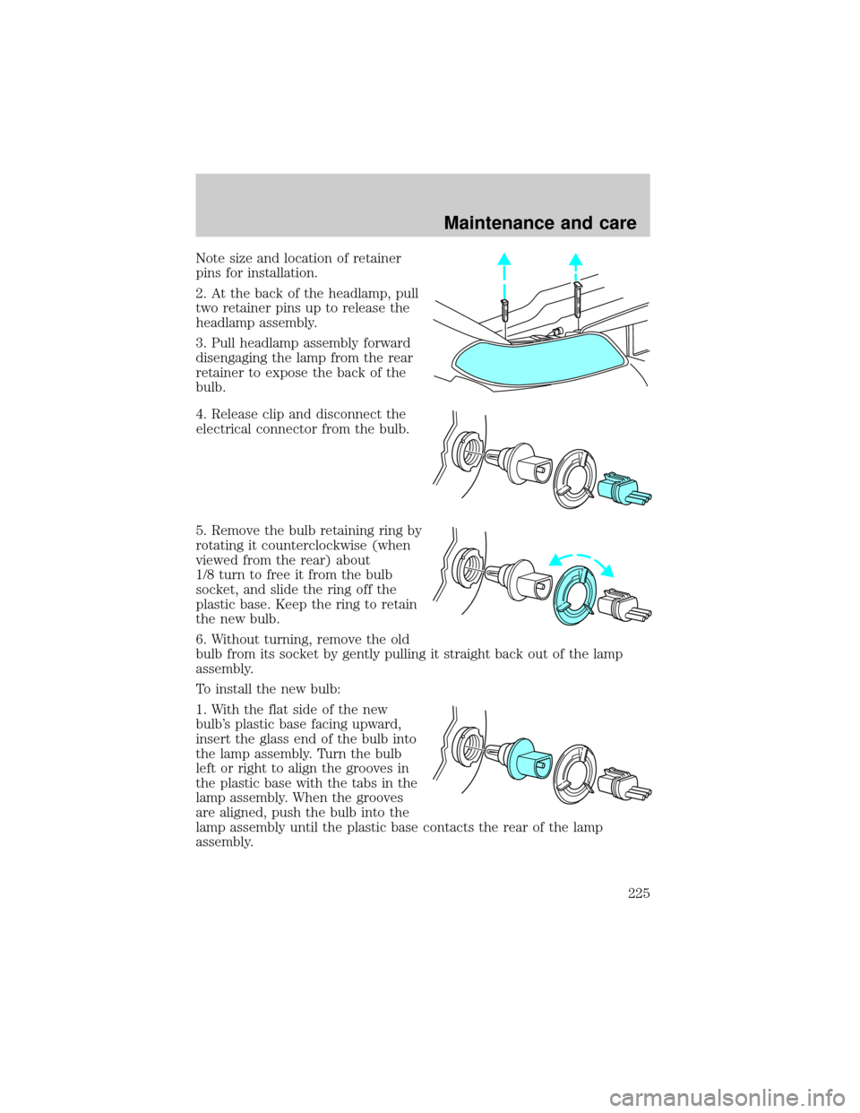
Note size and location of retainer
pins for installation.
2. At the back of the headlamp, pull
two retainer pins up to release the
headlamp assembly.
3. Pull headlamp assembly forward
disengaging the lamp from the rear
retainer to expose the back of the
bulb.
4. Release clip and disconnect the
electrical connector from the bulb.
5. Remove the bulb retaining ring by
rotating it counterclockwise (when
viewed from the rear) about
1/8 turn to free it from the bulb
socket, and slide the ring off the
plastic base. Keep the ring to retain
the new bulb.
6. Without turning, remove the old
bulb from its socket by gently pulling it straight back out of the lamp
assembly.
To install the new bulb:
1. With the flat side of the new
bulb's plastic base facing upward,
insert the glass end of the bulb into
the lamp assembly. Turn the bulb
left or right to align the grooves in
the plastic base with the tabs in the
lamp assembly. When the grooves
are aligned, push the bulb into the
lamp assembly until the plastic base contacts the rear of the lamp
assembly.
Maintenance and care
225
Page 226 of 248
2. Install the bulb retaining ring over the plastic base until it contacts the
rear of the socket by rotating clockwise until you feel a ªstop.º
3. Connect the electrical connector into the rear of the plastic base until
it snaps, locking it into position.
4. Install the headlamp on vehicle by aligning the lamp with the rear
retainer, push rearward and secure with two retainer pins.
5. Turn the headlamps on and make sure they work properly. If the
headlamp was correctly aligned before you changed the bulb, you should
not need to align it again.
Replacing front parking/turn signal bulbs
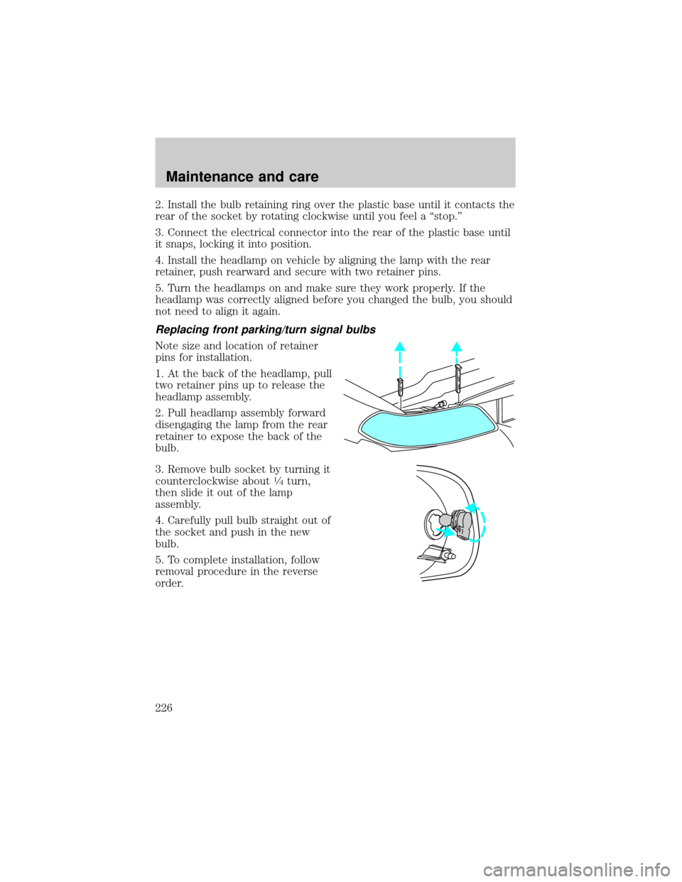
Note size and location of retainer
pins for installation.
1. At the back of the headlamp, pull
two retainer pins up to release the
headlamp assembly.
2. Pull headlamp assembly forward
disengaging the lamp from the rear
retainer to expose the back of the
bulb.
3. Remove bulb socket by turning it
counterclockwise about
1¤4turn,
then slide it out of the lamp
assembly.
4. Carefully pull bulb straight out of
the socket and push in the new
bulb.
5. To complete installation, follow
removal procedure in the reverse
order.
Maintenance and care
226
Page 227 of 248

Replacing tail lamp/backup lamp bulbs
1. Open the liftgate to expose the
tail lamp assemblies.
2. Remove the two screws from the
lamp assembly.
3. Carefully remove the lamp
assembly by pulling it rearward
about 45 degrees.
4. Rotate bulb socket
counterclockwise
1¤4turn and
remove from lamp assembly.
5. Pull bulb straight out of socket and push in new bulb.
6. To complete installation, follow the removal procedure in the reverse
order.
Replacing license plate lamp bulbs
To change the license plate bulbs:
1. Remove two screws and the
license plate lamp assembly from
the liftgate.
2. Remove bulb socket by pulling it
straight out of the lamp assembly.
3. Carefully pull the bulb out from
the socket and push in the new
bulb.
4. Push bulb socket in to the lamp
assembly.
5. Install the lamp assembly on
liftgate with two screws.
High-mount brakelamp bulbs
For bulb replacement, see a dealer or qualified technician.
Cornering lamp bulbs
For bulb replacement, see a dealer or qualified technician.
Maintenance and care
227
Page 228 of 248
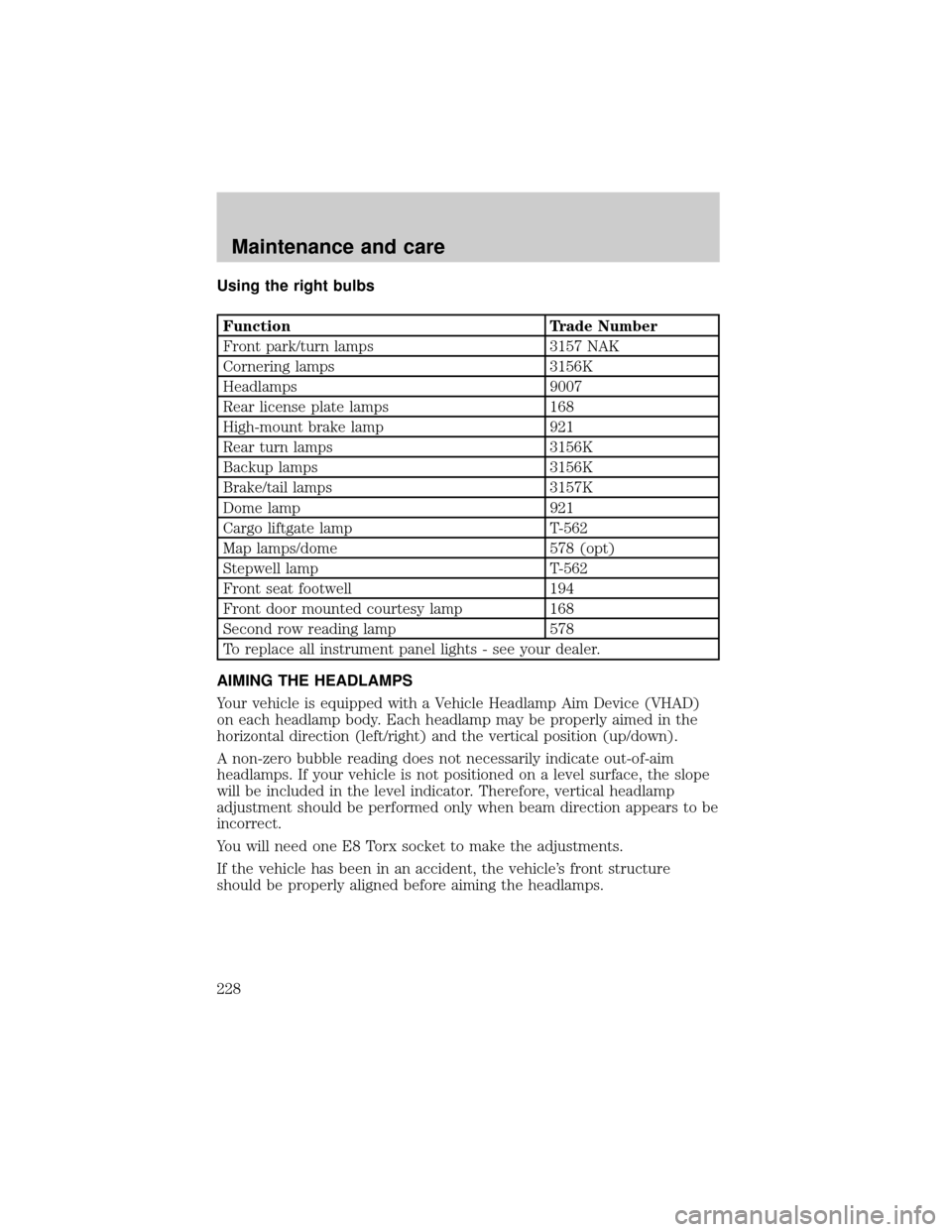
Using the right bulbs
Function Trade Number
Front park/turn lamps 3157 NAK
Cornering lamps 3156K
Headlamps 9007
Rear license plate lamps 168
High-mount brake lamp 921
Rear turn lamps 3156K
Backup lamps 3156K
Brake/tail lamps 3157K
Dome lamp 921
Cargo liftgate lamp T-562
Map lamps/dome 578 (opt)
Stepwell lamp T-562
Front seat footwell 194
Front door mounted courtesy lamp 168
Second row reading lamp 578
To replace all instrument panel lights - see your dealer.
AIMING THE HEADLAMPS
Your vehicle is equipped with a Vehicle Headlamp Aim Device (VHAD)
on each headlamp body. Each headlamp may be properly aimed in the
horizontal direction (left/right) and the vertical position (up/down).
A non-zero bubble reading does not necessarily indicate out-of-aim
headlamps. If your vehicle is not positioned on a level surface, the slope
will be included in the level indicator. Therefore, vertical headlamp
adjustment should be performed only when beam direction appears to be
incorrect.
You will need one E8 Torx socket to make the adjustments.
If the vehicle has been in an accident, the vehicle's front structure
should be properly aligned before aiming the headlamps.
Maintenance and care
228
Page 229 of 248
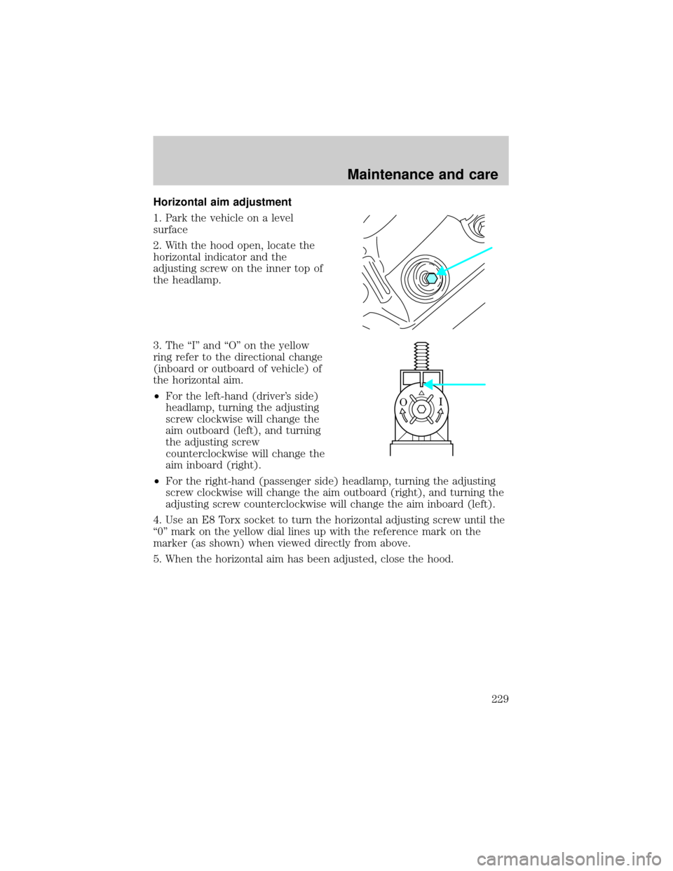
Horizontal aim adjustment
1. Park the vehicle on a level
surface
2. With the hood open, locate the
horizontal indicator and the
adjusting screw on the inner top of
the headlamp.
3. The ªIº and ªOº on the yellow
ring refer to the directional change
(inboard or outboard of vehicle) of
the horizontal aim.
²For the left-hand (driver's side)
headlamp, turning the adjusting
screw clockwise will change the
aim outboard (left), and turning
the adjusting screw
counterclockwise will change the
aim inboard (right).
²For the right-hand (passenger side) headlamp, turning the adjusting
screw clockwise will change the aim outboard (right), and turning the
adjusting screw counterclockwise will change the aim inboard (left).
4. Use an E8 Torx socket to turn the horizontal adjusting screw until the
ª0º mark on the yellow dial lines up with the reference mark on the
marker (as shown) when viewed directly from above.
5. When the horizontal aim has been adjusted, close the hood.
I O
Maintenance and care
229
Page 230 of 248
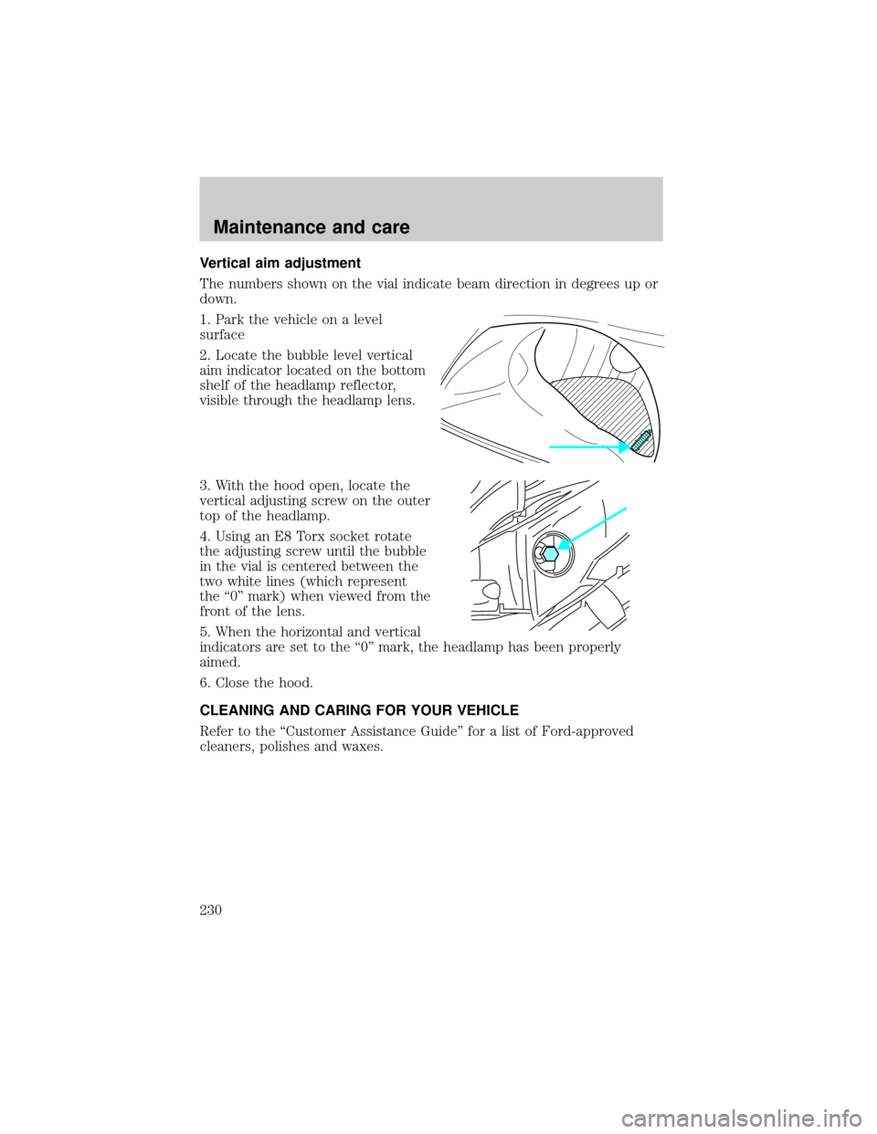
Vertical aim adjustment
The numbers shown on the vial indicate beam direction in degrees up or
down.
1. Park the vehicle on a level
surface
2. Locate the bubble level vertical
aim indicator located on the bottom
shelf of the headlamp reflector,
visible through the headlamp lens.
3. With the hood open, locate the
vertical adjusting screw on the outer
top of the headlamp.
4. Using an E8 Torx socket rotate
the adjusting screw until the bubble
in the vial is centered between the
two white lines (which represent
the ª0º mark) when viewed from the
front of the lens.
5. When the horizontal and vertical
indicators are set to the ª0º mark, the headlamp has been properly
aimed.
6. Close the hood.
CLEANING AND CARING FOR YOUR VEHICLE
Refer to the ªCustomer Assistance Guideº for a list of Ford-approved
cleaners, polishes and waxes.
DU
Maintenance and care
230