brake sensor FORD WINDSTAR 2000 2.G Owners Manual
[x] Cancel search | Manufacturer: FORD, Model Year: 2000, Model line: WINDSTAR, Model: FORD WINDSTAR 2000 2.GPages: 280, PDF Size: 2.49 MB
Page 22 of 280

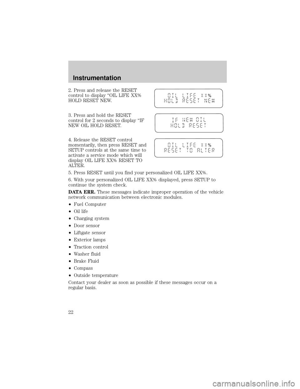
2. Press and release the RESET
control to display ªOIL LIFE XX%
HOLD RESET NEW.
3. Press and hold the RESET
control for 2 seconds to display ªIF
NEW OIL HOLD RESET.
4. Release the RESET control
momentarily, then press RESET and
SETUP controls at the same time to
activate a service mode which will
display OIL LIFE XX% RESET TO
ALTER.
5. Press RESET until you find your personalized OIL LIFE XX%.
6. With your personalized OIL LIFE XX% displayed, press SETUP to
continue the system check.
DATA ERR.These messages indicate improper operation of the vehicle
network communication between electronic modules.
²Fuel Computer
²Oil life
²Charging system
²Door sensor
²Liftgate sensor
²Exterior lamps
²Traction control
²Washer fluid
²Brake Fluid
²Compass
²Outside temperature
Contact your dealer as soon as possible if these messages occur on a
regular basis.
%
%
Instrumentation
22
Page 140 of 280

Replacing the second row bench seat belt assemblies after a
collision
All second row bench seat belt assemblies adjacent to a sliding door have
special energy management retractors designed to further reduce the
risk of injury in the event of a head-on collision. These retractors should
be replaced if they were used in any accident in which the front airbags
deploy. If the safety belt assemblies are not replaced, there may be
increased risk of injury in the event of a subsequent collision.
Failure to inspect and if necessary replace the safety belt
assembly under the above conditions could result in severe
personal injuries in the event of a collision.
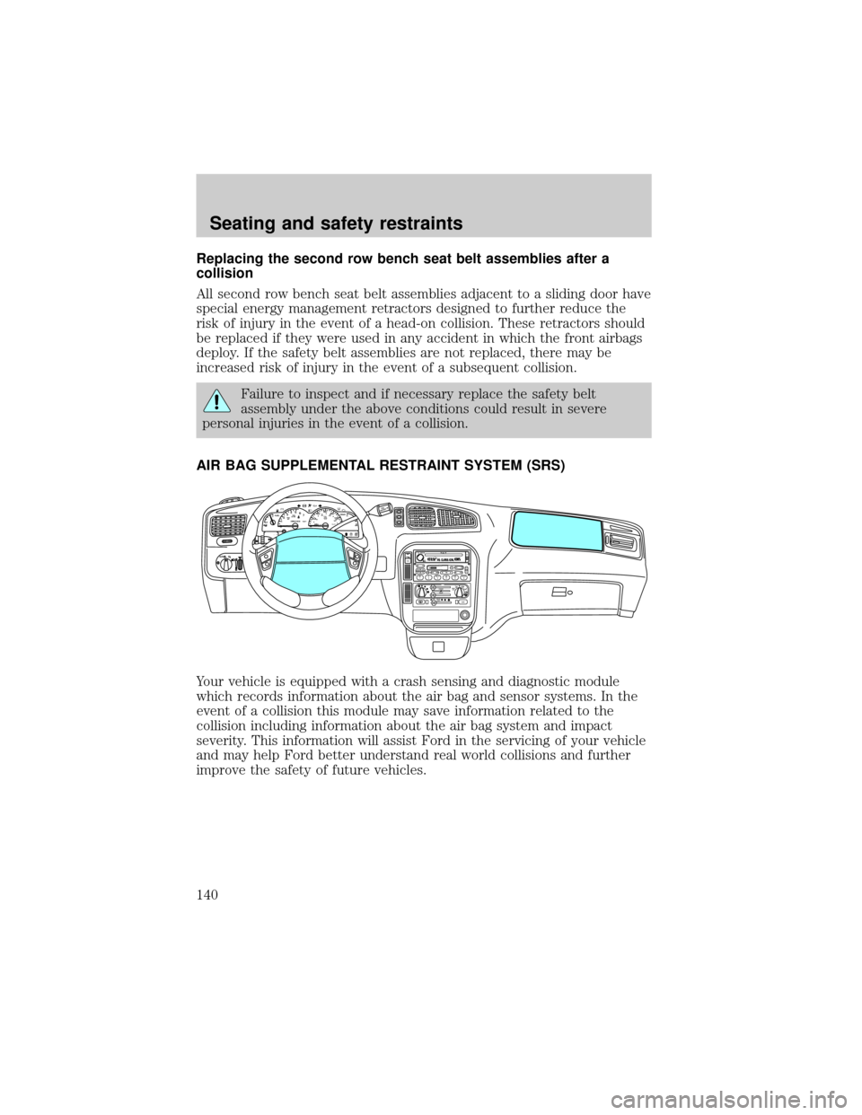
AIR BAG SUPPLEMENTAL RESTRAINT SYSTEM (SRS)
Your vehicle is equipped with a crash sensing and diagnostic module
which records information about the air bag and sensor systems. In the
event of a collision this module may save information related to the
collision including information about the air bag system and impact
severity. This information will assist Ford in the servicing of your vehicle
and may help Ford better understand real world collisions and further
improve the safety of future vehicles.
mi
FM1STSTAUTOP
12345
6
7RPMX1000 THEFT TRAC
ACTIVE TRAC
OFFFFUEL
E404080
120
1602060
80100 MPHTEMP
Hkm/hBRAKEO/D
OFFO
/D
O
N
/O
FFINFOSETUP
RESET
DISC
EJMUTEVOL - PUSH ONOFF
T/CFM1
REW FFSCAN
BASS TREB SEL BALTAPE EJ CD
FADEAUTO
CLK
SIDE 1-2 COMP SHUFFLESEEK
TUNE AM FM12 3456DOLBY B NR
A/CFRONT
REAR
OFFMAX
A/C
REAR
CONT
Seating and safety restraints
140
Page 167 of 280

The parking brake is not recommended to stop a moving vehicle.
However, if the normal brakes fail, the parking brake can be used to stop
your vehicle in an emergency. Since the parking brake applies only the
rear brakes, the vehicle's stopping distance will increase greatly and the
handling of your vehicle will be adversely affected.
Always set the parking brake fully and make sure that the
gearshift is securely latched in P (Park) (automatic transaxle).
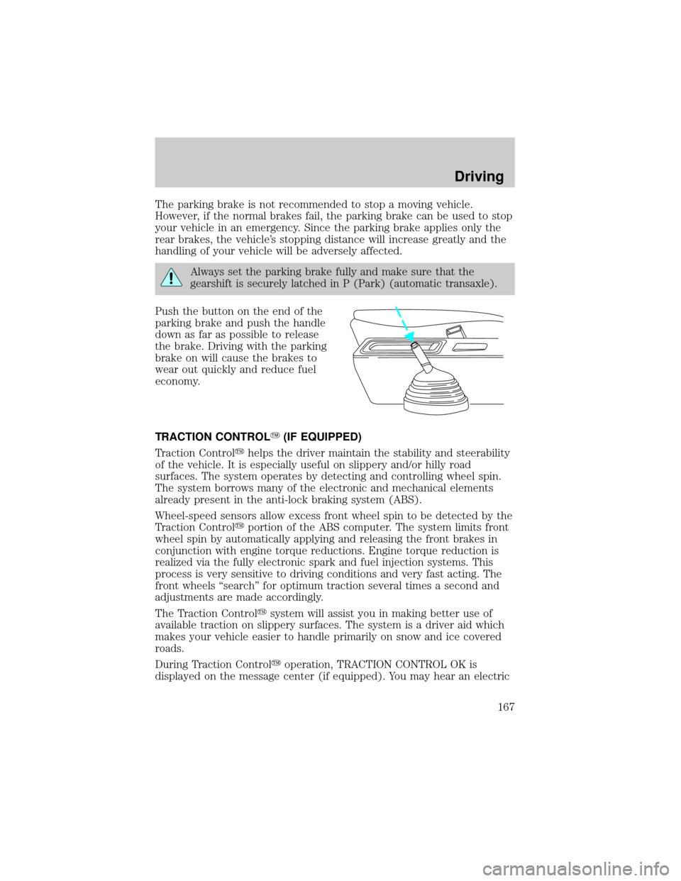
Push the button on the end of the
parking brake and push the handle
down as far as possible to release
the brake. Driving with the parking
brake on will cause the brakes to
wear out quickly and reduce fuel
economy.
TRACTION CONTROLY(IF EQUIPPED)
Traction Controlyhelps the driver maintain the stability and steerability
of the vehicle. It is especially useful on slippery and/or hilly road
surfaces. The system operates by detecting and controlling wheel spin.
The system borrows many of the electronic and mechanical elements
already present in the anti-lock braking system (ABS).
Wheel-speed sensors allow excess front wheel spin to be detected by the
Traction Controlyportion of the ABS computer. The system limits front
wheel spin by automatically applying and releasing the front brakes in
conjunction with engine torque reductions. Engine torque reduction is
realized via the fully electronic spark and fuel injection systems. This
process is very sensitive to driving conditions and very fast acting. The
front wheels ªsearchº for optimum traction several times a second and
adjustments are made accordingly.
The Traction Controlysystem will assist you in making better use of
available traction on slippery surfaces. The system is a driver aid which
makes your vehicle easier to handle primarily on snow and ice covered
roads.
During Traction Controlyoperation, TRACTION CONTROL OK is
displayed on the message center (if equipped). You may hear an electric
Driving
167
Page 186 of 280

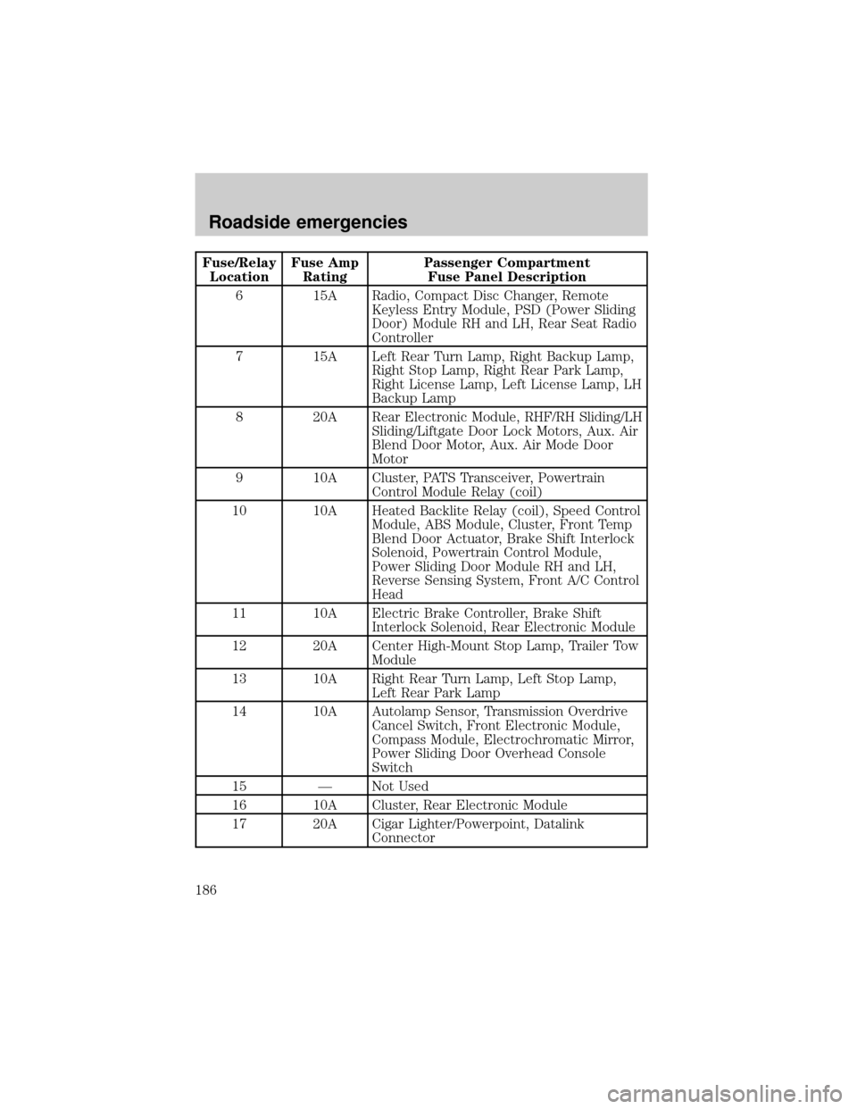
Fuse/Relay
LocationFuse Amp
RatingPassenger Compartment
Fuse Panel Description
6 15A Radio, Compact Disc Changer, Remote
Keyless Entry Module, PSD (Power Sliding
Door) Module RH and LH, Rear Seat Radio
Controller
7 15A Left Rear Turn Lamp, Right Backup Lamp,
Right Stop Lamp, Right Rear Park Lamp,
Right License Lamp, Left License Lamp, LH
Backup Lamp
8 20A Rear Electronic Module, RHF/RH Sliding/LH
Sliding/Liftgate Door Lock Motors, Aux. Air
Blend Door Motor, Aux. Air Mode Door
Motor
9 10A Cluster, PATS Transceiver, Powertrain
Control Module Relay (coil)
10 10A Heated Backlite Relay (coil), Speed Control
Module, ABS Module, Cluster, Front Temp
Blend Door Actuator, Brake Shift Interlock
Solenoid, Powertrain Control Module,
Power Sliding Door Module RH and LH,
Reverse Sensing System, Front A/C Control
Head
11 10A Electric Brake Controller, Brake Shift
Interlock Solenoid, Rear Electronic Module
12 20A Center High-Mount Stop Lamp, Trailer Tow
Module
13 10A Right Rear Turn Lamp, Left Stop Lamp,
Left Rear Park Lamp
14 10A Autolamp Sensor, Transmission Overdrive
Cancel Switch, Front Electronic Module,
Compass Module, Electrochromatic Mirror,
Power Sliding Door Overhead Console
Switch
15 Ð Not Used
16 10A Cluster, Rear Electronic Module
17 20A Cigar Lighter/Powerpoint, Datalink
Connector
Roadside emergencies
186