relay FORD WINDSTAR 2000 2.G Owners Manual
[x] Cancel search | Manufacturer: FORD, Model Year: 2000, Model line: WINDSTAR, Model: FORD WINDSTAR 2000 2.GPages: 280, PDF Size: 2.49 MB
Page 103 of 280

Safety/Obstructions
If anything obstructs the Power Sliding Door while it is closing, the door
will automatically reverse to the open position, provided it meets
sufficient resistance.
Resetting the PSD
The power sliding door may operate incorrectly or not at all because of
the following condition:
²a low voltage or dead battery
²disconnecting the battery
²if the PSD fuse (fuse #6) is removed or blown. Refer toFuses and
relaysin theRoadside emergencieschapter.
If any of these conditions occur, reset the PSD by:
1. Check to see if power sliding door is unlocked and securely closed.
2. Make sure the gearshift is in (P) Park.
3. Push the power door control on the overhead console to open the
door.
4. Wait five (5) seconds and close the door by pressing the power door
control on the overhead console.
5. Wait five (5) seconds and repeat Steps 3 and 4 and go on to step 6.
6. Repeat steps 3±5 for opposite door.
If the door does not rest in the fully open position, repeat Steps 1±4
again. If the door still does not operate correctly:
7. Turn the ignition switch to OFF.
8. Remove the PSD fuse (fuse #6) from the passenger fuse panel and
leave it out for thirty (30) seconds. Refer toFuses and relaysin the
Roadside emergencieschapter.
9. Reinstall the fuse and wait ten (10) seconds.
10. Repeat steps 1±6 above.
If the door still does not operate correctly, see your dealer for service.
Sliding Door Child Safety Lock
Your vehicle is equipped with a sliding door child safety lock that helps
prevent passengers from operating the sliding door by using the inside
door handle. This lock is on both doors if equipped. The child safety lock
Controls and features
103
Page 169 of 280
AUTOMATIC TRANSAXLE OPERATION
Brake-shift interlock
This vehicle is equipped with a brake-shift interlock feature that prevents
the gearshift lever from being moved from P (Park) unless the brake
pedal is depressed.
If the gearshift lever cannot be moved from P (Park) with the brake
pedal depressed, it is possible that a fuse has blown or the vehicle's
brakelamps are not operating properly. Refer toFuses and relaysin the
Roadside emergencieschapter.
Do not drive your vehicle until you verify that the brakelamps
are working.
If your vehicle gets stuck in mud or snow it may be rocked out by
shifting from forward and reverse gears, stopping between shifts, in a
steady pattern. Press lightly on the accelerator in each gear.
Do not rock the vehicle if the engine is not at normal operating
temperature or damage to the transaxle may occur.
Do not rock the vehicle for more than a few minutes or damage
to the transaxle and tires may occur or the engine may overheat.
Always set the parking brake fully and make sure the gearshift is
latched in P (Park). Turn off the ignition whenever you leave
your vehicle.
If the parking brake is fully released, but the brake warning lamp
remains illuminated, the brakes may not be working properly.
See your dealer or a qualified service technician.
Driving with an automatic overdrive transaxle with column
gearshift and O/D off switch
Your automatic transaxle electronically controls the shift feel by using an
adaptive learning strategy. This feature is designed to optimize shift
smoothness. It is normal for your transaxle to shift firmly during the first
few hundred kilometers (miles) of operation until the adaptive strategy
has been learned. The adaptive learning strategy is maintained by power
from the battery. When the battery is disconnected or a new battery is
Driving
169
Page 182 of 280
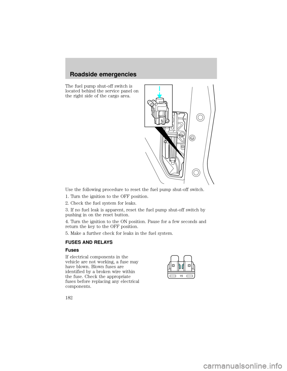
The fuel pump shut-off switch is
located behind the service panel on
the right side of the cargo area.
Use the following procedure to reset the fuel pump shut-off switch.
1. Turn the ignition to the OFF position.
2. Check the fuel system for leaks.
3. If no fuel leak is apparent, reset the fuel pump shut-off switch by
pushing in on the reset button.
4. Turn the ignition to the ON position. Pause for a few seconds and
return the key to the OFF position.
5. Make a further check for leaks in the fuel system.
FUSES AND RELAYS
Fuses
If electrical components in the
vehicle are not working, a fuse may
have blown. Blown fuses are
identified by a broken wire within
the fuse. Check the appropriate
fuses before replacing any electrical
components.
15
Roadside emergencies
182
Page 185 of 280
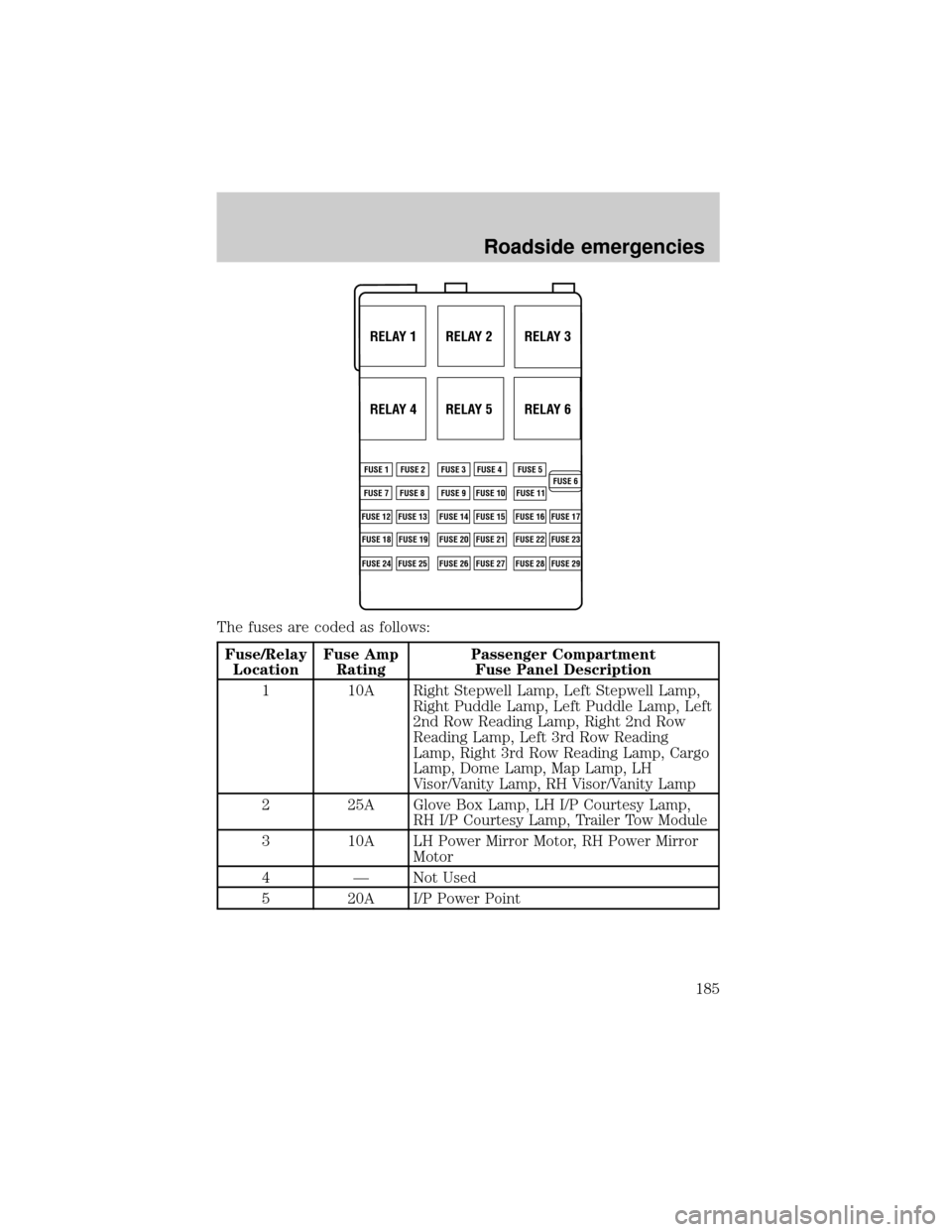
The fuses are coded as follows:
Fuse/Relay
LocationFuse Amp
RatingPassenger Compartment
Fuse Panel Description
1 10A Right Stepwell Lamp, Left Stepwell Lamp,
Right Puddle Lamp, Left Puddle Lamp, Left
2nd Row Reading Lamp, Right 2nd Row
Reading Lamp, Left 3rd Row Reading
Lamp, Right 3rd Row Reading Lamp, Cargo
Lamp, Dome Lamp, Map Lamp, LH
Visor/Vanity Lamp, RH Visor/Vanity Lamp
2 25A Glove Box Lamp, LH I/P Courtesy Lamp,
RH I/P Courtesy Lamp, Trailer Tow Module
3 10A LH Power Mirror Motor, RH Power Mirror
Motor
4 Ð Not Used
5 20A I/P Power Point
RELAY 1 RELAY 2 RELAY 3
RELAY 4 RELAY 5 RELAY 6
FUSE 1
FUSE 7
FUSE 12
FUSE 18
FUSE 24FUSE 8
FUSE 13
FUSE 19
FUSE 25FUSE 9
FUSE 14
FUSE 20
FUSE 26FUSE 10
FUSE 15
FUSE 21
FUSE 27FUSE 11
FUSE 16
FUSE 22
FUSE 28FUSE 17
FUSE 23
FUSE 29 FUSE 2 FUSE 3 FUSE 4 FUSE 5
FUSE 6
Roadside emergencies
185
Page 186 of 280
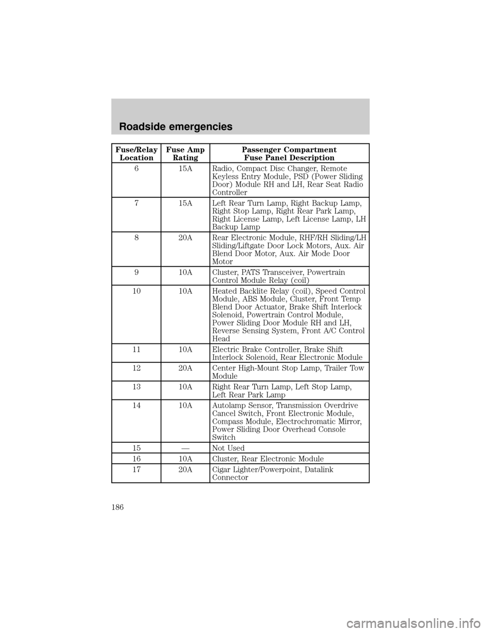
Fuse/Relay
LocationFuse Amp
RatingPassenger Compartment
Fuse Panel Description
6 15A Radio, Compact Disc Changer, Remote
Keyless Entry Module, PSD (Power Sliding
Door) Module RH and LH, Rear Seat Radio
Controller
7 15A Left Rear Turn Lamp, Right Backup Lamp,
Right Stop Lamp, Right Rear Park Lamp,
Right License Lamp, Left License Lamp, LH
Backup Lamp
8 20A Rear Electronic Module, RHF/RH Sliding/LH
Sliding/Liftgate Door Lock Motors, Aux. Air
Blend Door Motor, Aux. Air Mode Door
Motor
9 10A Cluster, PATS Transceiver, Powertrain
Control Module Relay (coil)
10 10A Heated Backlite Relay (coil), Speed Control
Module, ABS Module, Cluster, Front Temp
Blend Door Actuator, Brake Shift Interlock
Solenoid, Powertrain Control Module,
Power Sliding Door Module RH and LH,
Reverse Sensing System, Front A/C Control
Head
11 10A Electric Brake Controller, Brake Shift
Interlock Solenoid, Rear Electronic Module
12 20A Center High-Mount Stop Lamp, Trailer Tow
Module
13 10A Right Rear Turn Lamp, Left Stop Lamp,
Left Rear Park Lamp
14 10A Autolamp Sensor, Transmission Overdrive
Cancel Switch, Front Electronic Module,
Compass Module, Electrochromatic Mirror,
Power Sliding Door Overhead Console
Switch
15 Ð Not Used
16 10A Cluster, Rear Electronic Module
17 20A Cigar Lighter/Powerpoint, Datalink
Connector
Roadside emergencies
186
Page 187 of 280
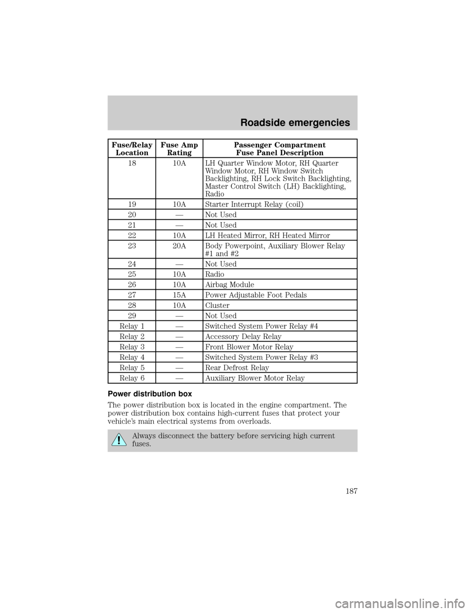
Fuse/Relay
LocationFuse Amp
RatingPassenger Compartment
Fuse Panel Description
18 10A LH Quarter Window Motor, RH Quarter
Window Motor, RH Window Switch
Backlighting, RH Lock Switch Backlighting,
Master Control Switch (LH) Backlighting,
Radio
19 10A Starter Interrupt Relay (coil)
20 Ð Not Used
21 Ð Not Used
22 10A LH Heated Mirror, RH Heated Mirror
23 20A Body Powerpoint, Auxiliary Blower Relay
#1 and #2
24 Ð Not Used
25 10A Radio
26 10A Airbag Module
27 15A Power Adjustable Foot Pedals
28 10A Cluster
29 Ð Not Used
Relay 1 Ð Switched System Power Relay #4
Relay 2 Ð Accessory Delay Relay
Relay 3 Ð Front Blower Motor Relay
Relay 4 Ð Switched System Power Relay #3
Relay 5 Ð Rear Defrost Relay
Relay 6 Ð Auxiliary Blower Motor Relay
Power distribution box
The power distribution box is located in the engine compartment. The
power distribution box contains high-current fuses that protect your
vehicle's main electrical systems from overloads.
Always disconnect the battery before servicing high current
fuses.
Roadside emergencies
187
Page 188 of 280
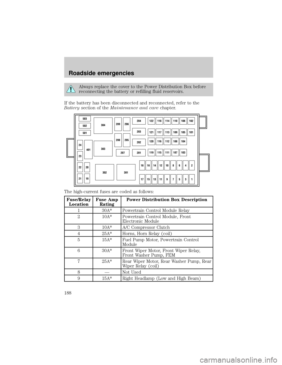
Always replace the cover to the Power Distribution Box before
reconnecting the battery or refilling fluid reservoirs.
If the battery has been disconnected and reconnected, refer to the
Batterysection of theMaintenance and carechapter.
The high-current fuses are coded as follows:
Fuse/Relay
LocationFuse Amp
RatingPower Distribution Box Description
1 30A* Powertrain Control Module Relay
2 10A* Powertrain Control Module, Front
Electronic Module
3 10A* A/C Compressor Clutch
4 25A* Horns, Horn Relay (coil)
5 15A* Fuel Pump Motor, Powertrain Control
Module
6 30A* Front Wiper Motor, Front Wiper Relay,
Front Washer Pump, FEM
7 25A* Rear Wiper Motor, Rear Washer Pump, Rear
Wiper Relay (coil)
8 Ð Not Used
9 15A* Right Headlamp (Low and High Beam)
503
304
303
302301
502
501
207201
202
203
204122118114110106102
121117113109105101
120116112108104
119115111107103
24
209206
208
18161412108642
1715131197531
205
23
22
21
401
20
19
Roadside emergencies
188
Page 189 of 280
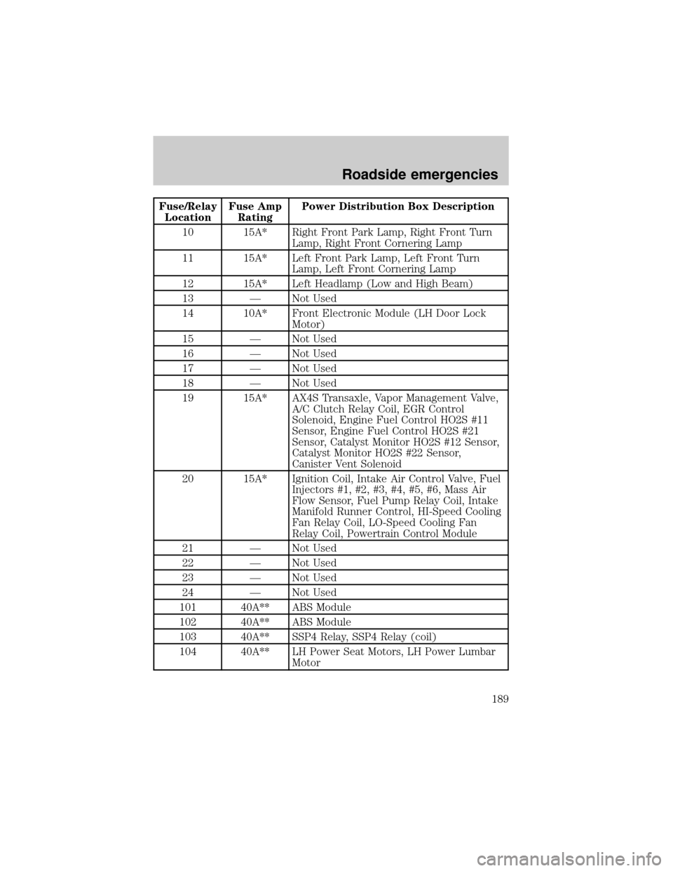
Fuse/Relay
LocationFuse Amp
RatingPower Distribution Box Description
10 15A* Right Front Park Lamp, Right Front Turn
Lamp, Right Front Cornering Lamp
11 15A* Left Front Park Lamp, Left Front Turn
Lamp, Left Front Cornering Lamp
12 15A* Left Headlamp (Low and High Beam)
13 Ð Not Used
14 10A* Front Electronic Module (LH Door Lock
Motor)
15 Ð Not Used
16 Ð Not Used
17 Ð Not Used
18 Ð Not Used
19 15A* AX4S Transaxle, Vapor Management Valve,
A/C Clutch Relay Coil, EGR Control
Solenoid, Engine Fuel Control HO2S #11
Sensor, Engine Fuel Control HO2S #21
Sensor, Catalyst Monitor HO2S #12 Sensor,
Catalyst Monitor HO2S #22 Sensor,
Canister Vent Solenoid
20 15A* Ignition Coil, Intake Air Control Valve, Fuel
Injectors #1, #2, #3, #4, #5, #6, Mass Air
Flow Sensor, Fuel Pump Relay Coil, Intake
Manifold Runner Control, HI-Speed Cooling
Fan Relay Coil, LO-Speed Cooling Fan
Relay Coil, Powertrain Control Module
21 Ð Not Used
22 Ð Not Used
23 Ð Not Used
24 Ð Not Used
101 40A** ABS Module
102 40A** ABS Module
103 40A** SSP4 Relay, SSP4 Relay (coil)
104 40A** LH Power Seat Motors, LH Power Lumbar
Motor
Roadside emergencies
189
Page 190 of 280
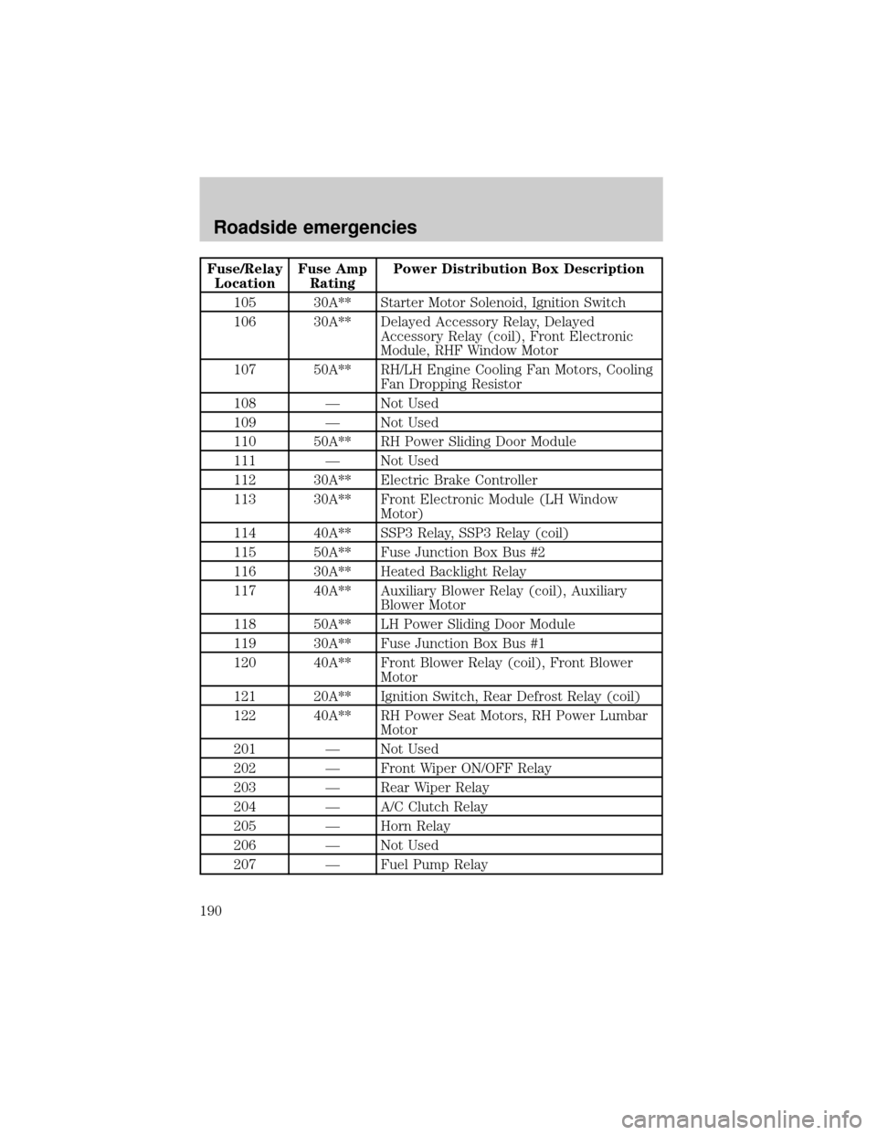
Fuse/Relay
LocationFuse Amp
RatingPower Distribution Box Description
105 30A** Starter Motor Solenoid, Ignition Switch
106 30A** Delayed Accessory Relay, Delayed
Accessory Relay (coil), Front Electronic
Module, RHF Window Motor
107 50A** RH/LH Engine Cooling Fan Motors, Cooling
Fan Dropping Resistor
108 Ð Not Used
109 Ð Not Used
110 50A** RH Power Sliding Door Module
111 Ð Not Used
112 30A** Electric Brake Controller
113 30A** Front Electronic Module (LH Window
Motor)
114 40A** SSP3 Relay, SSP3 Relay (coil)
115 50A** Fuse Junction Box Bus #2
116 30A** Heated Backlight Relay
117 40A** Auxiliary Blower Relay (coil), Auxiliary
Blower Motor
118 50A** LH Power Sliding Door Module
119 30A** Fuse Junction Box Bus #1
120 40A** Front Blower Relay (coil), Front Blower
Motor
121 20A** Ignition Switch, Rear Defrost Relay (coil)
122 40A** RH Power Seat Motors, RH Power Lumbar
Motor
201 Ð Not Used
202 Ð Front Wiper ON/OFF Relay
203 Ð Rear Wiper Relay
204 Ð A/C Clutch Relay
205 Ð Horn Relay
206 Ð Not Used
207 Ð Fuel Pump Relay
Roadside emergencies
190
Page 191 of 280
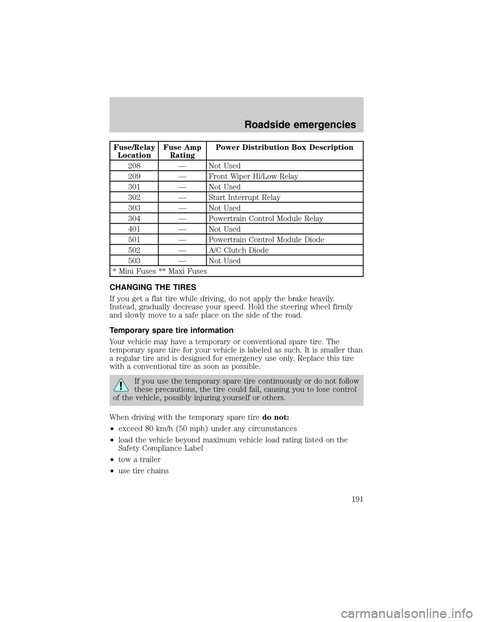
Fuse/Relay
LocationFuse Amp
RatingPower Distribution Box Description
208 Ð Not Used
209 Ð Front Wiper Hi/Low Relay
301 Ð Not Used
302 Ð Start Interrupt Relay
303 Ð Not Used
304 Ð Powertrain Control Module Relay
401 Ð Not Used
501 Ð Powertrain Control Module Diode
502 Ð A/C Clutch Diode
503 Ð Not Used
* Mini Fuses ** Maxi Fuses
CHANGING THE TIRES
If you get a flat tire while driving, do not apply the brake heavily.
Instead, gradually decrease your speed. Hold the steering wheel firmly
and slowly move to a safe place on the side of the road.
Temporary spare tire information
Your vehicle may have a temporary or conventional spare tire. The
temporary spare tire for your vehicle is labeled as such. It is smaller than
a regular tire and is designed for emergency use only. Replace this tire
with a conventional tire as soon as possible.
If you use the temporary spare tire continuously or do not follow
these precautions, the tire could fail, causing you to lose control
of the vehicle, possibly injuring yourself or others.
When driving with the temporary spare tiredo not:
²exceed 80 km/h (50 mph) under any circumstances
²load the vehicle beyond maximum vehicle load rating listed on the
Safety Compliance Label
²tow a trailer
²use tire chains
Roadside emergencies
191