battery FORD WINDSTAR 2001 2.G Owners Manual
[x] Cancel search | Manufacturer: FORD, Model Year: 2001, Model line: WINDSTAR, Model: FORD WINDSTAR 2001 2.GPages: 288, PDF Size: 2.6 MB
Page 5 of 288
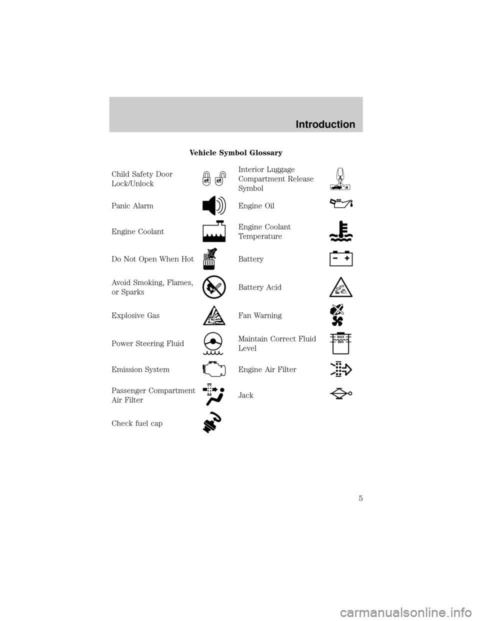
Vehicle Symbol Glossary
Child Safety Door
Lock/Unlock
Interior Luggage
Compartment Release
Symbol
Panic AlarmEngine Oil
Engine CoolantEngine Coolant
Temperature
Do Not Open When HotBattery
Avoid Smoking, Flames,
or SparksBattery Acid
Explosive GasFan Warning
Power Steering FluidMaintain Correct Fluid
LevelMAX
MIN
Emission SystemEngine Air Filter
Passenger Compartment
Air FilterJack
Check fuel cap
Introduction
5
Page 8 of 288
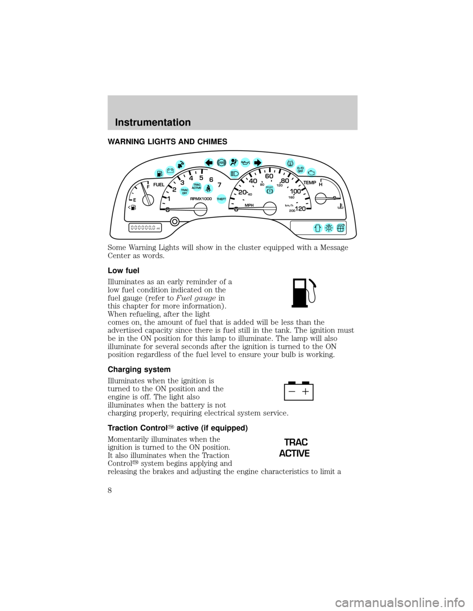
WARNING LIGHTS AND CHIMES
Some Warning Lights will show in the cluster equipped with a Message
Center as words.
Low fuel
Illuminates as an early reminder of a
low fuel condition indicated on the
fuel gauge (refer toFuel gaugein
this chapter for more information).
When refueling, after the light
comes on, the amount of fuel that is added will be less than the
advertised capacity since there is fuel still in the tank. The ignition must
be in the ON position for this lamp to illuminate. The lamp will also
illuminate for several seconds after the ignition is turned to the ON
position regardless of the fuel level to ensure your bulb is working.
Charging system
Illuminates when the ignition is
turned to the ON position and the
engine is off. The light also
illuminates when the battery is not
charging properly, requiring electrical system service.
Traction ControlYactive (if equipped)
Momentarily illuminates when the
ignition is turned to the ON position.
It also illuminates when the Traction
Controlysystem begins applying and
releasing the brakes and adjusting the engine characteristics to limit a
40
4080
120
160
20020
12345
6
760
80100
120MPH RPMX1000 THEFT
TRAC
ACTIVE TRAC
OFFTEMP
H
FFUEL
E
km/h
BRAKE
mi
O/D
OFF
TRAC
ACTIVE
Instrumentation
8
Page 28 of 288
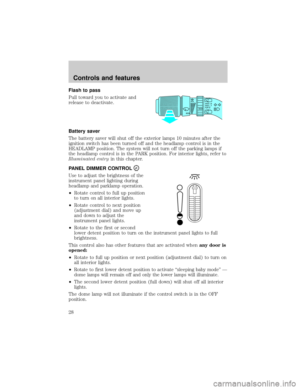
Flash to pass
Pull toward you to activate and
release to deactivate.
Battery saver
The battery saver will shut off the exterior lamps 10 minutes after the
ignition switch has been turned off and the headlamp control is in the
HEADLAMP position. The system will not turn off the parking lamps if
the headlamp control is in the PARK position. For interior lights, refer to
Illuminated entryin this chapter.
PANEL DIMMER CONTROL
Use to adjust the brightness of the
instrument panel lighting during
headlamp and parklamp operation.
²Rotate control to full up position
to turn on all interior lights.
²Rotate control to next position
(adjustment dial) and move up
and down to adjust the
instrument panel lights.
²Rotate to the first or second
lower detent position to turn on the instrument panel lights to full
brightness.
This control also has other features that are activated whenany door is
opened:
²Rotate to full up position or next position (adjustment dial) to turn on
all interior lights.
²
Rotate to first lower detent position to activate ªsleeping baby modeº Ð
dome lamps will remain off and only the lower lamps will illuminate.
²The second lower detent position (full down) will shut off all interior
lights.
The dome lamp will not illuminate if the control switch is in the OFF
position.
Controls and features
28
Page 100 of 288

Safety/Obstructions
If anything obstructs the Power Sliding Door while it is closing, the door
will automatically reverse to the open position, provided it meets
sufficient resistance.
Resetting the PSD
The power sliding door may operate incorrectly or not at all because of
the following condition:
²a low voltage or dead battery
²disconnecting the battery
²if the PSD fuse (fuse #6 ) is removed or blown. Refer toFuses and
relaysin theRoadside emergencieschapter.
If any of these conditions occur, reset the PSD by:
1. Check to see if power sliding door is unlocked and securely closed.
2. Make sure the gearshift is in (P) Park.
3.
Push the power door control on the overhead console to open the door.
4. Wait five (5) seconds and close the door by pressing the power door
control on the overhead console.
5. Wait five (5) seconds and repeat Steps 3 and 4 and go on to step 6.
6. Repeat steps 3±5 for opposite door.
If the door does not rest in the fully open position, repeat Steps 1±4
again. If the door still does not operate correctly:
7. Turn the ignition switch to OFF.
8. Remove the PSD fuse (fuse #6) from the passenger fuse panel and
leave it out for thirty (30) seconds. Refer toFuses and relaysin the
Roadside emergencieschapter.
9. Reinstall the fuse and wait ten (10) seconds.
10. Repeat steps 1±6 above.
If the door still does not operate correctly, see your dealer for service.
Sliding Door Child Safety Lock
Your vehicle is equipped with a sliding door child safety lock that helps
prevent passengers from operating the sliding door by using the inside
door handle. This lock is on both doors if equipped. The child safety lock
lever is located in the inside of the sliding door, on the front edge of the
door. Lift the control up to engage the child lock.
Controls and features
100
Page 107 of 288

Illuminated entry
The interior lights will illuminate when the remote entry Unlock or Panic
control is pressed with the doors closed or when unlocking or opening a
power sliding door (if equipped).
The system automatically turns off after 25 seconds or when the ignition
is turned to the RUN position. The panel dimmer control mustnotbe
set to the OFF position for the illuminated entry to operate.
The inside lights will not turn off if:
²they have been turned on with the instrument panel dimmer control
or
²any door is open.
The battery saver will shut off the interior lamps 30 minutes after the
last door is closed even if the panel dimmer control is left on.
Illuminated exit
The interior lights will illuminate when the key is removed from the
ignition. When the headlamp control is on the ªsleeping baby modeº, only
the lower interior lights will illuminate.
The system automatically turns off after 25 seconds. The panel dimmer
control mustnotbe set to the OFF position for the illuminated entry to
operate.
Replacing the battery
The remote transmitter is powered by one coin type three-volt lithium
battery CR2032 or equivalent. Typical operating range will allow you to
be up to 10 meters (33 feet) away from your vehicle. A decrease in
operating range can be caused by:
²weather conditions
²nearby radio towers
²structures around the vehicle
²other vehicles parked next to the vehicle
Controls and features
107
Page 108 of 288
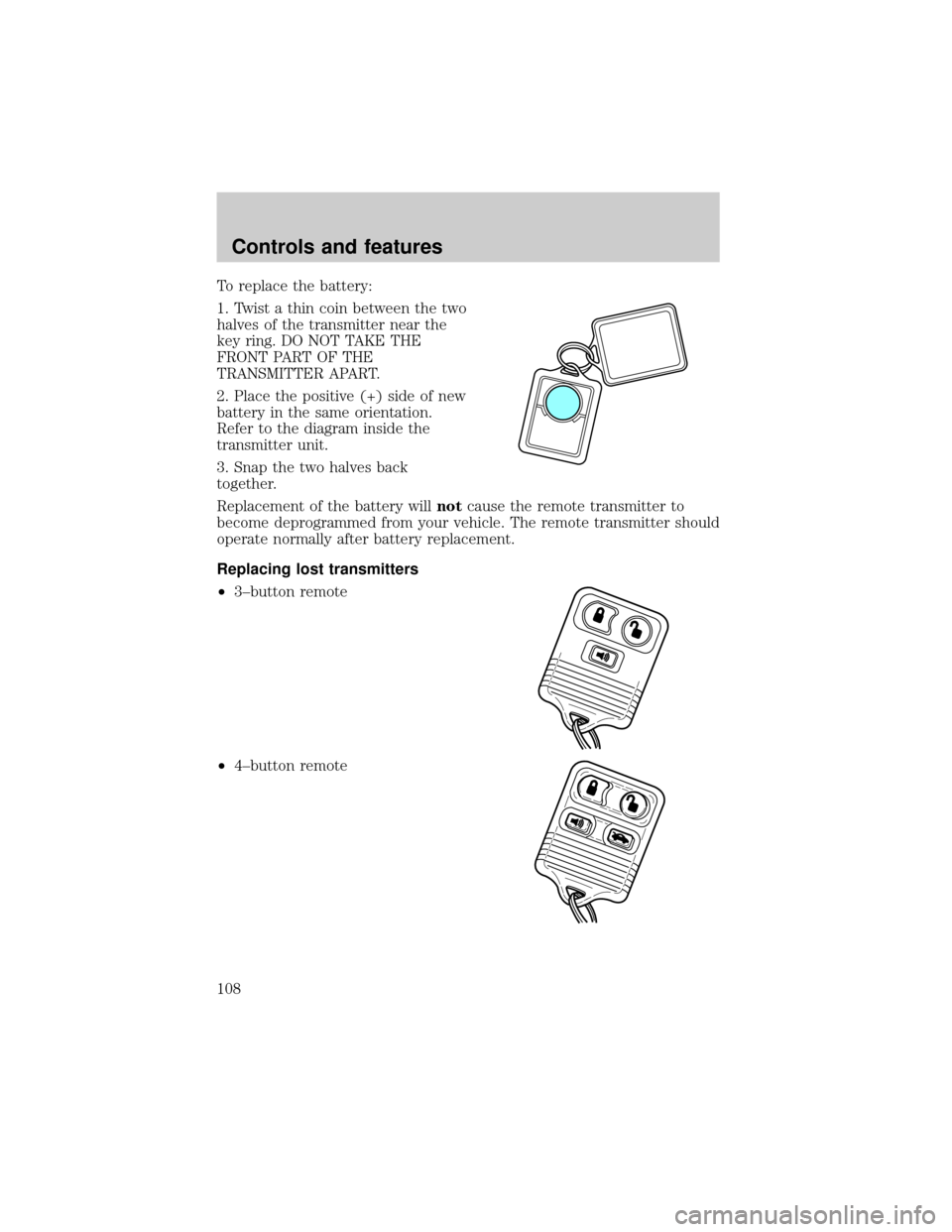
To replace the battery:
1. Twist a thin coin between the two
halves of the transmitter near the
key ring. DO NOT TAKE THE
FRONT PART OF THE
TRANSMITTER APART.
2. Place the positive (+) side of new
battery in the same orientation.
Refer to the diagram inside the
transmitter unit.
3. Snap the two halves back
together.
Replacement of the battery willnotcause the remote transmitter to
become deprogrammed from your vehicle. The remote transmitter should
operate normally after battery replacement.
Replacing lost transmitters
²3±button remote
²4±button remote
Controls and features
108
Page 174 of 288
If the gearshift lever cannot be moved from P (Park) with the brake
pedal depressed, it is possible that a fuse has blown or the vehicle's
brakelamps are not operating properly. Refer toFuses and relaysin the
Roadside emergencieschapter.
Do not drive your vehicle until you verify that the brakelamps
are working.
If your vehicle gets stuck in mud or snow it may be rocked out by
shifting between forward and reverse gears, stopping between shifts, in a
steady pattern. Press lightly on the accelerator in each gear.
Do not rock the vehicle if the engine is not at normal operating
temperature or damage to the transaxle may occur.
Do not rock the vehicle for more than a few minutes or damage
to the transaxle and tires may occur or the engine may overheat.
Always set the parking brake fully and make sure the gearshift is
latched in P (Park). Turn off the ignition whenever you leave
your vehicle.
If the parking brake is fully released, but the brake warning lamp
remains illuminated, the brakes may not be working properly.
See your dealer or a qualified service technician.
Driving with an automatic overdrive transaxle with column
gearshift and O/D off switch
Your automatic transaxle electronically controls the shift feel by using an
adaptive learning strategy. This feature is designed to optimize shift
smoothness. It is normal for your transaxle to shift firmly during the first
few hundred kilometers (miles) of operation until the adaptive strategy
has been learned. The adaptive learning strategy is maintained by power
from the battery. When the battery is disconnected or a new battery is
installed, the transaxle must relearn its adaptive strategy. Optimal
shifting will resume within a few hundred kilometers (miles) of
operation.
Driving
174
Page 175 of 288
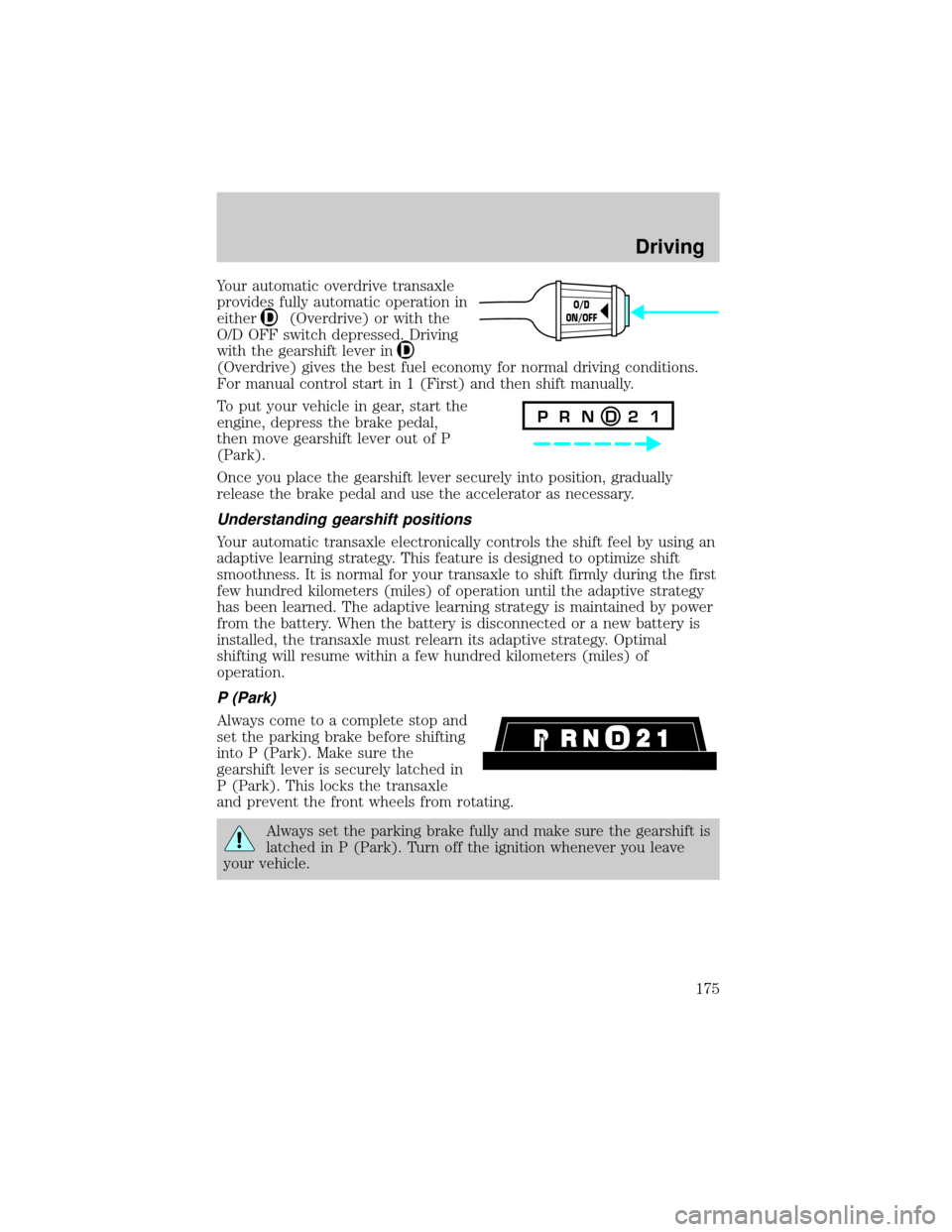
Your automatic overdrive transaxle
provides fully automatic operation in
either
(Overdrive) or with the
O/D OFF switch depressed. Driving
with the gearshift lever in
(Overdrive) gives the best fuel economy for normal driving conditions.
For manual control start in 1 (First) and then shift manually.
To put your vehicle in gear, start the
engine, depress the brake pedal,
then move gearshift lever out of P
(Park).
Once you place the gearshift lever securely into position, gradually
release the brake pedal and use the accelerator as necessary.
Understanding gearshift positions
Your automatic transaxle electronically controls the shift feel by using an
adaptive learning strategy. This feature is designed to optimize shift
smoothness. It is normal for your transaxle to shift firmly during the first
few hundred kilometers (miles) of operation until the adaptive strategy
has been learned. The adaptive learning strategy is maintained by power
from the battery. When the battery is disconnected or a new battery is
installed, the transaxle must relearn its adaptive strategy. Optimal
shifting will resume within a few hundred kilometers (miles) of
operation.
P (Park)
Always come to a complete stop and
set the parking brake before shifting
into P (Park). Make sure the
gearshift lever is securely latched in
P (Park). This locks the transaxle
and prevent the front wheels from rotating.
Always set the parking brake fully and make sure the gearshift is
latched in P (Park). Turn off the ignition whenever you leave
your vehicle.
O/D
ON/OFF
P R N D 2 1
Driving
175
Page 181 of 288
²Do not tow a trailer until your vehicle has been driven at least 800 km
(500 miles).
²Refer to the instructions included with towing accessories for the
proper installation and adjustment specifications.
If your vehicle is equipped with the optional heavy duty trailer tow
wiring, it is pre-wired for trailer towing. An electrical connector is
provided under the instrument panel for installing a customer-supplied
electric brake controller. Another electrical connector is provided at the
hitch. This connector provides power to the trailer for taillamps, stop
and turn lamps, back up lamps, battery charge, electric brakes (when a
customer provided controller is installed) and ground. The kit included
with your vehicle provides you with adaptors to attach the brake
controller and convert the hitch connector for Class I trailer usage.
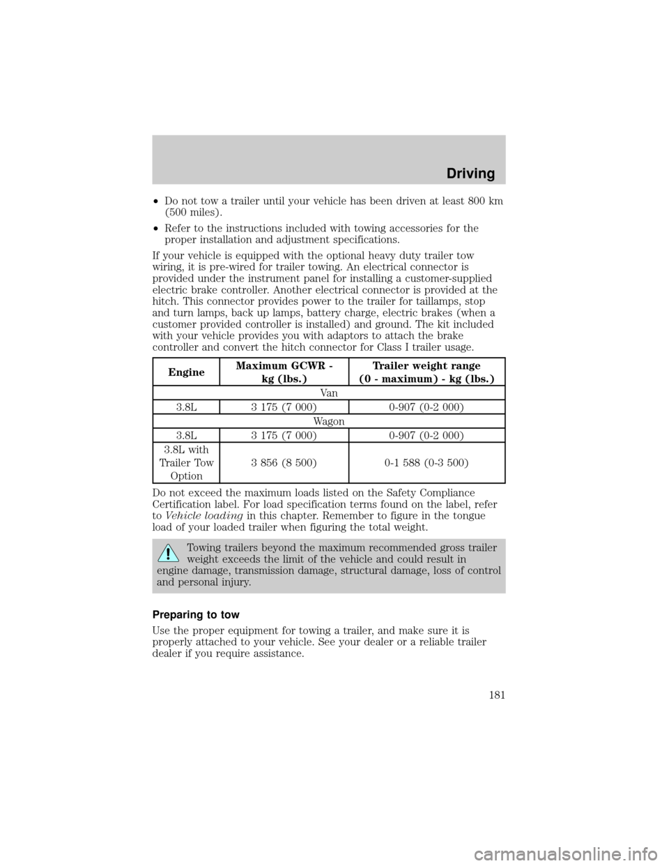
EngineMaximum GCWR -
kg (lbs.)Trailer weight range
(0 - maximum) - kg (lbs.)
Va n
3.8L 3 175 (7 000) 0-907 (0-2 000)
Wagon
3.8L 3 175 (7 000) 0-907 (0-2 000)
3.8L with
Trailer Tow
Option3 856 (8 500) 0-1 588 (0-3 500)
Do not exceed the maximum loads listed on the Safety Compliance
Certification label. For load specification terms found on the label, refer
toVehicle loadingin this chapter. Remember to figure in the tongue
load of your loaded trailer when figuring the total weight.
Towing trailers beyond the maximum recommended gross trailer
weight exceeds the limit of the vehicle and could result in
engine damage, transmission damage, structural damage, loss of control
and personal injury.
Preparing to tow
Use the proper equipment for towing a trailer, and make sure it is
properly attached to your vehicle. See your dealer or a reliable trailer
dealer if you require assistance.
Driving
181
Page 188 of 288
NOTE:Always replace a fuse with one that has the specified amperage
rating. Using a fuse with a higher amperage rating can cause severe wire
damage and could start a fire.
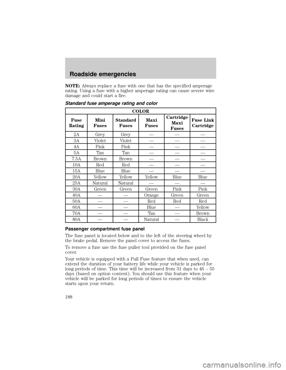
Standard fuse amperage rating and color
COLOR
Fuse
RatingMini
FusesStandard
FusesMaxi
FusesCartridge
Maxi
FusesFuse Link
Cartridge
2A Grey Grey Ð Ð Ð
3A Violet Violet Ð Ð Ð
4A Pink Pink Ð Ð Ð
5A Tan Tan Ð Ð Ð
7.5A Brown Brown Ð Ð Ð
10A Red Red Ð Ð Ð
15A Blue Blue Ð Ð Ð
20A Yellow Yellow Yellow Blue Blue
25A Natural Natural Ð Ð Ð
30A Green Green Green Pink Pink
40A Ð Ð Orange Green Green
50A Ð Ð Red Red Red
60A Ð Ð Blue Ð Yellow
70A Ð Ð Tan Ð Brown
80A Ð Ð Natural Ð Black
Passenger compartment fuse panel
The fuse panel is located below and to the left of the steering wheel by
the brake pedal. Remove the panel cover to access the fuses.
To remove a fuse use the fuse puller tool provided on the fuse panel
cover.
Your vehicle is equipped with a Pull Fuse feature that when used, can
extend the duration of your battery life while your vehicle is parked for
long periods of time. This time will be increased from 31 days to 45 ± 55
days (based on option content). You should use this feature when your
vehicle will be parked for long periods of times to ensure the vehicle
starts upon your return.
Roadside emergencies
188