oil FORD WINDSTAR 2001 2.G Owners Manual
[x] Cancel search | Manufacturer: FORD, Model Year: 2001, Model line: WINDSTAR, Model: FORD WINDSTAR 2001 2.GPages: 288, PDF Size: 2.6 MB
Page 5 of 288
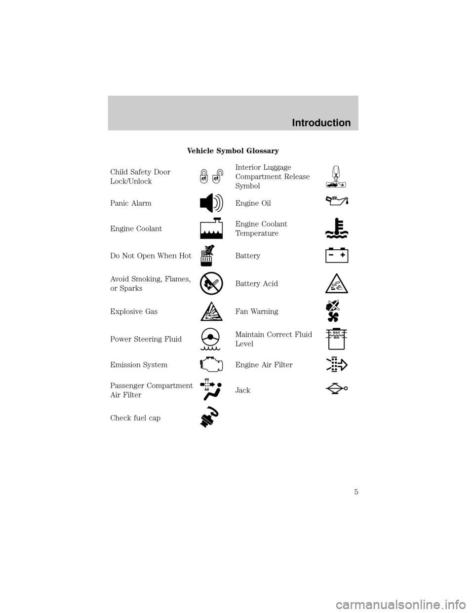
Vehicle Symbol Glossary
Child Safety Door
Lock/Unlock
Interior Luggage
Compartment Release
Symbol
Panic AlarmEngine Oil
Engine CoolantEngine Coolant
Temperature
Do Not Open When HotBattery
Avoid Smoking, Flames,
or SparksBattery Acid
Explosive GasFan Warning
Power Steering FluidMaintain Correct Fluid
LevelMAX
MIN
Emission SystemEngine Air Filter
Passenger Compartment
Air FilterJack
Check fuel cap
Introduction
5
Page 10 of 288
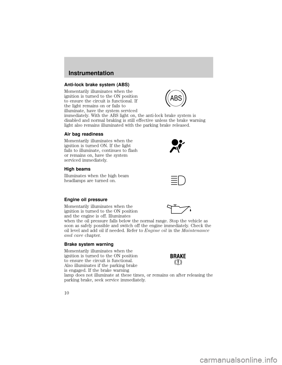
Anti-lock brake system (ABS)
Momentarily illuminates when the
ignition is turned to the ON position
to ensure the circuit is functional. If
the light remains on or fails to
illuminate, have the system serviced
immediately. With the ABS light on, the anti-lock brake system is
disabled and normal braking is still effective unless the brake warning
light also remains illuminated with the parking brake released.
Air bag readiness
Momentarily illuminates when the
ignition is turned ON. If the light
fails to illuminate, continues to flash
or remains on, have the system
serviced immediately.
High beams
Illuminates when the high beam
headlamps are turned on.
Engine oil pressure
Momentarily illuminates when the
ignition is turned to the ON position
and the engine is off. Illuminates
when the oil pressure falls below the normal range. Stop the vehicle as
soon as safely possible and switch off the engine immediately. Check the
oil level and add oil if needed. Refer toEngine oilin theMaintenance
and carechapter.
Brake system warning
Momentarily illuminates when the
ignition is turned to the ON position
to ensure the circuit is functional.
Also illuminates if the parking brake
is engaged. If the brake warning
lamp does not illuminate at these times, or remains on after releasing the
parking brake, seek service immediately.
ABS
!
BRAKE
Instrumentation
10
Page 18 of 288
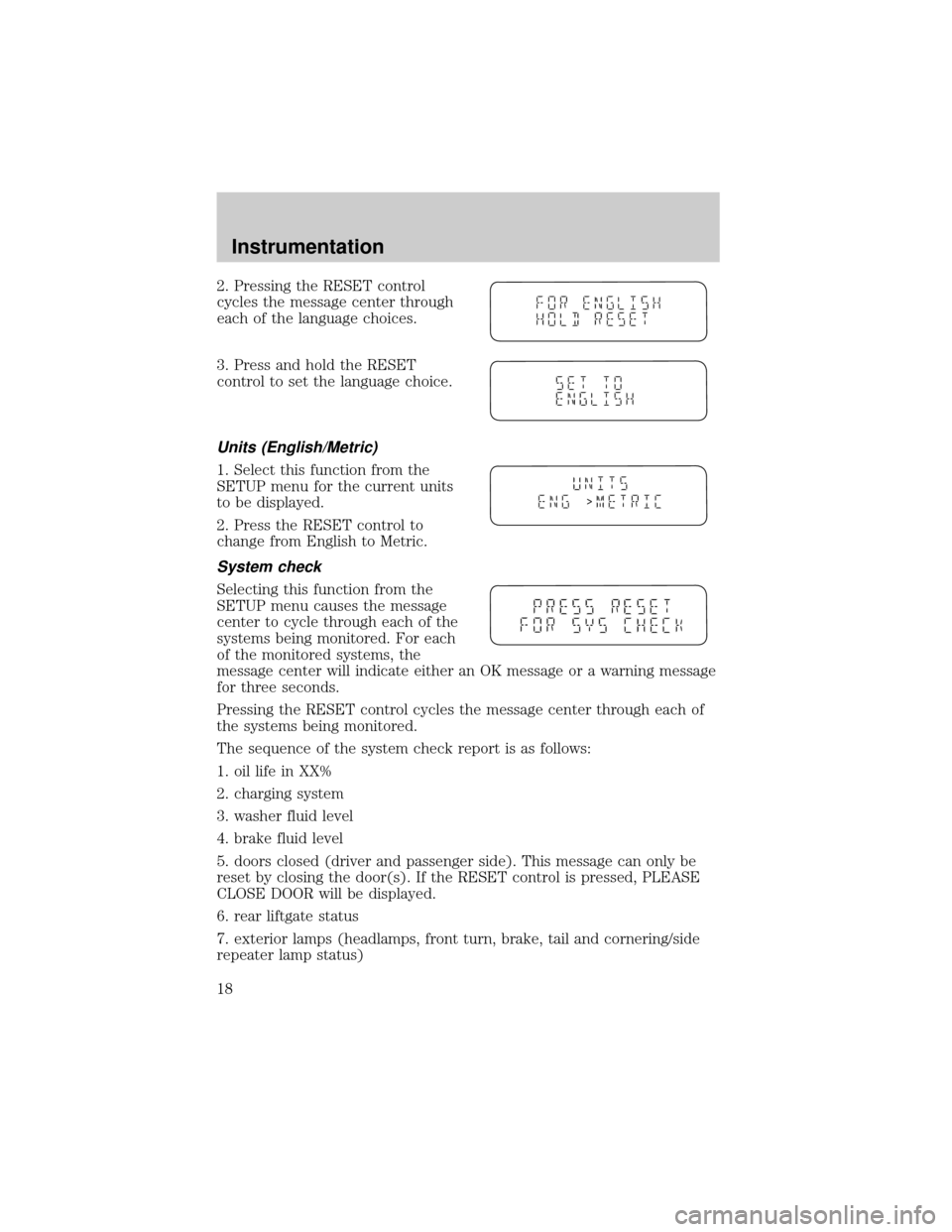
2. Pressing the RESET control
cycles the message center through
each of the language choices.
3. Press and hold the RESET
control to set the language choice.
Units (English/Metric)
1. Select this function from the
SETUP menu for the current units
to be displayed.
2. Press the RESET control to
change from English to Metric.
System check
Selecting this function from the
SETUP menu causes the message
center to cycle through each of the
systems being monitored. For each
of the monitored systems, the
message center will indicate either an OK message or a warning message
for three seconds.
Pressing the RESET control cycles the message center through each of
the systems being monitored.
The sequence of the system check report is as follows:
1. oil life in XX%
2. charging system
3. washer fluid level
4. brake fluid level
5. doors closed (driver and passenger side). This message can only be
reset by closing the door(s). If the RESET control is pressed, PLEASE
CLOSE DOOR will be displayed.
6. rear liftgate status
7. exterior lamps (headlamps, front turn, brake, tail and cornering/side
repeater lamp status)
>
Instrumentation
18
Page 20 of 288
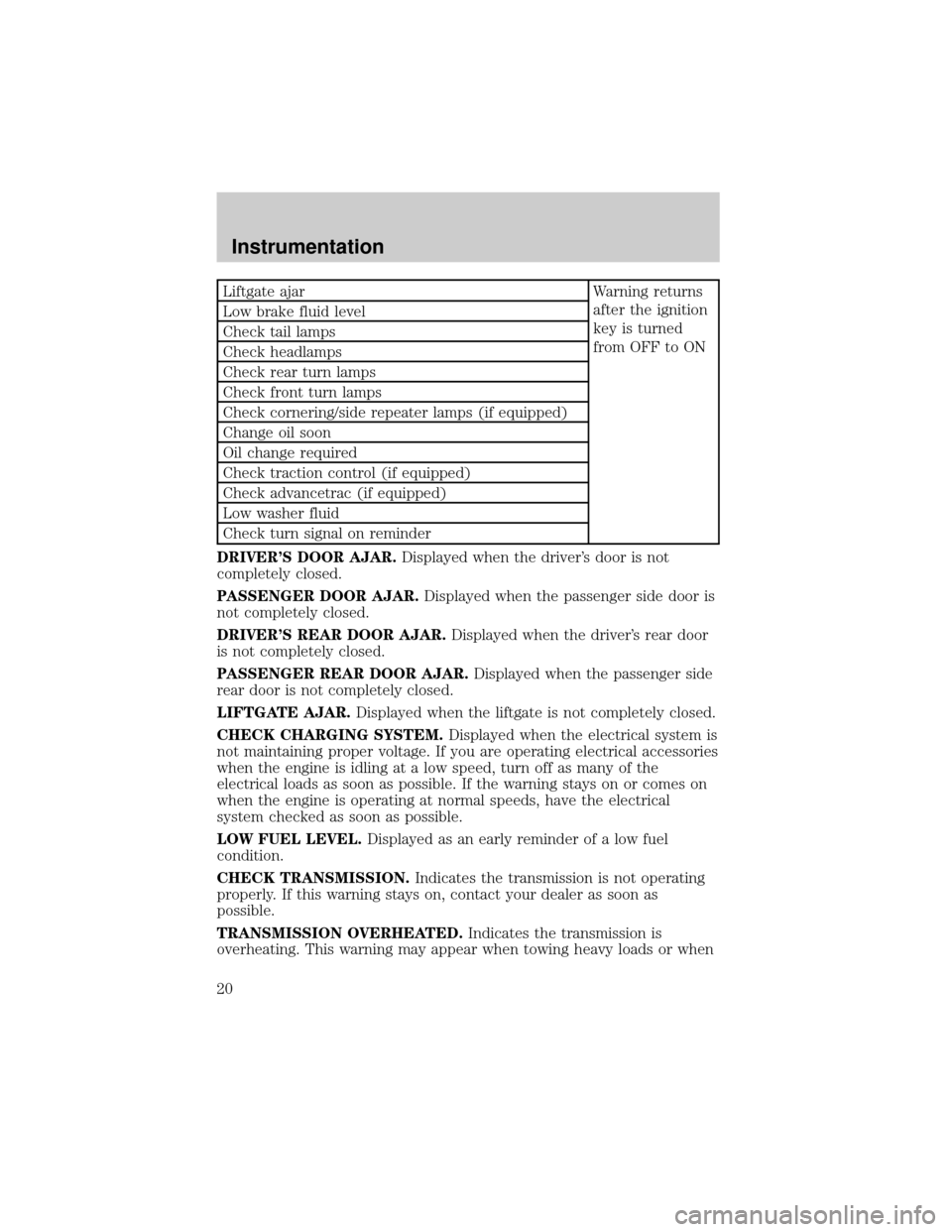
Liftgate ajar Warning returns
after the ignition
key is turned
from OFF to ON Low brake fluid level
Check tail lamps
Check headlamps
Check rear turn lamps
Check front turn lamps
Check cornering/side repeater lamps (if equipped)
Change oil soon
Oil change required
Check traction control (if equipped)
Check advancetrac (if equipped)
Low washer fluid
Check turn signal on reminder
DRIVER'S DOOR AJAR.Displayed when the driver's door is not
completely closed.
PASSENGER DOOR AJAR.Displayed when the passenger side door is
not completely closed.
DRIVER'S REAR DOOR AJAR.Displayed when the driver's rear door
is not completely closed.
PASSENGER REAR DOOR AJAR.Displayed when the passenger side
rear door is not completely closed.
LIFTGATE AJAR.Displayed when the liftgate is not completely closed.
CHECK CHARGING SYSTEM.Displayed when the electrical system is
not maintaining proper voltage. If you are operating electrical accessories
when the engine is idling at a low speed, turn off as many of the
electrical loads as soon as possible. If the warning stays on or comes on
when the engine is operating at normal speeds, have the electrical
system checked as soon as possible.
LOW FUEL LEVEL.Displayed as an early reminder of a low fuel
condition.
CHECK TRANSMISSION.Indicates the transmission is not operating
properly. If this warning stays on, contact your dealer as soon as
possible.
TRANSMISSION OVERHEATED.Indicates the transmission is
overheating. This warning may appear when towing heavy loads or when
Instrumentation
20
Page 22 of 288
partially operable. If this warning stays on while the engine is running,
contact your dealer for service as soon as possible. For further
information, refer toAdvanceTracystability enhancement systemin
theDrivingchapter.
CHANGE OIL SOON/OIL CHANGE REQUIRED.Displayed when the
engine oil life remaining is 5 percent or less. When oil life left is between
5% and 0%, the CHANGE OIL SOON message will be displayed. When oil
life left reaches 0%, the OIL CHANGE REQUIRED message will be
displayed.
An oil change is required whenever indicated by the message center.
USE ONLY RECOMMENDED ENGINE OILS.
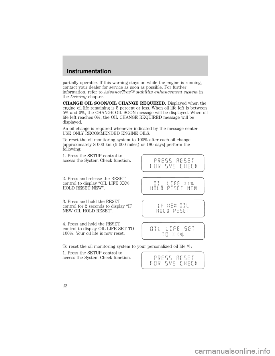
To reset the oil monitoring system to 100% after each oil change
[approximately 8 000 km (5 000 miles) or 180 days] perform the
following:
1. Press the SETUP control to
access the System Check function.
2. Press and release the RESET
control to display ªOIL LIFE XX%
HOLD RESET NEW''.
3. Press and hold the RESET
control for 2 seconds to display ªIF
NEW OIL HOLD RESET''.
4. Press and hold the RESET
control to display OIL LIFE SET TO
100%. Your oil life is now reset.
To reset the oil monitoring system to your personalized oil life %:
1. Press the SETUP control to
access the System Check function.
%
%
Instrumentation
22
Page 23 of 288
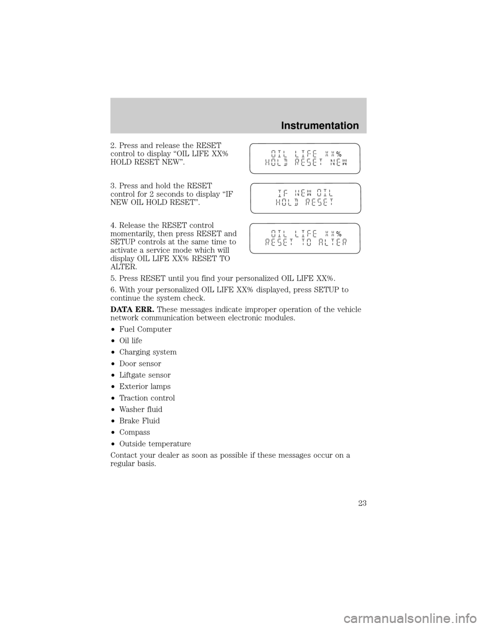
2. Press and release the RESET
control to display ªOIL LIFE XX%
HOLD RESET NEW''.
3. Press and hold the RESET
control for 2 seconds to display ªIF
NEW OIL HOLD RESET''.
4. Release the RESET control
momentarily, then press RESET and
SETUP controls at the same time to
activate a service mode which will
display OIL LIFE XX% RESET TO
ALTER.
5. Press RESET until you find your personalized OIL LIFE XX%.
6. With your personalized OIL LIFE XX% displayed, press SETUP to
continue the system check.
DATA ERR.These messages indicate improper operation of the vehicle
network communication between electronic modules.
²Fuel Computer
²Oil life
²Charging system
²Door sensor
²Liftgate sensor
²Exterior lamps
²Traction control
²Washer fluid
²Brake Fluid
²Compass
²Outside temperature
Contact your dealer as soon as possible if these messages occur on a
regular basis.
%
%
Instrumentation
23
Page 191 of 288
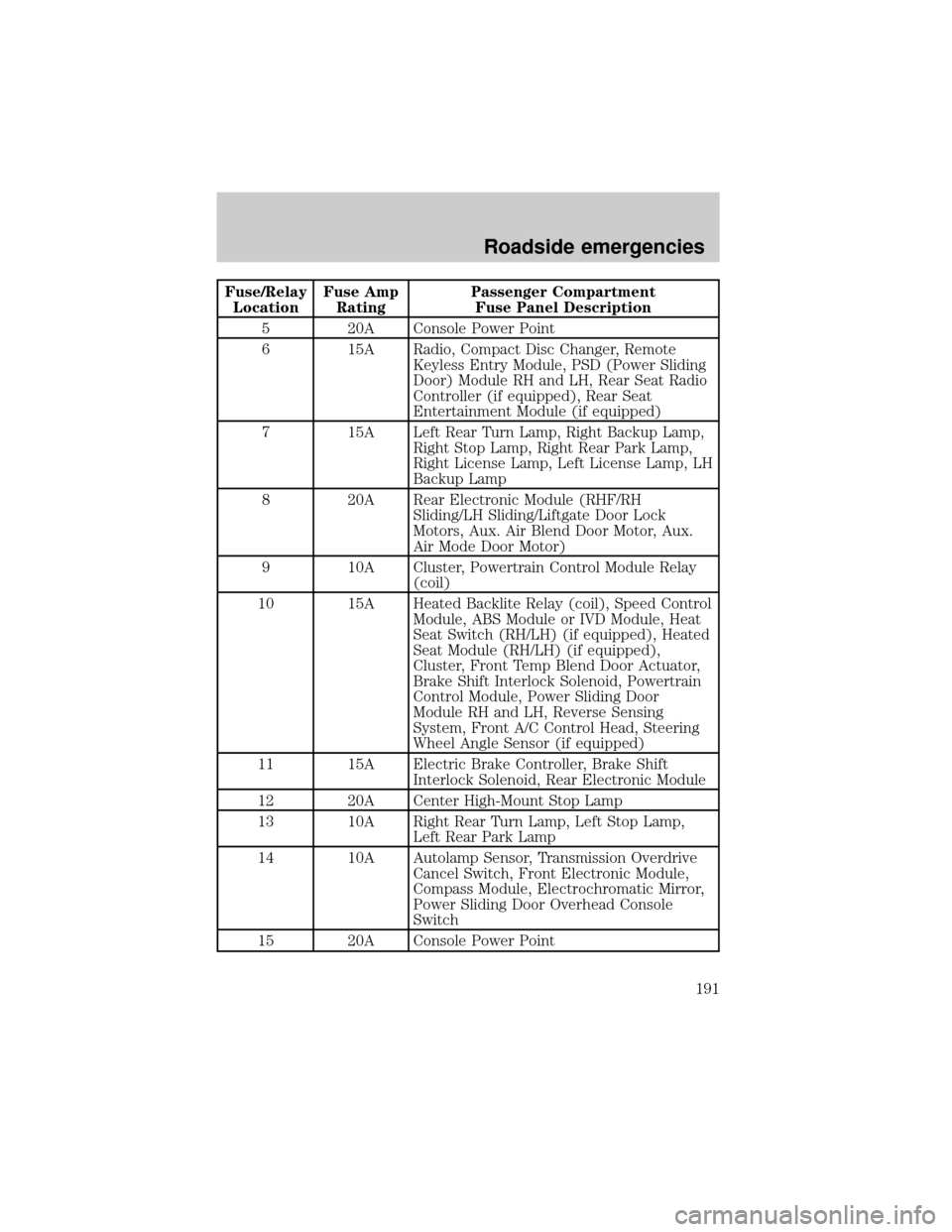
Fuse/Relay
LocationFuse Amp
RatingPassenger Compartment
Fuse Panel Description
5 20A Console Power Point
6 15A Radio, Compact Disc Changer, Remote
Keyless Entry Module, PSD (Power Sliding
Door) Module RH and LH, Rear Seat Radio
Controller (if equipped), Rear Seat
Entertainment Module (if equipped)
7 15A Left Rear Turn Lamp, Right Backup Lamp,
Right Stop Lamp, Right Rear Park Lamp,
Right License Lamp, Left License Lamp, LH
Backup Lamp
8 20A Rear Electronic Module (RHF/RH
Sliding/LH Sliding/Liftgate Door Lock
Motors, Aux. Air Blend Door Motor, Aux.
Air Mode Door Motor)
9 10A Cluster, Powertrain Control Module Relay
(coil)
10 15A Heated Backlite Relay (coil), Speed Control
Module, ABS Module or IVD Module, Heat
Seat Switch (RH/LH) (if equipped), Heated
Seat Module (RH/LH) (if equipped),
Cluster, Front Temp Blend Door Actuator,
Brake Shift Interlock Solenoid, Powertrain
Control Module, Power Sliding Door
Module RH and LH, Reverse Sensing
System, Front A/C Control Head, Steering
Wheel Angle Sensor (if equipped)
11 15A Electric Brake Controller, Brake Shift
Interlock Solenoid, Rear Electronic Module
12 20A Center High-Mount Stop Lamp
13 10A Right Rear Turn Lamp, Left Stop Lamp,
Left Rear Park Lamp
14 10A Autolamp Sensor, Transmission Overdrive
Cancel Switch, Front Electronic Module,
Compass Module, Electrochromatic Mirror,
Power Sliding Door Overhead Console
Switch
15 20A Console Power Point
Roadside emergencies
191
Page 192 of 288
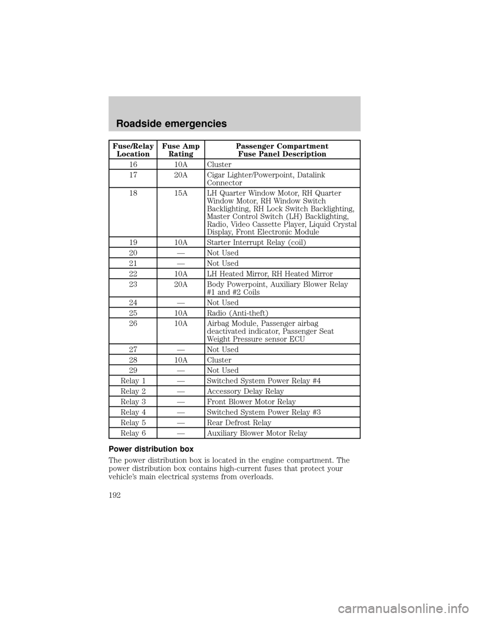
Fuse/Relay
LocationFuse Amp
RatingPassenger Compartment
Fuse Panel Description
16 10A Cluster
17 20A Cigar Lighter/Powerpoint, Datalink
Connector
18 15A LH Quarter Window Motor, RH Quarter
Window Motor, RH Window Switch
Backlighting, RH Lock Switch Backlighting,
Master Control Switch (LH) Backlighting,
Radio, Video Cassette Player, Liquid Crystal
Display, Front Electronic Module
19 10A Starter Interrupt Relay (coil)
20 Ð Not Used
21 Ð Not Used
22 10A LH Heated Mirror, RH Heated Mirror
23 20A Body Powerpoint, Auxiliary Blower Relay
#1 and #2 Coils
24 Ð Not Used
25 10A Radio (Anti-theft)
26 10A Airbag Module, Passenger airbag
deactivated indicator, Passenger Seat
Weight Pressure sensor ECU
27 Ð Not Used
28 10A Cluster
29 Ð Not Used
Relay 1 Ð Switched System Power Relay #4
Relay 2 Ð Accessory Delay Relay
Relay 3 Ð Front Blower Motor Relay
Relay 4 Ð Switched System Power Relay #3
Relay 5 Ð Rear Defrost Relay
Relay 6 Ð Auxiliary Blower Motor Relay
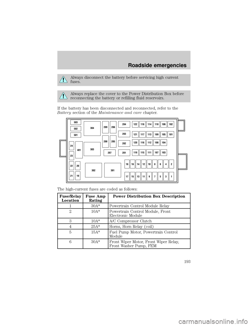
Power distribution box
The power distribution box is located in the engine compartment. The
power distribution box contains high-current fuses that protect your
vehicle's main electrical systems from overloads.
Roadside emergencies
192
Page 193 of 288
Always disconnect the battery before servicing high current
fuses.
Always replace the cover to the Power Distribution Box before
reconnecting the battery or refilling fluid reservoirs.
If the battery has been disconnected and reconnected, refer to the
Batterysection of theMaintenance and carechapter.
The high-current fuses are coded as follows:
Fuse/Relay
LocationFuse Amp
RatingPower Distribution Box Description
1 30A* Powertrain Control Module Relay
2 10A* Powertrain Control Module, Front
Electronic Module
3 10A* A/C Compressor Clutch
4 25A* Horns, Horn Relay (coil)
5 15A* Fuel Pump Motor, Powertrain Control
Module
6 30A* Front Wiper Motor, Front Wiper Relay,
Front Washer Pump, FEM
503
304
303
302301
502
501
207201
202
203
204122118114110106102
121117113109105101
120116112108104
119115111107103
24
209206
208
18161412108642
1715131197531
205
23
22
21
401
20
19
Roadside emergencies
193
Page 194 of 288
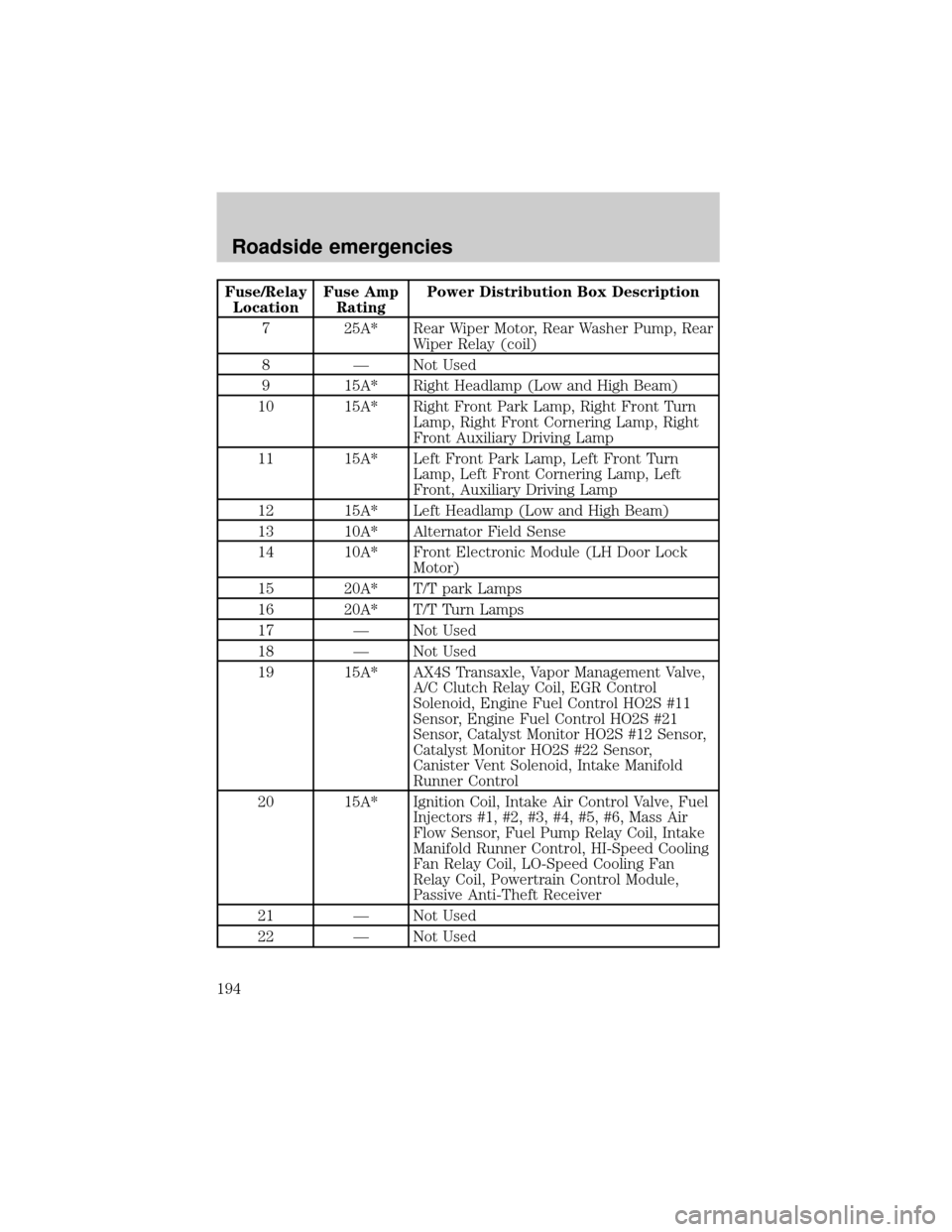
Fuse/Relay
LocationFuse Amp
RatingPower Distribution Box Description
7 25A* Rear Wiper Motor, Rear Washer Pump, Rear
Wiper Relay (coil)
8 Ð Not Used
9 15A* Right Headlamp (Low and High Beam)
10 15A* Right Front Park Lamp, Right Front Turn
Lamp, Right Front Cornering Lamp, Right
Front Auxiliary Driving Lamp
11 15A* Left Front Park Lamp, Left Front Turn
Lamp, Left Front Cornering Lamp, Left
Front, Auxiliary Driving Lamp
12 15A* Left Headlamp (Low and High Beam)
13 10A* Alternator Field Sense
14 10A* Front Electronic Module (LH Door Lock
Motor)
15 20A* T/T park Lamps
16 20A* T/T Turn Lamps
17 Ð Not Used
18 Ð Not Used
19 15A* AX4S Transaxle, Vapor Management Valve,
A/C Clutch Relay Coil, EGR Control
Solenoid, Engine Fuel Control HO2S #11
Sensor, Engine Fuel Control HO2S #21
Sensor, Catalyst Monitor HO2S #12 Sensor,
Catalyst Monitor HO2S #22 Sensor,
Canister Vent Solenoid, Intake Manifold
Runner Control
20 15A* Ignition Coil, Intake Air Control Valve, Fuel
Injectors #1, #2, #3, #4, #5, #6, Mass Air
Flow Sensor, Fuel Pump Relay Coil, Intake
Manifold Runner Control, HI-Speed Cooling
Fan Relay Coil, LO-Speed Cooling Fan
Relay Coil, Powertrain Control Module,
Passive Anti-Theft Receiver
21 Ð Not Used
22 Ð Not Used
Roadside emergencies
194