weight GEELY FC 2008 Workshop Manual
[x] Cancel search | Manufacturer: GEELY, Model Year: 2008, Model line: FC, Model: GEELY FC 2008Pages: 419, PDF Size: 13.87 MB
Page 12 of 419

Brief introduction on Geely model “FC”Basic parametersTable 1 Complete vehicle basic parametersUnit
Item nameNumber
Dimension parametersOverall
dimension
Wheel trackLength
Width
Height
Front wheel
Rear wheel
Wheel base
Front suspension
Rear suspensionPassenger numberPersonParameters±15±15±20±10±10±30±30Left lamp
Right lamp
Left lamp
Right lampLeft and
right
inclination
Down
inclinationComplete vehicle herb massMax. total massFront axle
Rear axle
Front axle
Rear axle
Weight distributionNo
load
Full
loadMin. turning diameter
Min. gound clearance
Approach angle (full load) Departure angle (full load)Front wheel camber
Kingpin inclination angle
caster angleConvergence of front wheelsRear wheel camberConvergence of rear wheelsLeft wheel: inside/outside
Right wheel:inside/outside CanderaBrief introduction on Geely model “FC” Basic parameters
Mass parameters
Traverse ability
Front wheel alignment
parameters
Rear wheel
alignment
parameters Front wheel
steering
wheel
Head lamp light
High beam
optical axisLuminous intensity of
high beam of head lamp1
Page 14 of 419

Brief introduction on Geely model “FC” Basic parametersTable 3 Main performance parameters of complete vehicle
UnitNumberParametersRemarksMax. vehicle speed
0-100 km/h accelerating timeAccelerating time from 30km/h to 100km/h at 4th gearMin. stable vehicle speed at 4th gear
Max. climbing speedSlide Distance (full-load, initial speed 50km/h)Fuel consumption with 4 operating modesAverage fuel consumption at specified operating modeDust sealing degree
Rain protection seal limit valueWeighted acceleration root of mean squareEquivalent mean value
Reduced comfort boundary
Average mileage to first failure
Average mileage between failures
Efficient degree Item name
Power performance 3
Economy
performance Seal
perfor-
mance
Ride
perfor-
mance
Reliability
Page 125 of 419

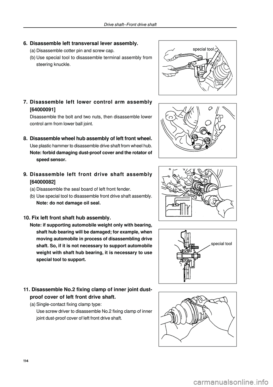
6. Disassemble left transversal lever assembly.(a) Disassemble cotter pin and screw cap.
(b) Use special tool to disassemble terminal assembly from
steering knuckle.7. Disassemble left lower control arm assembly
[64000091]Disassemble the bolt and two nuts, then disassemble lower
control arm from lower ball joint.8. Disassemble wheel hub assembly of left front wheel.Use plastic hammer to disassemble drive shaft from wheel hub.
Note: forbid damaging dust-proof cover and the rotator of
speed sensor.9. Disassemble left front drive shaft assembly
[64000082](a) Disassemble the seal board of left front fender.
(b) Use special tool to disassemble front drive shaft assembly.
Note: do not damage oil seal.10. Fix left front shaft hub assembly.Note: if supporting automobile weight only with bearing,
shaft hub bearing will be damaged; for example, when
moving automobile in process of disassembling drive
shaft. So, if it is not necessary to support automobile
weight with shaft hub bearing, it is necessary to use
special tool to support.11. Disassemble No.2 fixing clamp of inner joint dust-
proof cover of left front drive shaft.(a) Single-contact fixing clamp type:
Use screw driver to disassemble No.2 fixing clamp of inner
joint dust-proof cover of left front drive shaft.Drive shaft--Front drive shaftspecial toolspecial tool114