diagram GEELY MK 2008 Workshop Manual
[x] Cancel search | Manufacturer: GEELY, Model Year: 2008, Model line: MK, Model: GEELY MK 2008Pages: 416, PDF Size: 25.19 MB
Page 3 of 416
Geely “MK” series sedans (JL7132U,JL7132HU,JL7152U,JL7152HU,JL7162U) are brand
new superior models developed by Geely Group who has fully proprietary intellectual property
rights. As a result of the three years of involvements and efforts of the experts from Geely Automo-
bile Research Institute, these sedans reach international leading level in model design, power,
sense of comfort, safety and manufacturing technology while featured in beautiful appearance,
economy, environment protection and safety. The meaning of MK implied that Geely Automobile
has a great development from caterpillar to butterfly. With respect to the power, Geely “MK” series
sedans are equipped with 1.3L, 1.5L, and 1.6L EFI engines developed and manufactured by Geely
itself, and has reached “Chinese III” (Euro III) emission standard.
This manual contains a detailed description of the structures and principles, servicing and adjustment,
removal, assembling technology and matching clearance of the parts of the Geely “MK” sedans
with torque information of the bolts and nuts as well as schematic diagram for special tool operation.
This manual also introduces the transmission control system of the automatic transmission models,
vehicle electric circuits and elaborates ABS system, SRS, BOSCH M7.9.7 electronic control fuel
injection and ignition system, rear parking radar, sound, air conditioning and onboard hands-free
phone system. You can refer to this manual for the information about the regular maintenance,
servicing, adjustment, troubleshooting, removal and installation procedure, specific operations of
the “MK” sedans.
This manual covers the matching relation among the engine assembly, transmission assembly and
the vehicle, but does not have the further description of the structures and principles of the engine
and transmission assemblies and their servicing process. You can refer to the service manuals
solely prepared for engine assembly and transmission assembly for these information.
All information in this manual is based on the latest products released at the time of publication of
this manual. However, the specifications and procedures may need to be modified, and the subse-
quent change will be revealed in later versions.
This manual is prepared by Geely Automobile Research Institute under the assistance of technical
staff from Zhejiang Geely Automobile Co., Ltd and Geely International Corporation. Readers
discovering during the use of this manual the errors and careless omissions due to limited skills of
the preparers and tight schedule are encouraged and pled to contact Geely International in time for
our timely correction of the mistakes.ForewordGeely International Corporation
Nov . 2007
Page 7 of 416
Table of Contents IV Section 7 Rear Brake Drum ............................................................................................ 4-99
Section 8 Parking Brake System.......................................................................................4-106Part V Electric System & AccessoryChapter 1 Starting and Charging System......................................................................... 5-1
Section 1 Starting System (MR479Q, MR479QA, MR481QA) ...................................... 5-1
Section 2 Charging System (MR479Q, MR479QA, MR481QA) .................................... 5-3
Chapter 2 Combination Instrument System..................................................................... 5-7
Section 1 Wiring diagram of Combination Instrument and Location of Multi-pin Plug-in Terminal5-7
Section 2 Malfunction Symptom Table and Troubleshooting ......................................... 5-10
Chapter 3 Wiper and Washer System............................................................................... 5-21
Section 1 Wiper and Washer System Inspection ........................................................... 5-21
Section 2 Replacement and Adjustment ........................................................................ 5-23
Chapter 4 Light System...................................................................................................... 5-26
Section 1 Light System Introduction ............................................................................... 5-26
Section 2 Light System Malfunction Inspection ............................................................. 5-28
Section 3 Headlamp Replacement ................................................................................. 5-34
Section 4 Front Fog Lamp Replacement ...................................................................... 5-35
Section 5 Rear Combination Lamp Replacement .......................................................... 5-36
Section 6 High-mounted Stop light Replacement .......................................................... 5-36
Section 7 Front Reading Lamp Replacement ................................................................ 5-37
Section 8 Rear Reading Lamp Replacement ................................................................. 5-37
Section 9 License Plate Lamp Replacement ................................................................. 5-37
Chapter 5 Audio System..................................................................................................... 5-38
Section 1 Audio System Description .............................................................................. 5-38
Section 2 Audio System Connector Terminal Layout ..................................................... 5-40
Section 3 Audio System Inspection ................................................................................ 5-41
Section 4 Audio System Replacement ........................................................................... 5-52
Chapter 6 SRS (Supplemental Restraint System)............................................................ 5-54
Page 189 of 416
Starting and Charging System-
Starting System5-23. WiringII. Starter assembly replacement (MR479Q, MR479QA, MR481QA)1. Remove starter assembly
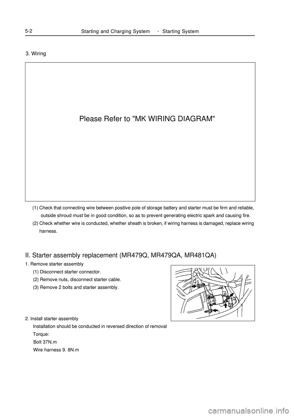
(1) Disconnect starter connector.
(2) Remove nuts, disconnect starter cable.
(3) Remove 2 bolts and starter assembly.
2. Install starter assembly
Installation should be conducted in reversed direction of removal
Torque:
Bolt 37N.m
Wire harness 9. 8N.m (1) Check that connecting wire between positive pole of storage battery and starter must be firm and reliable,
outside shroud must be in good condition, so as to prevent generating electric spark and causing fire.
(2) Check whether wire is conducted, whether sheath is broken, if wiring harness is damaged, replace wiring
harness.Please Refer to "MK WIRING DIAGRAM"
Page 194 of 416
Chapter 2 Combination Instrument SystemSection 1 Wiring diagram of Combination Instrument and
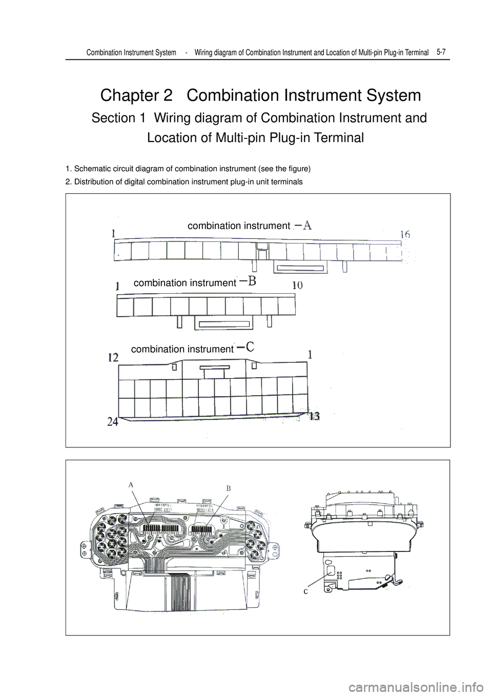
Location of Multi-pin Plug-in Terminal1. Schematic circuit diagram of combination instrument (see the figure)
2. Distribution of digital combination instrument plug-in unit terminalsCombination Instrument System -Wiring diagram of Combination Instrument and Location of Multi-pin Plug-in Terminal5-7combination instrument
combination instrument
combination instrument
Page 195 of 416
Combination Instrument System -Wiring diagram of Combination Instrument and Location of Multi-pin Plug-in Terminal5-8Please Refer to "MK WIRING DIAGRAM"Wiring diagram of Combination Instrument
Page 196 of 416
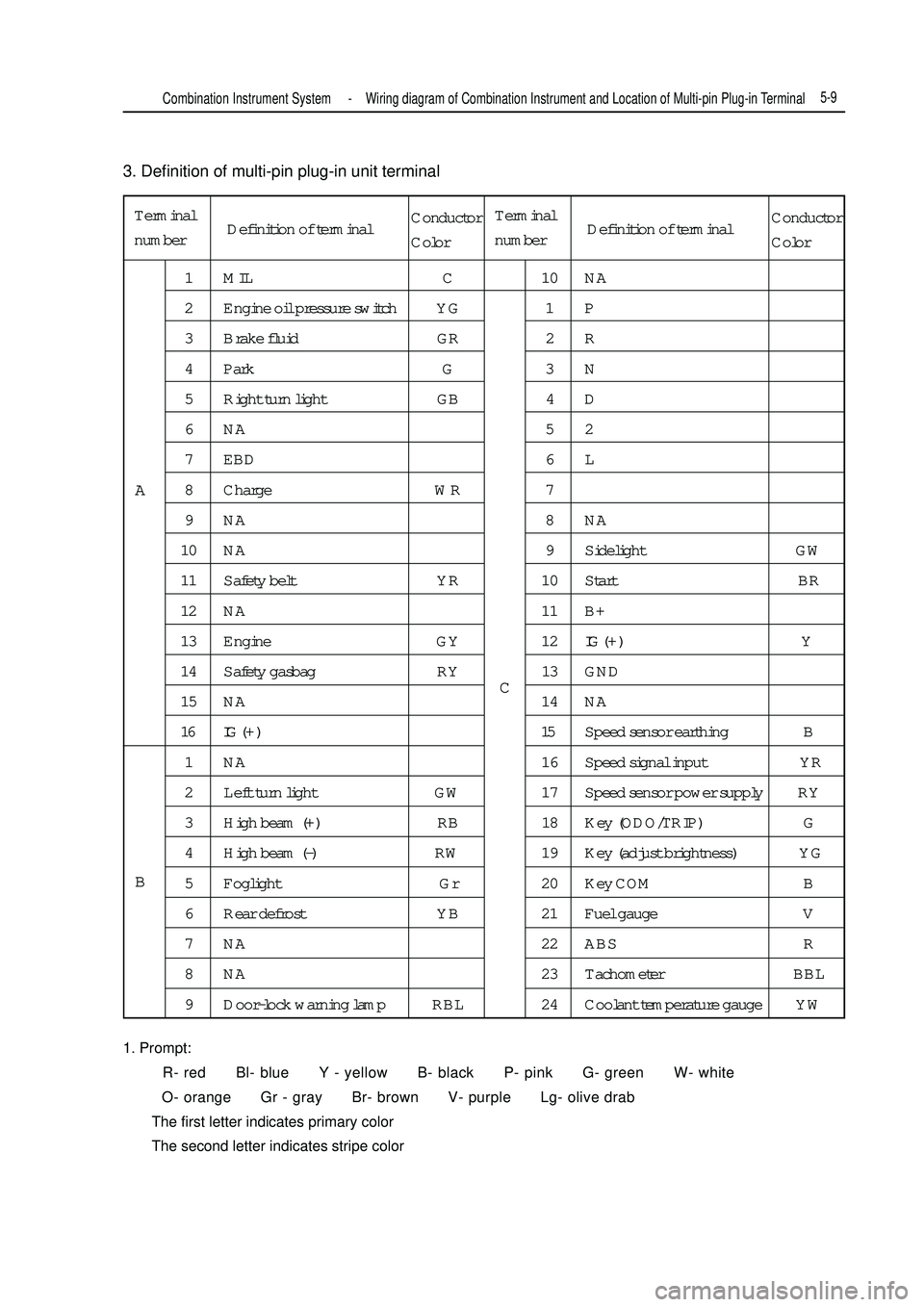
3. Definition of multi-pin plug-in unit terminal
1. Prompt:
R- red Bl- blue Y - yellow B- black P- pink G- green W- white
O- orange Gr - gray Br- brown V- purple Lg- olive drab
The first letter indicates primary color
The second letter indicates stripe colorTerminal
number1 MIL C 10 NA
2 Engine oil pressure switch YG 1 P
3 Brake fluid GR 2 R
4 Park G 3 N
5 Right turn light GB 4 D
6NA 52
7 EBD 6 L
8 Charge WR 7
9NA 8NA
10 NA 9 Sidelight GW
11 Safety belt YR 10 Start BR
12 NA 11 B+
13 Engine GY 12IG ( + ) Y
14 Safety gasbag RY 13 GND
15 NA 14 NA
16 IG ( + ) 15Speed sensor earthing B
1 NA 16 Speed signal input YR
2 Left turn light GW 17 Speed sensor power supply RY
3 High beam (+) RB 18 Key (ODO/TRIP) G
4 High beam (-) RW 19 Key (adjust brightness) YG
5 Foglight Gr 20 Key COM B
6 Rear defrost YB 21 Fuel gauge V
7 NA 22 ABS R
8 NA 23 Tachometer BBL
9 Door-lock warning lamp RBL 24 Coolant temperature gauge YWA
BCCombination Instrument System -Wiring diagram of Combination Instrument and Location of Multi-pin Plug-in Terminal5-9Definition of terminalConductor
ColorTerminal
numberDefinition of terminalConductor
Color
Page 197 of 416
Serial No. Symptom
1 The whole combination meter does not work
2 Speedometer fault
3 Tachometer fault
4 Water temperature gauge fault
5 Fuel gauge fault
6 Odometer fault
7 Instrument illumination fault
8 Instrument warning light fault
Tester connection Condition Standard condition
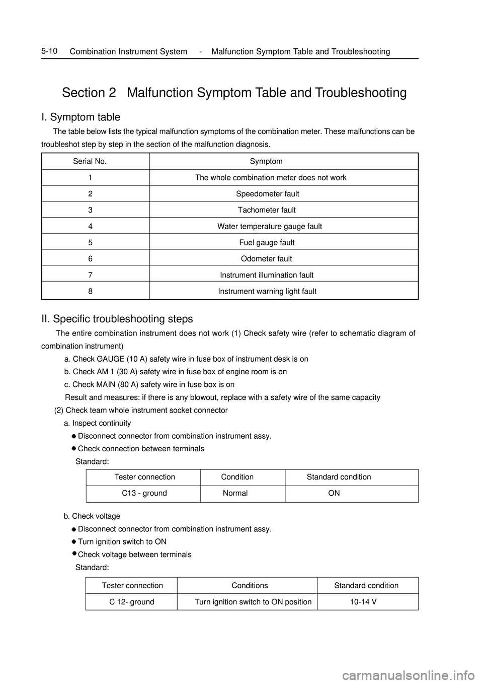
C13 - ground Normal ONSection 2 Malfunction Symptom Table and TroubleshootingI. Symptom table The table below lists the typical malfunction symptoms of the combination meter. These malfunctions can be
troubleshot step by step in the section of the malfunction diagnosis.Tester connection Conditions Standard condition
C 12- ground Turn ignition switch to ON position 10-14 VCombination Instrument System -Malfunction Symptom Table and Troubleshooting5-10II. Specific troubleshooting steps The entire combination instrument does not work (1) Check safety wire (refer to schematic diagram of
combination instrument)
a. Check GAUGE (10 A) safety wire in fuse box of instrument desk is on
b. Check AM 1 (30 A) safety wire in fuse box of engine room is on
c. Check MAIN (80 A) safety wire in fuse box is on
Result and measures: if there is any blowout, replace with a safety wire of the same capacity
(2) Check team whole instrument socket connector
a. Inspect continuity
Disconnect connector from combination instrument assy.
Check connection between terminals
Standard:
b. Check voltage
Disconnect connector from combination instrument assy.
Turn ignition switch to ON
Check voltage between terminals
Standard:
Page 200 of 416
5-13 c. Check voltage between terminals
Standard:Tester connectionConditions Standard condition
C 12- ground Turn ignition switch to ON position 7. 5-9V
Result and measures:
Abnormal, repair or replace wiring harness or connector
Normal, replace combination instrument assy.
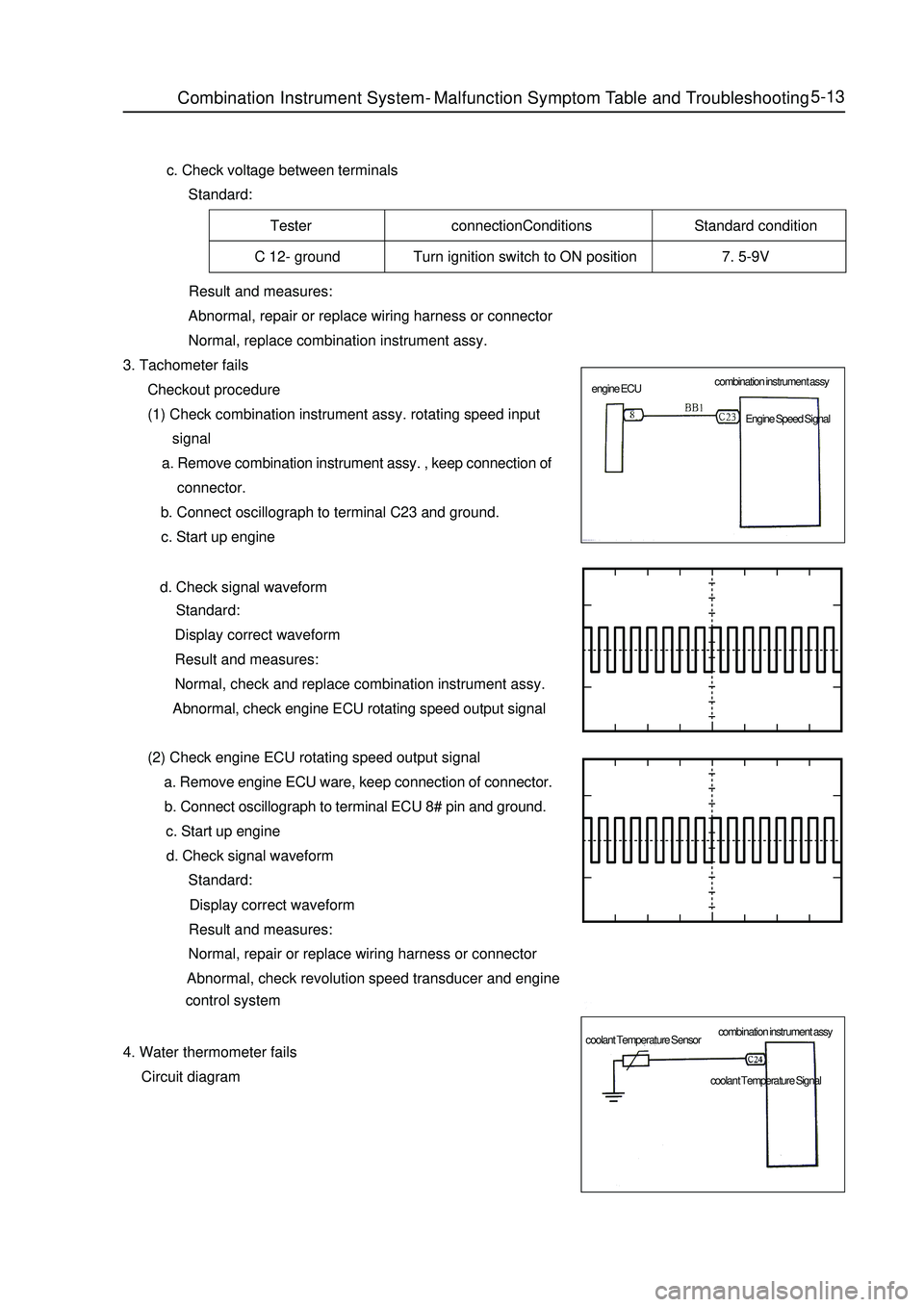
3. Tachometer fails
Checkout procedure
(1) Check combination instrument assy. rotating speed input
signal
a. Remove combination instrument assy. , keep connection of
connector.
b. Connect oscillograph to terminal C23 and ground.
c. Start up engine
d. Check signal waveform
Standard:
Display correct waveform
Result and measures:
Normal, check and replace combination instrument assy.
Abnormal, check engine ECU rotating speed output signal
(2) Check engine ECU rotating speed output signal
a. Remove engine ECU ware, keep connection of connector.
b. Connect oscillograph to terminal ECU 8# pin and ground.
c. Start up engine
d. Check signal waveform
Standard:
Display correct waveform
Result and measures:
Normal, repair or replace wiring harness or connector
Abnormal, check revolution speed transducer and engine
control system
4. Water thermometer fails
Circuit diagramCombination Instrument System -Malfunction Symptom Table and Troubleshooting combination instrument assy
combination instrument assy engine ECU
coolant Temperature SensorEngine Speed Signal
coolant Temperature Signal
Page 201 of 416
Tester connection Conditions Standard state
C(60°C)164.5±5 ohm
C 24- ground 1/2C(90°C)56±3 ohm
H(115°C)28.7±2 ohmConditions Standard state
C(60°C)164.5±5 ohm
1/2C(90°C)56±3 ohm
H(115°C)28.7±2 ohm5-14 (1) Use diagnostic instrument to read engine water temperature value
a. Connect diagnostic instrument to diagnostic interface
b. Turn on ignition switch
c. Read water temperature value displayed on diagnostic instrument
Standard: the same as actual engine cooling water temperature
Result and measures:
Normal, water thermometer does not fail
Abnormal, check combination instrument assy.
(2) Check combination instrument assy.
a. Check resistance
Remove combination instrument assy. , disconnect connector.
Check connection between terminals
Standard:
Result and measures:
Normal, replace combination instrument assy.
Abnormal, check water temperature sensor
b. Check water temperature sensor
Remove water temperature sensor and put it in thermostat.
Adjust temperature of thermostat and measure resistance value of water temperature sensor
Standard:
Result and measures:
Normal, repair or replace wiring harness and connector
Abnormal, replace water temperature sensor
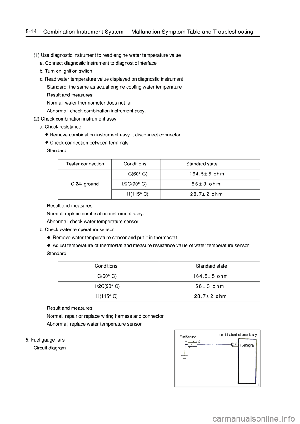
5. Fuel gauge fails
Circuit diagramCombination Instrument System -Malfunction Symptom Table and Troubleshooting combination instrument assy
Fuel Sensor
Fuel Signal
Page 218 of 416

Headlight combination switch position drawingII. Lighting system troubleshooting1. Headlight combination switch assemblyHandle positionTerminal
FU TL TR
Turn
light
switchR
NL
LEL2 FF RF
Foglight
switchOFF
FF
RFE L T N S HEAD
Headlight,
small
light
switchOFF
P
HEL1 HL HU
Light
switchPASS
HL
HUPASSSwitch position Testing terminal Status
OFF EL-TNS OFF
Position light EL-TNS ON
Headlight EL-HEAD ON (1) Check whether headlight light control switch is ON
Check whether terminals are connected when switch is in each position according to the table. If it doest not meet stipulation, replace the switch.Light System -Light System Malfunction Inspection5-31Handle positionTerminalHandle positionTerminalHandle positionTerminalHeadlight combination switch shifting diagram