remove seats GEELY MK 2008 Workshop Manual
[x] Cancel search | Manufacturer: GEELY, Model Year: 2008, Model line: MK, Model: GEELY MK 2008Pages: 416, PDF Size: 25.19 MB
Page 28 of 416

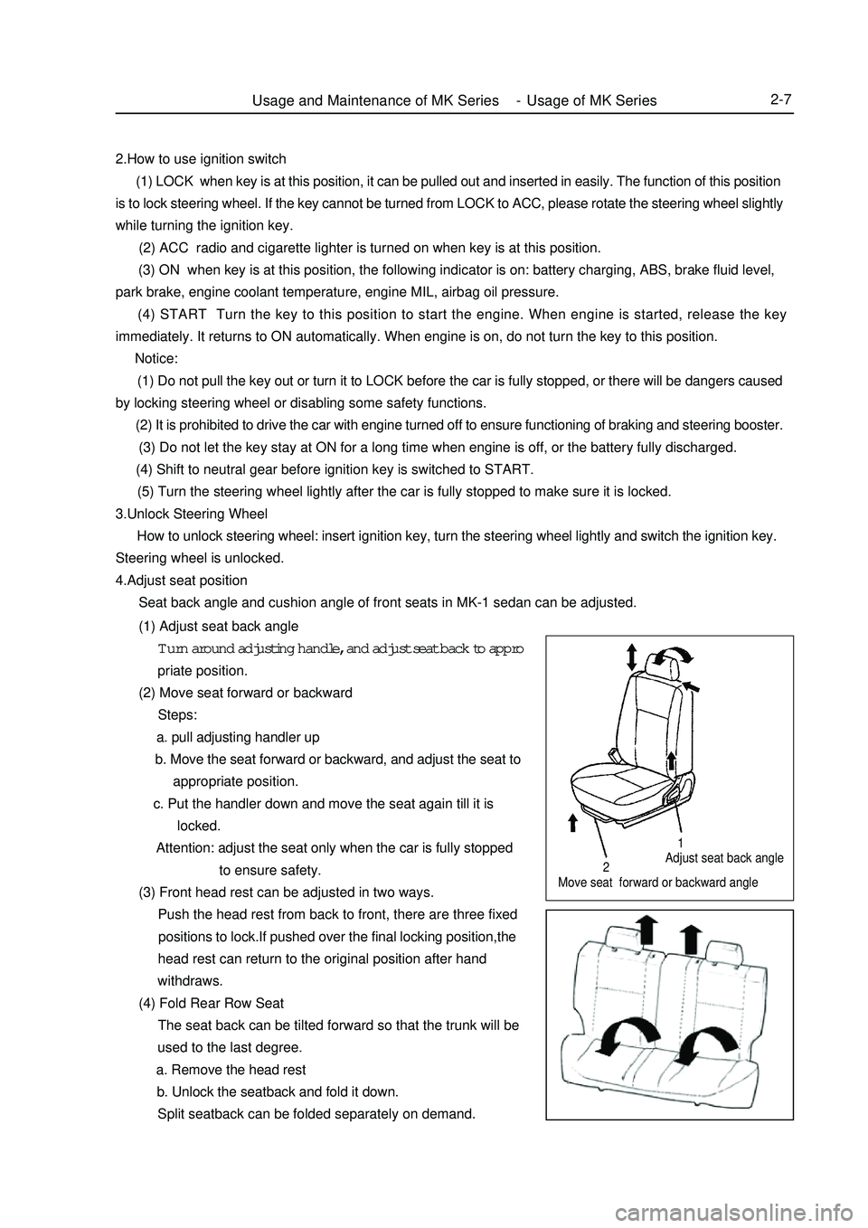
Adjust seat back angle
Move seat forward or backward angleUsage and Maintenance of MK Series - Usage of MK Series2-7212.How to use ignition switch
(1) LOCK when key is at this position, it can be pulled out and inserted in easily. The function of this position
is to lock steering wheel. If the key cannot be turned from LOCK to ACC, please rotate the steering wheel slightly
while turning the ignition key.
(2) ACC radio and cigarette lighter is turned on when key is at this position.
(3) ON when key is at this position, the following indicator is on: battery charging, ABS, brake fluid level,
park brake, engine coolant temperature, engine MIL, airbag oil pressure.
(4) START Turn the key to this position to start the engine. When engine is started, release the key
immediately. It returns to ON automatically. When engine is on, do not turn the key to this position.
Notice:
(1) Do not pull the key out or turn it to LOCK before the car is fully stopped, or there will be dangers caused
by locking steering wheel or disabling some safety functions.
(2) It is prohibited to drive the car with engine turned off to ensure functioning of braking and steering booster.
(3) Do not let the key stay at ON for a long time when engine is off, or the battery fully discharged.
(4) Shift to neutral gear before ignition key is switched to START.
(5) Turn the steering wheel lightly after the car is fully stopped to make sure it is locked.
3.Unlock Steering Wheel
How to unlock steering wheel: insert ignition key, turn the steering wheel lightly and switch the ignition key.
Steering wheel is unlocked.
4.Adjust seat position
Seat back angle and cushion angle of front seats in MK-1 sedan can be adjusted.
(1) Adjust seat back angle
Turn around adjusting handle, and adjust seat back to appro
priate position.
(2) Move seat forward or backward
Steps:
a. pull adjusting handler up
b. Move the seat forward or backward, and adjust the seat to
appropriate position.
c. Put the handler down and move the seat again till it is
locked.
Attention: adjust the seat only when the car is fully stopped
to ensure safety.
(3) Front head rest can be adjusted in two ways.
Push the head rest from back to front, there are three fixed
positions to lock.If pushed over the final locking position,the
head rest can return to the original position after hand
withdraws.
(4) Fold Rear Row Seat
The seat back can be tilted forward so that the trunk will be
used to the last degree.
a. Remove the head rest
b. Unlock the seatback and fold it down.
Split seatback can be folded separately on demand.
Page 115 of 416

Chapter 5 Front Suspension SystemSection 1 Front Suspension SystemDescription on front suspension structureThis model uses strut swing arm independent suspension with stabilizer bar.
The shock absorber upper end is flexibly connected to the body through the shock absorber mounting seat, the
lower end is rigidly connected to the steering knuckle. The coil spring encloses the shock absorber (coil spring
geometrical axial line does not coincide with that of the shock absorber piston rod), and is supported between the
upper and lower spring seats.
Both ends of the stabilizer bar are connected to the shock absorber through the strut bar ball pin and the intermediate
part is supported on the lower front body by the rubber bushing and support frame.
The front cushion sleeves the shock absorber piston rod head to restrict the wheel jump limit position and plays
the role of buffer.
The thrust ball bearing, installed between the spring upper seat and the shock absorber mount, is used for the
relative rotation upon steering of the shock absorber rigidly connected to the steering knuckle to the shock absorber
mount flexibly connected to the body.
"L" type lower swing arm is secured to the lower engine compartment with the press plate through elastic rubber
bushing and hinge, and its outer end is connected to the steering knuckle through the ball stud pin which is attached
to the lower swing arm by 3 high intension bolts. The ball stud pin can be removed and replaced when it is worn.
The ball seat material is saturated polyester containing oil, featured in comparatively high intensity and wearability
and good self-lubrication performance. Proper amount of grease has been added during the assembly and there is
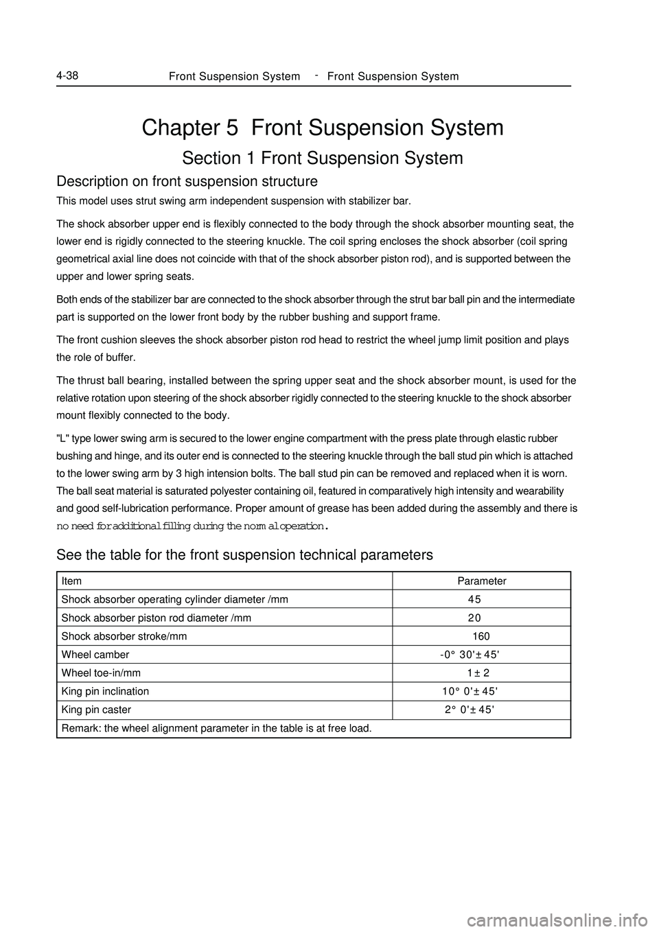
no need for additional filling during the normal operation.See the table for the front suspension technical parametersFront Suspension SystemFront Suspension System4-38Item
Shock absorber operating cylinder diameter /mm
Shock absorber piston rod diameter /mm
Shock absorber stroke/mm
Wheel camber
Wheel toe-in/mm
King pin inclination
King pin caster
Remark: the wheel alignment parameter in the table is at free load.Parameter
45
20
160
-0°30'±45'
1±2
10°0'±45'
2°0'±45' -