steering wheel adjustment GEELY MK 2008 Workshop Manual
[x] Cancel search | Manufacturer: GEELY, Model Year: 2008, Model line: MK, Model: GEELY MK 2008Pages: 416, PDF Size: 25.19 MB
Page 36 of 416

2-15
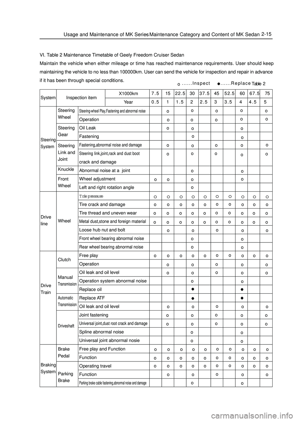
VI. Table 2 Maintenance Timetable of Geely Freedom Cruiser SedanMaintain the vehicle when either mileage or time has reached maintenance requirements. User should keep
maintaining the vehicle to no less than 100000km. User can send the vehicle for inspection and repair in advance
if it has been through special conditions.SystemInspection itemX1000km
Year7.5 15 22.5 30 37.5 45 52.5 60 67.5 75
0.5 1 1.5 2 2.5 3 3.5 4 4.5 5Steering
SystemSteering-wheel Play,Fastening and abnormal noiseOperation
Oil Leak
FasteningFastening,abnormal noise and damage
Steering link,joint,rack and dust bootcrack and damage
Abnormal noise at a joint
Wheel adjustment
Left and right rotation angle
Trie pressure
Tire crack and damage
Tire thread and uneven wearMetal dust,stone and foreign materialLoose hub nut and boltFront wheel bearing abnormal noise
Rear wheel bearing abnormal noiseFree play
Operation
Oil leak and oil level
Operation system abnormal noise
Replace oil
Replace ATF
Oil leak and oil level
Joint fasteningUniversal joint,dust root crack and damageSpline abnormal noise
Universal joint abnormal nosie
Free play and Function
Function
Operating travel
FunctionParking brake cable fastening,abnormal noise and damageo......Inspect ......ReplaceTable 2 Drive
line
Drive
Train
Braking
SystemSteering
Wheel
Steering
Gear
Steering
Link and
Joint
Knuckle
Front
Wheel
Wheel
Clutch
ManualTransmissionAutomaticTransmissionDriveshaftBrake
Pedal
Parking
BrakeUsage and Maintenance of MK Series - Maintenance Category and Content of MK Sedano
o
oo
o o oo o
o o
oo
o o
oo
ooo
o
o oo
o ooo
o o o
o
oo o o o
o o o o
o
oo o o o
o o o o
o
oo o o o
o o o o
o
oo o o o
o o o o
o
oo o o o
o o o o
o
oo o o o
o o o o
o
oo o o o
o o o o
o
oo o o o
o o o o
oo o o
o
o
o o o
o
o
o o o
o
o
o o o
o
o
o o o
o
o
o o o
o
oo o
o o
o o
o o
o o
o oo o o
o
o
Page 116 of 416

Suspected Area
1. Tires (Worn or improperly inflated)
2. Wheel alignment (Incorrect)
3. Steering system joint (Loose or worn)
4. Hub bearing (Worn)
5. Steering gear (Out of adjustment or worn)
6. Suspension parts (Worn or damaged)
1. Vehicle (Overloaded)
2. Spring (stiffness not comply with or damage)
3. Shock absorber (Worn)
1. Tire (Worn or improperly inflated)
2. Steering linkage (Loose or damaged)
3. Stabilizer bar (Bent or broken)
4. Shock absorber (Worn or damaged)
1. Tire (Worn or improperly inflated)
2. Tire (Dynamic balance is not as specified)
3. Shock absorber (Worn or damaged)
4. Wheel alignment (Incorrect)
5. Ball stud pin (Worn or damaged)
6. Hub bearing (Worn or damaged)
7. Steering linkage (Loose or worn)
8. Steering gear (Out of adjustment or worn)
1. Tire (Worn or improperly inflated)
2. Wheel alignment (Incorrect)
3. Shock absorber (Worn or damaged)
4. Suspension parts (Worn or damaged)Symptom Table Use the table below to help you find the cause of the problem. The numbers indicate the priority of the likely
cause of the problem. Check each part in order. If necessary, replace parts.
Symptom
Off track
Body Descent
Sways
Front wheel shimmy
Abnormal tire wearFront Suspension System-Front Suspension System4-39
Page 121 of 416

Camber angle
Left-right wheel deviation
Caster angle
Manual steering
Power steering
Left-right wheel deviation
Kingpin inclination
Manual steering
Power steering
Left-right wheel deviation-0°30' ± 45' (-0.5° ± 0.75°)
45'(0.75°) or smaller
1°46' ± 45' (1.76° ± 0.75°)
45' (0.75°) or smaller
9°54' ± 45' (9.90° ± 0.75°)
45' (0.75°) or lessFront Suspension SystemFront Wheel Alignment4-44Manual steering Power steering
Inside wheel 9-137.2°±2°
Outside wheel32°±2° 32°±2°5. Check the steering angle of wheel
Fully steer the wheel and measure the angle
The angle of wheel:
If the kingpin caster angle and the kingpin inclination be out of spec, check the damage and abrasion of
suspension parts after the correct adjustment of camber angle. If there is deviation with spec for right and left wheel angle, check the rack length of left and right ends.
6. Check the camber, caster and steering axle inclination angle
7. Adjust the camber angle
Notice:
Check the toe-in after adjust the camber angle
(1)Remove the front wheel
(2)Remove the two nuts under the shock absorber
If you need to reuse the bolts and nuts, apply the engine oil on
the nut thread
(3)Clear the mounting surface of the knuckle and shock absorber.Front
Inside
Outside
meter
locator-9-1
Page 212 of 416

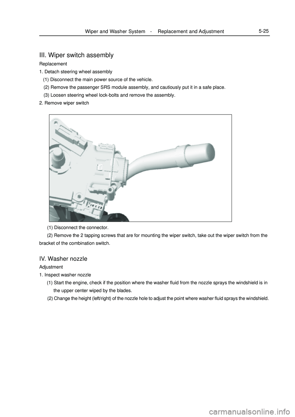
III. Wiper switch assemblyReplacement
1. Detach steering wheel assembly
(1) Disconnect the main power source of the vehicle.
(2) Remove the passenger SRS module assembly, and cautiously put it in a safe place.
(3) Loosen steering wheel lock-bolts and remove the assembly.
2. Remove wiper switch (1) Disconnect the connector.
(2) Remove the 2 tapping screws that are for mounting the wiper switch, take out the wiper switch from the
bracket of the combination switch.IV. Washer nozzleAdjustment
1. Inspect washer nozzle
(1) Start the engine, check if the position where the washer fluid from the nozzle sprays the windshield is in
the upper center wiped by the blades.
(2) Change the height (left/right) of the nozzle hole to adjust the point where washer fluid sprays the windshield.Wiper and Washer System -Replacement and Adjustment5-25