engine GENESIS G80 2019 Quick Reference Guide
[x] Cancel search | Manufacturer: GENESIS, Model Year: 2019, Model line: G80, Model: GENESIS G80 2019Pages: 15, PDF Size: 5.21 MB
Page 1 of 15

Looking For more detailed information? This Quick Reference Guide does not replace your vehicle’sOwner’s Manual. If you require additional information or are unsure of a specific issue, we recommend that you always refer to the vehicle’s Owner’s Manual or contact your authorized retailer of Genesis Branded Products. The information contained in this Quick Reference Guide is correct at the time of printing; however, specifications and equipment can change without notice. No warranty or guarantee is being extended in this Quick Reference Guide, and Genesis Brand reserves the right to change product specifications and equipment at any time without incurring obligations. Some vehicles are shown with optional equipment.
MAINTENANCE
Low tire pressure indicator /
TPMS malfunction indicator
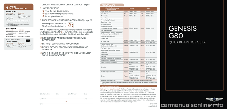
Scheduled Maintenance(Normal Usage)3.8L / 5.0L3.3T
Engine Oil And FilterReplace7,500 or 12 mos.Replace6,000 or 12 mos.
Fuel AdditivesAdd7,500 or 12 mos.Add6,000 or 12 mos.
Tire RotationPerform7,500 or 12 mos.Perform6,000 or 12 mos.
Vacuum Hose
Inspect7,500 or 12 mos.Inspect6,000 or 12 mos.
Air Conditioning Refrigerant
Brake Hoses & Lines
Drive Shafts & Boots
Exhaust Pipe & Muffler
Front Brake Disc/Pads, Calipers
Rear Brake Disc/Pads
Steering Gear Box, Linkage & Boots/ Lower Arm Ball Joint, Upper Arm Ball Joint
Suspension Mounting Bolts
Propeller Shaft
Air Cleaner FilerInspect7,500 or 12 mos.Inspect6,000 or 12 mos.
Replace22,500 or 36 mos.Replace18,000 or 36 mos.
Climate Control Air Filter (For Evaporator And Blower Unit)Replace15,000 or 12 mosInspect12,000 or 12 mos.
Fuel Tank Air Filter
Inspect15,000 or 24 mos.12,000 or 24 mos.
Vapor Hose & Fuel Filler Cap, Fuel tank
Brake Fluid
Parking Brake
Fuel Filter
Fuel Lines, Fuel Hoses And ConnectionsInspect30,000 or 48 mos.Inspect24,000 or 48 mos.Front(AWD)/Rear Differential Oil
Valve Clearance (3.3T and 3.8L)Inspect60,000 or 72 mos.Inspect60,000 or 72 mos.
Drive BeltInspect
First 60,000 or 72 mos.InspectFirst 60,000 or 72 mos.
Subsequent, every 15,000 or 24 mos.InspectSubsequent, every 12,000 or 24 mos.
Spark Plugs (Iridium Coated)Replace105,000Replace42,000
CoolantReplace
First 120,000 or 120 mos.Replace
First 120,000 or 120 mos.
Subsequent, every 30,000 or 24 mos.Subsequent, every 30,000 or 24 mos.
Automatic Transmission FluidNo checks or services required for Normal Usage driving.
*Check the engine oil regularly between recommended oil change. Genesis Branded Vehicle recommend Quaker State oil.
*See Owner’s Manual for details.
☐ TIRE PRESSURE MONITORING SYSTEM (TPMS)- page 20
NOTE: Tire pressure may vary in colder temperatures causing the
low tire pressure indicator to illuminate. Inflate tires according to
the Tire Pressure Label located on the driver’s side door pillar.
☐ HOW TO DEFROST
1 Press the front defrost button.
2 Set to warmest temperature setting.
3 Set to highest fan speed.
☐ DEMONSTRATE AUTOMATIC CLIMATE CONTROL - page 11
NP150-G2019(Rev 06/05/18)Printing 06/08/18
GENESIS
G80
QUICK REFERENCE GUIDE
VOICE
RE COGNITION TIPS
Command ExampleBL UET OOTH®
Dial
Call
7 -1-4- 0-0-0- 8-8-8-8”
“Call John Smith ”
Command ExampleNA VIG ATION
Find Addr ess
2-3-4-5 1s t Stree t,
F oun tain Valle y”
C ommand Example
Loca ted on R earview Mirr or L OC AL SEAR CH
Find
ow e’s ® near me”
“S tarbuck s®”
Impr oving ho w you s tor e your con tacts can op timize your
Blue too th® Voic e R ecognition perf ormance:
• U se full names ins tead o f short or single-s yllable names
(“ John or Dad”)
• Avoid using special char acters/emojis or abbrevia tions
(“Dr .”) when sa ving contacts
Find
Sales Consultant Date Sales Manager Date
Customer Date
Email
@
☐ INTRODUCTION AND LOCATION OF THE SERVICE
DEPARTMENT
☐ SET FIRST SERVICE VALET APPOINTMENT
☐ REVIEW FACTORY RECOMMENDED MAINTENANCE
SCHEDULE
☐ WAS THE CONDITION OF YOUR VEHICLE (AT DELIVERY)
TO YOUR SATISFACTION?
Page 7 of 15

Quick Reference Guide I 0807 I Quick Reference Guide
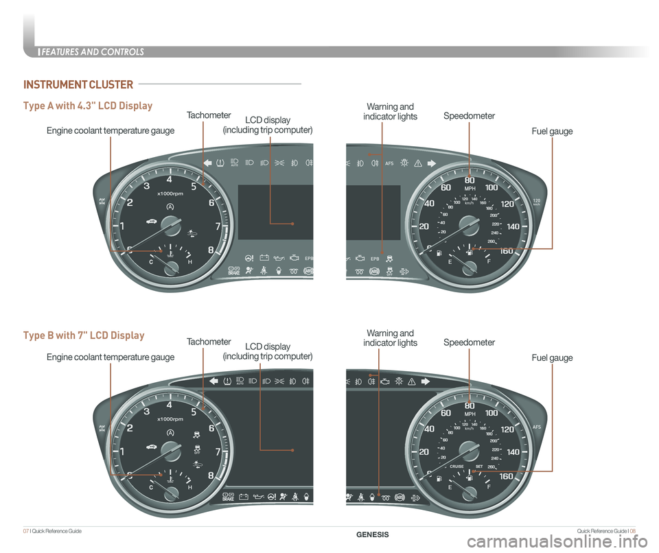
Tachometer
Engine coolant temperature gauge
LCD display
(including trip computer)
Type A with 4.3" LCD Display
Type B with 7" LCD DisplayTachometer
Engine coolant temperature gauge
LCD display
(including trip computer)
Fuel gauge
SpeedometerWarning and
indicator lights
Fuel gauge
SpeedometerWarning and
indicator lights
INSTRUMENT CLUSTER
FEATURES AND CONTROLS
GENESIS
Page 8 of 15

Quick Reference Guide I 1009 I Quick Reference Guide
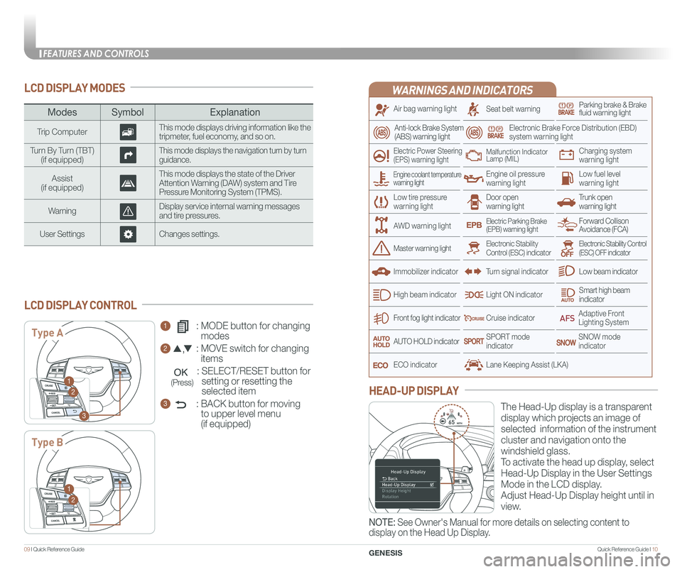
LCD DISPLAY MODES
ModesSymbol Explanation
Trip ComputerThis mode displays driving information like the tripmeter, fuel economy, and so on.
Turn By Turn (TBT)(if equipped)This mode displays the navigation turn by turn guidance.
Assist(if equipped)
This mode displays the state of the Driver Attention Warning (DAW) system and Tire Pressure Monitoring System (TPMS).
WarningDisplay service internal warning messages and tire pressures.
User SettingsChanges settings.
1 : MODE button for changing
modes
2 : MOVE switch for changing
items
: SELECT/RESET button for
setting or resetting the
selected item
3 : BACK button for moving
to upper level menu
(if equipped)
LCD DISPLAY CONTROL
Type A
Type B
1
2
3
1
2
(Press)
WARNINGS AND INDICATORS
Air bag warning light
Electric Power Steering (EPS) warning light
Seat belt warningParking brake & Brake fluid warning light
Electronic Brake Force Distribution (EBD) system warning light
Low tire pressurewarning lightTrunk open warning light
Low fuel level warning light
Front fog light indicator
Low beam indicator
Smart high beam indicator
SNOW modeindicator
Light ON indicator
ECO indicator
SPORT modeindicator
Anti-lock Brake System(ABS) warning light
High beam indicator
Door open warning light
Electronic Stability Control (ESC) indicatorMaster warning light
Forward Collison Avoidance (FCA)Electric Parking Brake(EPB) warning light
Engine oil pressure warning light
Charging system warning light
Immobilizer indicator
Malfunction IndicatorLamp (MIL)
Electronic Stability Control (ESC) OFF indicator
Cruise indicator
Lane Keeping Assist (LKA)
Adaptive Front Lighting System
AUTO HOLD indicator
Turn signal indicator
The Head-Up display is a transparent
display which projects an image of
selected information of the instrument
cluster and navigation onto the
windshield glass.
To activate the head up display, select
Head-Up Display in the User Settings
Mode in the LCD display.
Adjust Head-Up Display height until in
view.
HEAD-UP DISPLAY
Engine coolant temperature warning light
AWD warning light
NOTE: See Owner's Manual for more details on selecting content to
display on the Head Up Display.
FEATURES AND CONTROLS
GENESIS
Page 10 of 15

Quick Reference Guide I 1413 I Quick Reference Guide
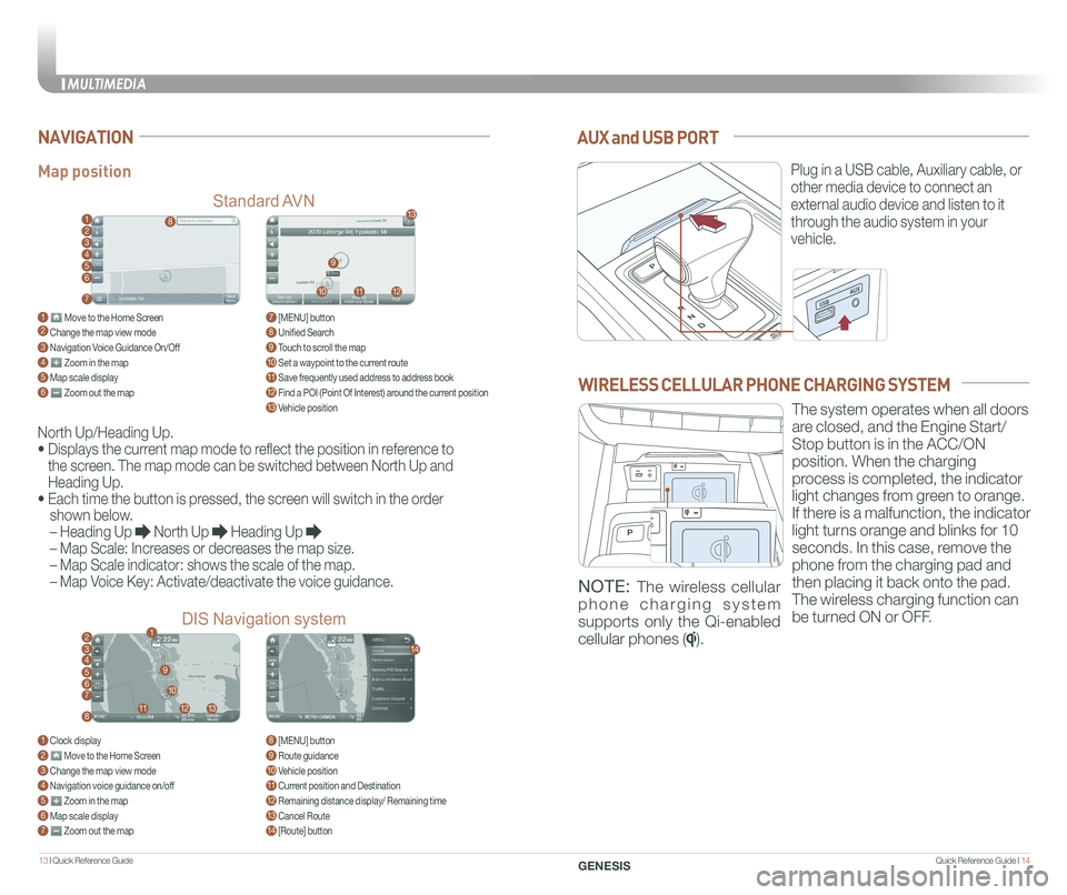
AUX and USB PORT
Plug in a USB cable, Auxiliary cable, or
other media device to connect an
external audio device and listen to it
through the audio system in your
vehicle.
Map position
Standard AVN
DIS Navigation system
NAVIGATION
North Up/Heading Up.
• Displays the current map mode to reflect the position in reference to
the screen. The map mode can be switched between North Up and
Heading Up.
• Each time the button is pressed, the screen will switch in the order
shown below.
– Heading Up North Up Heading Up
– Map Scale: Increases or decreases the map size.
– Map Scale indicator: shows the scale of the map.
– Map Voice Key: Activate/deactivate the voice guidance.
1 Move to the Home Screen2 Change the map view mode3 Navigation Voice Guidance On/Off4 Zoom in the map5 Map scale display6 Zoom out the map
1 Clock display2 Move to the Home Screen3 Change the map view mode4 Navigation voice guidance on/off5 Zoom in the map6 Map scale display7 Zoom out the map
7 [MENU] button 8 Unified Search9 Touch to scroll the map10 Set a waypoint to the current route11 Save frequently used address to address book12 Find a POI (Point Of Interest) around the current position13 Vehicle position
8 [MENU] button9 Route guidance10 Vehicle position11 Current position and Destination12 Remaining distance display/ Remaining time13 Cancel Route14 [Route] button
1
21
34567
81112
9
13
10
14
8
9
101112
13
23456
7
WIRELESS CELLULAR PHONE CHARGING SYSTEM
The system operates when all doors
are closed, and the Engine Start/
Stop button is in the ACC/ON
position. When the charging
process is completed, the indicator
light changes from green to orange.
If there is a malfunction, the indicator
light turns orange and blinks for 10
seconds. In this case, remove the
phone from the charging pad and
then placing it back onto the pad.
The wireless charging function can
be turned ON or OFF.
NOTE: The wireless cellular
phone charging system
supports only the Qi-enabled
cellular phones ().
MULTIMEDIA
GENESIS