display GENESIS G90 2017 Owners Manual
[x] Cancel search | Manufacturer: GENESIS, Model Year: 2017, Model line: G90, Model: GENESIS G90 2017Pages: 524, PDF Size: 19.3 MB
Page 360 of 524

5-99
05
Resetting the System
The last break time is set to 00:00and the driver's attention level is
set to 5 (very attentive) when the
driver resets the Driver Attention
Alert system.
The Driver Attention Alert system resets the last break time to 00:00
and the driver's attention level to 5
in the following situations.
- The engine is turned OFF.
- The driver unfastens the seat beltand then opens the driver's door.
- The engine has been idled con- tinuously over 10 minutes.
The Driver Attention Alert system operates again, when the driver
restarts driving.
System Standby
The Driver Attention Alert system
enters the ready status and displays
the 'Standby' screen in the following
situations.
- The camera sensor keeps failing todetect the lanes.
- Driving speed remains under 40 mph (60 km/h) or over 110 mph
(180 km/h).
OHI056218LOHI056215L
Page 376 of 524
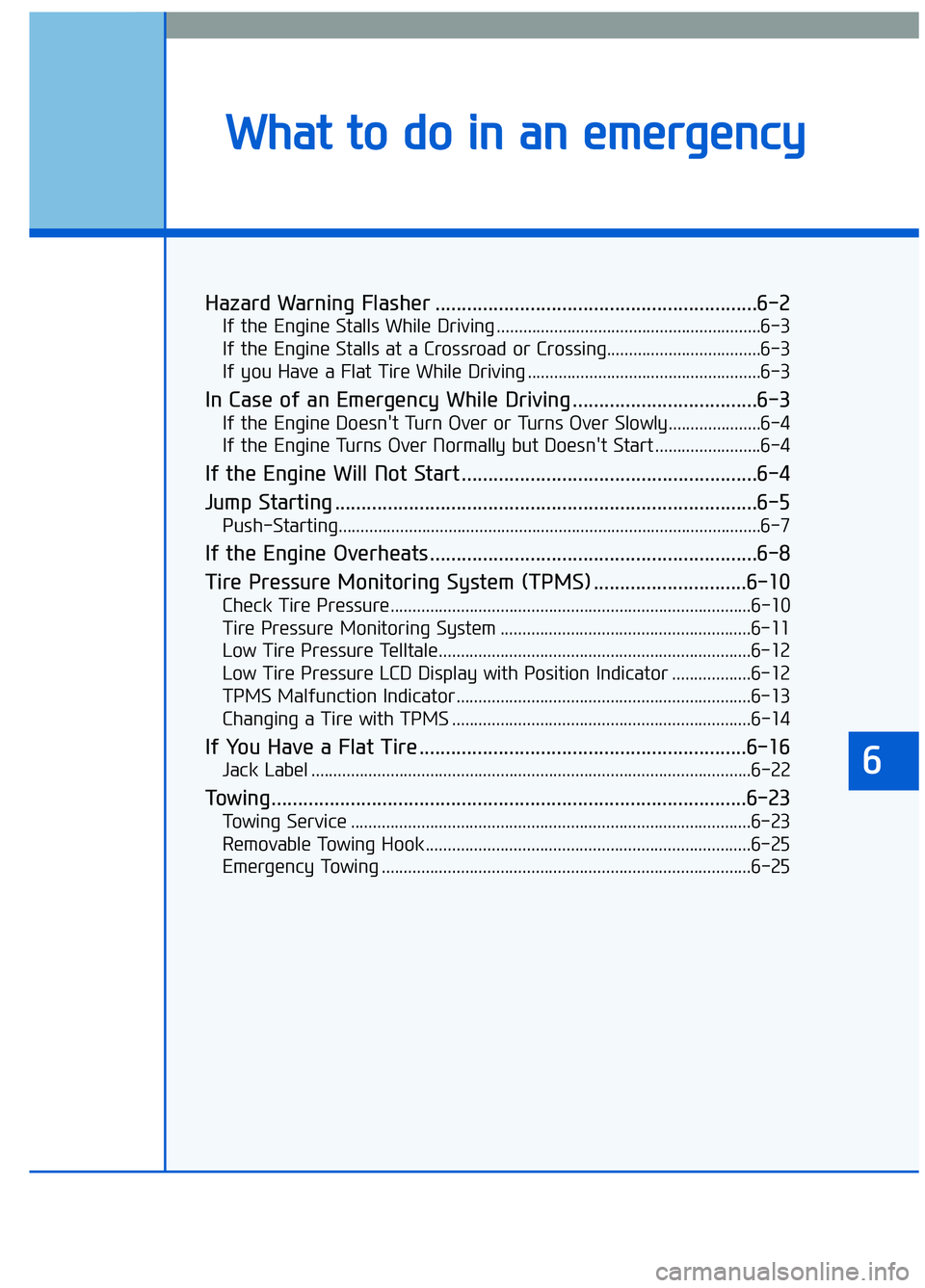
Hazard Warning Flasher .............................................................6-2
If the Engine Stalls While Driving ............................................................6-3
If the Engine Stalls at a Crossroad or Crossing...................................6-3
If you Have a Flat Tire While Driving .....................................................6-3
In Case of an Emergency While Driving ...................................6-3
If the Engine Doesn't Turn Over or Turns Over Slowly.....................6-4
If the Engine Turns Over Normally but Doesn't Start ........................6-4
If the Engine Will Not Start ........................................................6-4
Jump Starting ........................................................................\
........6-5
Push-Starting........................................................................\
........................6-7
If the Engine Overheats ..............................................................6-8
Tire Pressure Monitoring System (TPMS) .............................6-10
Check Tire Pressure........................................................................\
..........6-10
Tire Pressure Monitoring System .........................................................6-11
Low Tire Pressure Telltale.......................................................................6\
-12
Low Tire Pressure LCD Display with Position Indicator ..................6-12
TPMS Malfunction Indicator...................................................................6-13
Changing a Tire with TPMS ....................................................................6-14\
If You Have a Flat Tire ..............................................................6-16
Jack Label ........................................................................\
............................6-22
Towing........................................................................\
..................6-23
Towing Service ........................................................................\
...................6-23
Removable Towing Hook ........................................................................\
..6-25
Emergency Towing ........................................................................\
............6-25
6
W Wh
ha
at
t
t
t o
o
d
d o
o
i
in
n
a
a n
n
e
e m
m e
er
rg
g e
en
n c
cy
y
Page 385 of 524
6-10
What to do in an emergency
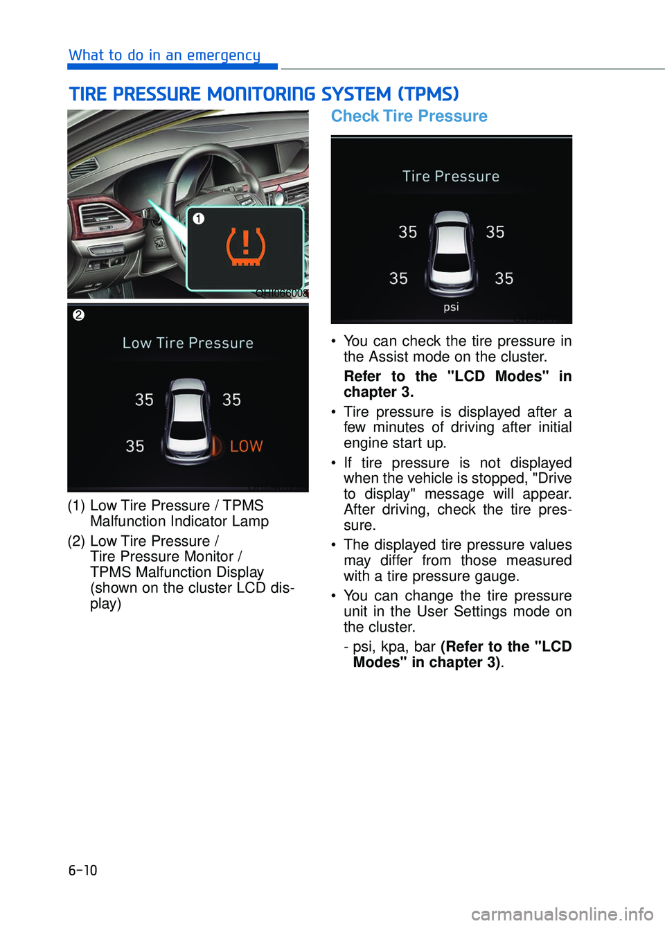
(1) Low Tire Pressure / TPMS Malfunction Indicator Lamp
(2) Low Tire Pressure / Tire Pressure Monitor /
TPMS Malfunction Display
(shown on the cluster LCD dis-
play)
Check Tire Pressure
You can check the tire pressure inthe Assist mode on the cluster.
Refer to the "LCD Modes" in
chapter 3.
Tire pressure is displayed after a few minutes of driving after initial
engine start up.
If tire pressure is not displayed when the vehicle is stopped, "Drive
to display" message will appear.
After driving, check the tire pres-
sure.
The displayed tire pressure values may differ from those measured
with a tire pressure gauge.
You can change the tire pressure unit in the User Settings mode on
the cluster.
- psi, kpa, bar (Refer to the "LCDModes" in chapter 3) .
T TI
IR
R E
E
P
P R
R E
ES
SS
SU
U R
RE
E
M
M O
ON
NI
IT
T O
O R
RI
IN
N G
G
S
S Y
Y S
ST
T E
EM
M
(
( T
T P
P M
M S
S)
)
OHI066008
OHI046129N
OHI046160L
Page 387 of 524
6-12
What to do in an emergency
Information
If any of the below happens, have the
system checked by an authorized
Dealer of Genesis Brand Products.
1. The Low Tire Pressure Telltale/TPMS Malfunction Indicator does
not illuminate for 3 seconds when
the Engine Start/Stop button is
turned to the ON position or engine
is running.
2. The TPMS Malfunction Indicator remains illuminated after blinking
for approximately 1 minute.
3. The Low Tire Pressure Position Telltale remains illuminated.
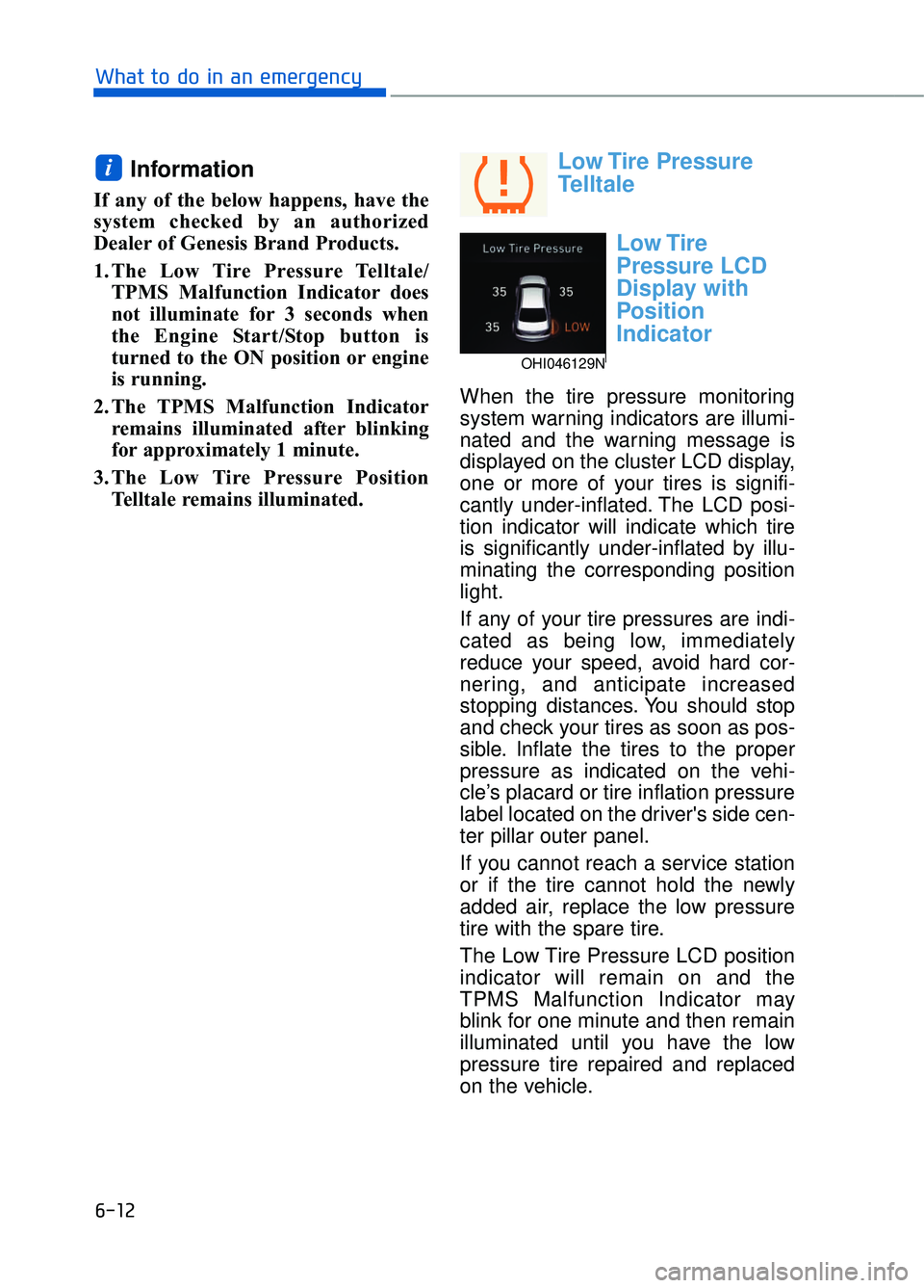
Low Tire Pressure
Telltale
Low Tire
Pressure LCD
Display with
Position
Indicator
When the tire pressure monitoring
system warning indicators are illumi-
nated and the warning message is
displayed on the cluster LCD display,
one or more of your tires is signifi-
cantly under-inflated. The LCD posi-
tion indicator will indicate which tire
is significantly under-inflated by illu-
minating the corresponding position
light.
If any of your tire pressures are indi-
cated as being low, immediately
reduce your speed, avoid hard cor-
nering, and anticipate increased
stopping distances. You should stop
and check your tires as soon as pos-
sible. Inflate the tires to the proper
pressure as indicated on the vehi-
cle’s placard or tire inflation pressure
label located on the driver's side cen-
ter pillar outer panel.
If you cannot reach a service station
or if the tire cannot hold the newly
added air, replace the low pressure
tire with the spare tire.
The Low Tire Pressure LCD position
indicator will remain on and the
TPMS Malfunction Indicator may
blink for one minute and then remain
illuminated until you have the low
pressure tire repaired and replaced
on the vehicle.
i
OHI046129N
Page 388 of 524
6-13
06
Information
The spare tire is not equipped with a
tire pressure sensor.
In winter or cold weather, the Low
Tire Pressure Telltale may be illu-
minated if the tire pressure was
adjusted to the recommended tire
inflation pressure in warm weather.
It does not mean your TPMS is mal-
functioning because the decreased
temperature leads to a proportion-
al lowering of tire pressure.
When you drive your vehicle from
a warm area to a cold area or from
a cold area to a warm area, or the
outside temperature is greatly
higher or lower, you should check
the tire inflation pressure and
adjust the tires to the recommend-
ed tire inflation pressure.
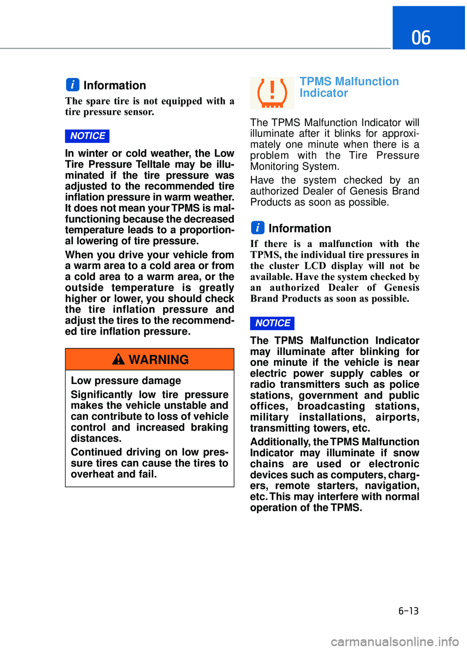
TPMS Malfunction
Indicator
The TPMS Malfunction Indicator will
illuminate after it blinks for approxi-
mately one minute when there is a
problem with the Tire Pressure
Monitoring System.
Have the system checked by an
authorized Dealer of Genesis Brand
Products as soon as possible.
Information
If there is a malfunction with the
TPMS, the individual tire pressures in
the cluster LCD display will not be
available. Have the system checked by
an authorized Dealer of Genesis
Brand Products as soon as possible.
The TPMS Malfunction Indicator
may illuminate after blinking for
one minute if the vehicle is near
electric power supply cables or
radio transmitters such as police
stations, government and public
offices, broadcasting stations,
military installations, airports,
transmitting towers, etc.
Additionally, the TPMS Malfunction
Indicator may illuminate if snow
chains are used or electronic
devices such as computers, charg-
ers, remote starters, navigation,
etc. This may interfere with normal
operation of the TPMS.
NOTICE
i
NOTICE
i
Low pressure damage
Significantly low tire pressure
makes the vehicle unstable and
can contribute to loss of vehicle
control and increased braking
distances.
Continued driving on low pres-
sure tires can cause the tires to
overheat and fail.
WARNING
Page 452 of 524

7-50
Maintenance
Wheel size designation
Wheels are also marked with impor-
tant information that you need if you
ever have to replace one. The follow-
ing explains what the letters and
numbers in the wheel size designa-
tion mean.
Example wheel size designation:
8.5J X 19
8.5 - Rim width in inches.
J - Rim contour designation.
19 - Rim diameter in inches.
Tire speed ratings
The chart below lists many of the dif-
ferent speed ratings currently being
used for passenger car tires. The
speed rating is part of the tire size
designation on the sidewall of the
tire. This symbol corresponds to that
tire’s designed maximum safe oper-
ating speed.
3. Checking tire life (TIN : TireIdentification Number)
Any tires that are over six years old,
based on the manufacturing date,
(including the spare tire) should be
replaced by new ones. You can find
the manufacturing date on the tire
sidewall (possibly on the inside of the
wheel), displaying the DOT Code.
The DOT Code is a series of num-
bers on a tire consisting of numbers
and English letters. The manufactur-
ing date is designated by the last four
digits (characters) of the DOT code.
DOT : XXXX XXXX OOOO
The front part of the DOT means a
plant code number, tire size and
tread pattern and the last four num-
bers indicate week and year manu-
factured.
For example:
DOT XXXX XXXX 2216 represents
that the tire was produced in the 22th
week of 2016.
Speed
Rating
Symbol Maximum Speed
S 112 mph (180 km/h) T 118 mph (190 km/h)
H 130 mph (210 km/h) V 149 mph (240 km/h)
W 168 mph (270 km/h)
Y186 mph (300 km/h)
Page 467 of 524

7-65
07
Instrument panel fuse panel
Fuse name Fuse rating Circuit protected
MODULE5 10AStop Lamp Switch, Driver/Passenger Door Module
MODULE7 10A
Electro Chromic Mirror, A/V & Navigation Head Unit, AMP,
A/C Control Module, Front A/C Controller, Air Quality
Sensor, Rear Seat Warmer Control Module LH/RH Head
Lamp LH/RH Driver/Passenger CCS Module
Rear CCS Module LH/RH, Driver/Passenger IMS Control
Module, Rear IMS Control Module LH/RH, Rear Seat
Console Switch
IBU3 10AIBU Control Module
E-SHIFTER2 10AElectronic ATM Shift Lever
MEMORY1 10A
Security Indicator, A/C Control Module, Front A/C Controller,
Instrument Cluster, Driver/Passenger IMS Control Module,
Rear IMS Control Module LH/RH, Head-Up Display, Analog
Clock
Driver/Passenger Seat Control Switch, Power Trunk Module,
Rear Seat Control Switch LH/RHM Driver/Passenger Smart
Key, Outside Handle Rear Smart Key Outside Handle
LH/RH
RR LH2P/SEAT25ARear IMS Control Module LH
DRIVER
P/SEAT225ADriver IMS Control Module
P/WINDOW RH30APassenger Power Window Module
Rear Power Window Module RH
MODULE 610A
Crash Pad Switch, Blind Spot Detection Radar LH/RH ECS
Unit, Electric Parking Brake Module, Lane Keeping Assist
Module, Front Console Switch, Steering Tilt & Telescopic
Module
MODULE 10 10ACooling Fan Controller (BLDC), Rear Seat Console Switch,
Around View Unit, Parking Guide Unit
MODULE3 10AGATEWAY (B+ (MCU)), Data Link Connector, Hazard
Switch
SUNROOF 25ASunroof Motor
PASSENGER P/SEAT2 25APassenger IMS Control Module
Page 468 of 524
7-66
Maintenance
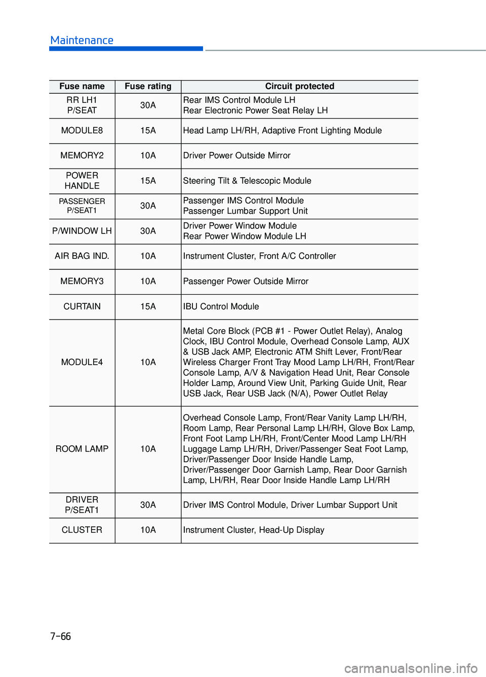
Fuse name Fuse rating Circuit protected
RR LH1P/SEAT 30ARear IMS Control Module LH
Rear Electronic Power Seat Relay LH
MODULE8 15AHead Lamp LH/RH, Adaptive Front Lighting Module
MEMORY2 10ADriver Power Outside Mirror
POWER
HANDLE 15ASteering Tilt & Telescopic Module
PASSENGER P/SEAT1 30APassenger IMS Control Module
Passenger Lumbar Support Unit
P/WINDOW LH30ADriver Power Window Module
Rear Power Window Module LH
AIR BAG IND.10AInstrument Cluster, Front A/C Controller
MEMORY3 10APassenger Power Outside Mirror
CURTAIN 15AIBU Control Module
MODULE4 10A
Metal Core Block (PCB #1 - Power Outlet Relay), Analog
Clock, IBU Control Module, Overhead Console Lamp, AUX
& USB Jack AMP, Electronic ATM Shift Lever, Front/Rear
Wireless Charger Front Tray Mood Lamp LH/RH, Front/Rear
Console Lamp, A/V & Navigation Head Unit, Rear Console
Holder Lamp, Around View Unit, Parking Guide Unit, Rear
USB Jack, Rear USB Jack (N/A), Power Outlet Relay
ROOM LAMP 10A
Overhead Console Lamp, Front/Rear Vanity Lamp LH/RH,
Room Lamp, Rear Personal Lamp LH/RH, Glove Box Lamp,
Front Foot Lamp LH/RH, Front/Center Mood Lamp LH/RH
Luggage Lamp LH/RH, Driver/Passenger Seat Foot Lamp,
Driver/Passenger Door Inside Handle Lamp,
Driver/Passenger Door Garnish Lamp, Rear Door Garnish
Lamp, LH/RH, Rear Door Inside Handle Lamp LH/RH
DRIVER
P/SEAT1 30ADriver IMS Control Module, Driver Lumbar Support Unit
CLUSTER 10AInstrument Cluster, Head-Up Display
Page 507 of 524
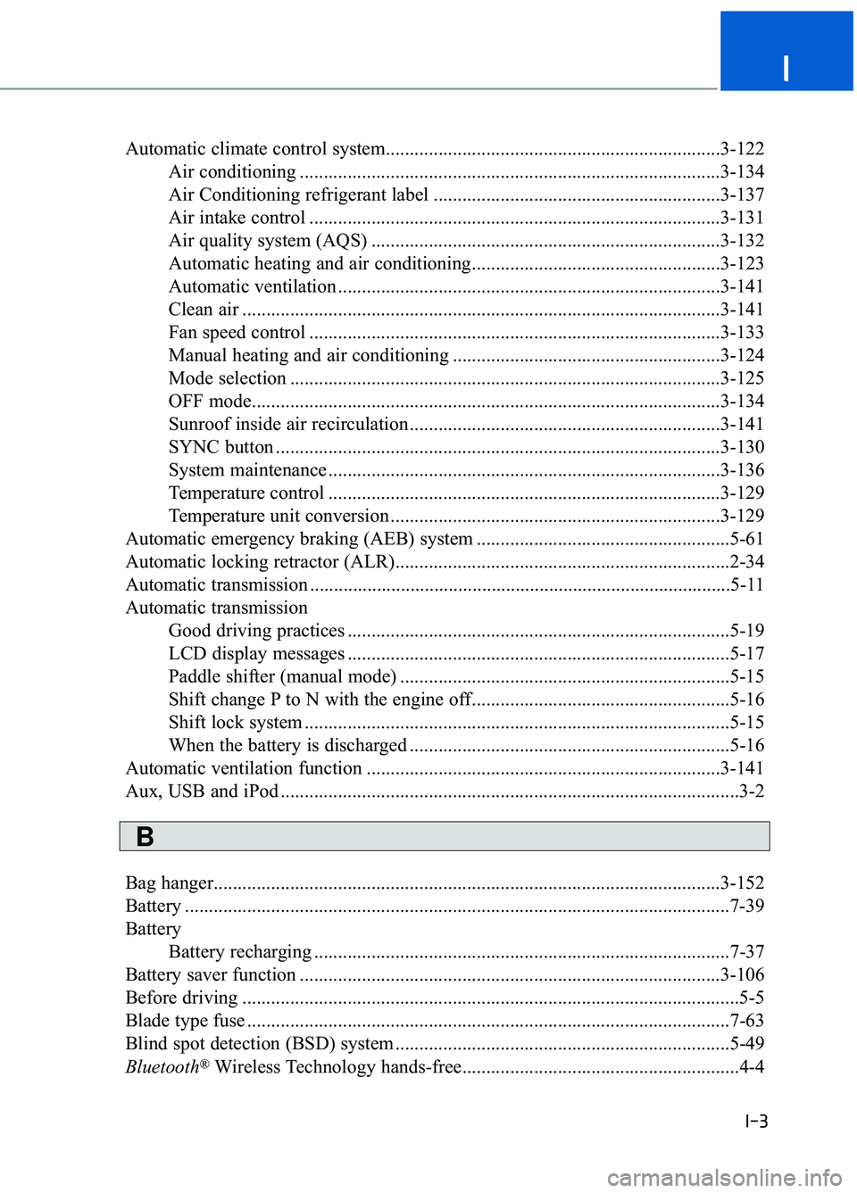
Automatic climate control system......................................................................3-\
122Air conditioning ........................................................................\
................3-134
Air Conditioning refrigerant label ............................................................3-137
Air intake control ........................................................................\
..............3-131
Air quality system (AQS) ........................................................................\
.3-132
Automatic heating and air conditioning....................................................3-123
Automatic ventilation ........................................................................\
........3-141
Clean air ........................................................................\
............................3-141
Fan speed control ........................................................................\
..............3-133
Manual heating and air conditioning ........................................................3-124
Mode selection ........................................................................\
..................3-125
OFF mode........................................................................\
..........................3-134
Sunroof inside air recirculation .................................................................3-141
SYNC button ........................................................................\
.....................3-130
System maintenance ........................................................................\
..........3-136
Temperature control ........................................................................\
..........3-129
Temperature unit conversion .....................................................................3-1\
29
Automatic emergency braking (AEB) system .....................................................5-61
Automatic locking retractor (ALR)......................................................................2-\
34
Automatic transmission ........................................................................\
................5-11
Automatic transmission Good driving practices ........................................................................\
........5-19
LCD display messages ........................................................................\
........5-17
Paddle shifter (manual mode) .....................................................................5-1\
5
Shift change P to N with the engine off......................................................5-16
Shift lock system ........................................................................\
.................5-15
When the battery is discharged ...................................................................5-16
Automatic ventilation function ........................................................................\
..3-141
Aux, USB and iPod ........................................................................\
........................3-2
Bag hanger........................................................................\
..................................3-152
Battery ........................................................................\
..........................................7-39
Battery Battery recharging ........................................................................\
...............7-37
Battery saver function ........................................................................\
................3-106
Before driving ........................................................................\
................................5-5
Blade type fuse ........................................................................\
.............................7-63
Blind spot detection (BSD) system ......................................................................5-\
49
Bluetooth
®Wireless Technology hands-free..........................................................4-4
I-3
I
B
Page 509 of 524

Changing a Tire with TPMS ........................................................................\
........6-14
Checking tire inflation pressure ........................................................................\
...7-45
Child restraint system (CRS) ........................................................................\
.......2-45Booster seats........................................................................\
........................2-48
Children always in the rear ........................................................................\
.2-45
Forward-facing child restraint system ........................................................2-48
Installing a child restraint system (CRS) ....................................................2-48
Lower Anchors and tether for children .......................................................2-49
Rearward-facing child restraint system..................................\
.....................2-47
Securing a child restraint system seat with "Tether Anchor" system .........3-52
Securing a child restraint system with a lap/shoulder belt .........................3-53
Securing a child restraint with the the LATCH anchors system.................2-51
Selecting a child restraint system (CRS) ....................................................2-46
Child-protector rear door lock........................................................................\
......3-13
Clean air ........................................................................\
.....................................3-141
Climate control air filter........................................................................\
...............7-36
Clock ........................................................................\
..........................................3-151
Clothes hanger ........................................................................\
............................3-151
Combined instrument, see instrument cluster ......................................................3-60
Compact spare tire replacement ........................................................................\
...7-48
Consumer information........................................................................\
..................8-10
Coolant ........................................................................\
.........................................7-30
Cooling fluid, see engine coolant........................................................................\
.7-30
Crankcase emission control system .....................................................................7-8\
8
Cruise control system ........................................................................\
...................5-80
Cup holder ........................................................................\
..................................3-147
Curtain air bags ........................................................................\
............................2-62
Dashboard illumination, see instrument panel illumination ................................3-61
Dashboard, see instrument cluster .......................................................................3\
-60
Daytime running light (DRL) ........................................................................\
....3-107
Defogging (Windshield) ........................................................................\
.............3-138
Defroster ........................................................................\
.....................................3-121 Rear window defroster ........................................................................\
......3-121
Side view mirror defroster ........................................................................\
3-121
Defrosting (Windshield) ........................................................................\
.............3-138
Dimensions ........................................................................\
.....................................8-2
DIS navigation system ........................................................................\
...................4-4
Display illumination, see instrument panel illumination .....................................3-61
I-5
I
D