maintenance GENESIS G90 2017 Workshop Manual
[x] Cancel search | Manufacturer: GENESIS, Model Year: 2017, Model line: G90, Model: GENESIS G90 2017Pages: 524, PDF Size: 19.3 MB
Page 450 of 524

7-48
Maintenance
Compact spare tire replacement
A compact spare tire has a shorter
tread life than a regular size tire.
Replace it when you can see the
tread wear indicator bars on the tire.
The replacement compact spare tire
should be the same size and design
tire as the one provided with your
new vehicle and should be mounted
on the same compact spare tire
wheel. The compact spare tire is not
designed to be mounted on a regular
size wheel, and the compact spare
tire wheel is not designed for mount-
ing a regular size tire.
Wheel Replacement
When replacing the metal wheels for
any reason, make sure the new
wheels are equivalent to the original
factory units in diameter, rim width
and offset.
Information
A wheel in the different size may
adversely affect the wheel bearing,
braking, stopping, handling, ground
clearance, body-to-tire clearance,
snow-chain clearance, speedometer,
odometer, headlamp angle and
bumper height.
i
The original tire should be
repaired or replaced as soon as
possible to avoid failure of the
spare and loss of vehicle con-
trol resulting in an accident. The
compact spare tire is for emer-
gency use only. Do not operate
your vehicle over 50 mph (80
km/h) when using the compact
spare tire.
WARNING
Page 451 of 524

7-49
07
Tire Traction
Tire traction can be reduced if you
drive on worn tires, tires that are
improperly inflated or on slippery
road surfaces. Tires should be
replaced when tread wear indicators
appear. To reduce the possibility of
losing control, slow down whenever
there is rain, snow or ice on the road.
Tire Maintenance
In addition to proper inflation, correct
wheel alignment helps to decrease
tire wear. If you find a tire is worn
unevenly, have your dealer check the
wheel alignment.
When you have new tires installed,
make sure they are balanced. This
will increase vehicle ride comfort and
tire life. Additionally, a tire should
always be rebalanced if it is removed
from the wheel.
Tire Sidewall Labeling
This information identifies and
describes the fundamental charac-
teristics of the tire and also provides
the tire identification number (TIN)
for safety standard certification. The
TIN can be used to identify the tire in
case of a recall.
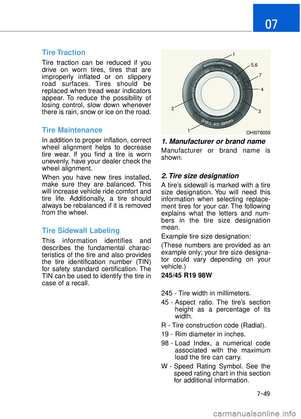
1. Manufacturer or brand name
Manufacturer or brand name is
shown.
2. Tire size designation
A tire’s sidewall is marked with a tire
size designation. You will need this
information when selecting replace-
ment tires for your car. The following
explains what the letters and num-
bers in the tire size designation
mean.
Example tire size designation:
(These numbers are provided as an
example only; your tire size designa-
tor could vary depending on your
vehicle.)
245/45 R19 98W
245 - Tire width in millimeters.
45 - Aspect ratio. The tire’s sectionheight as a percentage of its
width.
R - Tire construction code (Radial).
19 - Rim diameter in inches.
98 - Load Index, a numerical code associated with the maximum
load the tire can carry.
W - Speed Rating Symbol. See the speed rating chart in this section
for additional information.
OHI076059
1
1
2
34
5,6
7
Page 452 of 524

7-50
Maintenance
Wheel size designation
Wheels are also marked with impor-
tant information that you need if you
ever have to replace one. The follow-
ing explains what the letters and
numbers in the wheel size designa-
tion mean.
Example wheel size designation:
8.5J X 19
8.5 - Rim width in inches.
J - Rim contour designation.
19 - Rim diameter in inches.
Tire speed ratings
The chart below lists many of the dif-
ferent speed ratings currently being
used for passenger car tires. The
speed rating is part of the tire size
designation on the sidewall of the
tire. This symbol corresponds to that
tire’s designed maximum safe oper-
ating speed.
3. Checking tire life (TIN : TireIdentification Number)
Any tires that are over six years old,
based on the manufacturing date,
(including the spare tire) should be
replaced by new ones. You can find
the manufacturing date on the tire
sidewall (possibly on the inside of the
wheel), displaying the DOT Code.
The DOT Code is a series of num-
bers on a tire consisting of numbers
and English letters. The manufactur-
ing date is designated by the last four
digits (characters) of the DOT code.
DOT : XXXX XXXX OOOO
The front part of the DOT means a
plant code number, tire size and
tread pattern and the last four num-
bers indicate week and year manu-
factured.
For example:
DOT XXXX XXXX 2216 represents
that the tire was produced in the 22th
week of 2016.
Speed
Rating
Symbol Maximum Speed
S 112 mph (180 km/h) T 118 mph (190 km/h)
H 130 mph (210 km/h) V 149 mph (240 km/h)
W 168 mph (270 km/h)
Y186 mph (300 km/h)
Page 454 of 524

7-52
Maintenance
Traction - AA, A, B & C
The traction grades, from highest to
lowest, are AA, A, B and C. Those
grades represent the tire's ability to
stop on wet pavement as measured
under controlled conditions on spec-
ified government test surfaces of
asphalt and concrete. A tire marked
C may have poor traction perform-
ance.
Temperature - A, B & C
The temperature grades are A (the
highest), B and C representing the
tire’s resistance to the generation of
heat and its ability to dissipate heat
when tested under controlled condi-
tions on a specified indoor laboratory
test wheel.
Sustained high temperature can
cause the material of the tire to
degenerate and reduce tire life, and
excessive temperature can lead to
sudden tire failure. Grade C
responds to a level of performance
which all passenger car tires must
meet under the Federal Motor
Vehicle Safety Standard No. 109.
Grades B and A represent higher
levels of performance on the labora-
tory test wheel than the minimum
required by law.
The traction grade assigned to
this tire is based on straight-
ahead braking traction tests,
and does not include accelera-
tion, cornering, hydroplaning,
or peak traction characteristics.
WARNING
The temperature grade for this
tire is established for a tire that
is properly inflated and not
overloaded. Excessive speed,
under-inflation, over-inflation,
or excessive loading, either
separately or in combination,
can cause heat build-up and
possible sudden tire failure.
This may cause loss of vehicle
control resulting in an accident.
WARNING
Page 456 of 524

7-54
Maintenance
Intended Outboard Sidewall
The side of an asymmetrical tire, that
must always face outward when
mounted on a vehicle.
Kilopascal (kPa)
The metric unit for air pressure.
Light truck(LT) tire
A tire designated by its manufacturer
as primarily intended for use on light-
weight trucks or multipurpose pas-
senger vehicles.
Load ratings
The maximum load that a tire is rated
to carry for a given inflation pressure.
Load Index
An assigned number ranging from 1
to 279 that corresponds to the load
carrying capacity of a tire.
Maximum Inflation Pressure
The maximum air pressure to which
a cold tire may be inflated. The max-
imum air pressure is molded onto the
sidewall.
Maximum Load Rating
The load rating for a tire at the maxi-
mum permissible inflation pressure
for that tire.
Maximum Loaded VehicleWeight
The sum of curb weight; accessory
weight; vehicle capacity weight; and
production options weight.
Normal Occupant Weight
The number of occupants a vehicle
is designed to seat multiplied by 150
pounds (68 kg).
Occupant Distribution
Designated seating positions.
Outward Facing Sidewall
An asymmetrical tire has a particular
side that faces outward when mount-
ed on a vehicle. The outward facing
sidewall bears white lettering or
bears manufacturer, brand, and/or
model name molding that is higher or
deeper than the same moldings on
the inner facing sidewall.
Passenger (P-Metric) tire
A tire used on passenger cars and
some light duty trucks and multipur-
pose vehicles.
Ply
A layer of rubber-coated parallel
cords.
Page 458 of 524

7-56
Maintenance
Vehicle Capacity Weight
The number of designated seating
positions multiplied by 150 lbs. (68
kg) plus the rated cargo and luggage
load.
Vehicle Maximum Load on theTire
Load on an individual tire due to curb
and accessory weight plus maximum
occupant and cargo weight.
Vehicle Normal Load on the Tire
Load on an individual tire that is
determined by distributing to each
axle its share of the curb weight,
accessory weight, and normal occu-
pant weight and dividing by 2.
Vehicle Placard
A label permanently attached to a
vehicle showing the original equip-
ment tire size and recommended
inflation pressure.
All Season Tires
Genesis Brand specifies all season
tires on some models to provide
good performance for use all year
round, including snowy and icy road
conditions. All season tires are iden-
tified by ALL SEASON and/or M+S
(Mud and Snow) on the tire sidewall.
Snow tires have better snow traction
than all season tires and may be
more appropriate in some areas.
Summer Tires
Genesis Brand specifies summer
tires on some models to provide
superior performance on dry roads.
Summer tire performance is sub-
stantially reduced in snow and ice.
Summer tires do not have the tire
traction rating M+S (Mud and Snow)
on the tire side wall. If you plan to
operate your vehicle in snowy or icy
conditions, Genesis Brand recom-
mends the use of snow tires or all
season tires on all four wheels.
Snow Tires
If you equip your car with snow tires,
they should be the same size and
have the same load capacity as the
original tires. Snow tires should be
installed on all four wheels; other-
wise, poor handling may result. Snow
tires should carry 4 psi (28 kPa)
more air pressure than the pressure
recommended for the standard tires
on the tire label on the driver’s side of
the center pillar, or up to the maxi-
mum pressure shown on the tire
sidewall, whichever is less. Do not
drive faster than 75 mph (120 km/h)
when your vehicle is equipped with
snow tires.
Page 460 of 524

7-58
Maintenance
It is not easy to recognize tire damage with your own eyes. But
if there is the slightest hint of
tire damage, have the tire
checked or replaced because
the tire damage may cause air
leakage from the tire.
If the tire is damaged by driving on a rough road, off road, pot-
hole, manhole, or curb stone, it
will not be covered by the war-
ranty.
NOTICE
Page 462 of 524

7-60
Maintenance
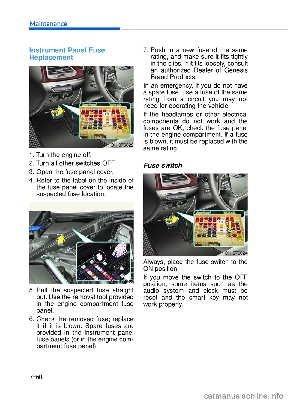
Instrument Panel Fuse
Replacement
1. Turn the engine off.
2. Turn all other switches OFF.
3. Open the fuse panel cover.
4. Refer to the label on the inside ofthe fuse panel cover to locate the
suspected fuse location.
5. Pull the suspected fuse straight out. Use the removal tool provided
in the engine compartment fuse
panel.
6. Check the removed fuse; replace it if it is blown. Spare fuses are
provided in the instrument panel
fuse panels (or in the engine com-
partment fuse panel). 7. Push in a new fuse of the same
rating, and make sure it fits tightly
in the clips. If it fits loosely, consult
an authorized Dealer of Genesis
Brand Products.
In an emergency, if you do not have
a spare fuse, use a fuse of the same
rating from a circuit you may not
need for operating the vehicle.
If the headlamps or other electrical
components do not work and the
fuses are OK, check the fuse panel
in the engine compartment. If a fuse
is blown, it must be replaced with the
same rating.
Fuse switch
Always, place the fuse switch to the
ON position.
If you move the switch to the OFF
position, some items such as the
audio system and clock must be
reset and the smart key may not
work properly.
OHI076022
OHI076023
OHI076024
Page 464 of 524

7-62
MaintenanceAfter checking the fuse box in the
engine compartment securely
close the fuse box cover inside
the engine compartment, until it
clicks.
If the fuse box is not closed prop-
erly, water may leak in side, possi-
bly causing a malfunction with the
electrical system.
Main fuse
If the main fuse is blown, it must be
removed as follows:
1. Turn off the engine.
2. Disconnect the negative battery cable.
3. Remove the fuse panel cover by pressing the tab and pulling it up.
4. Remove the nuts shown in the pic- ture above.
5. Replace the fuse with a new one of the same rating.
6. Reinstall in the reverse order of removal.
Information
If the main fuse is blown, consult an
authorized Dealer of Genesis Brand
Products.
Multi fuse
If the multi fuse is blown, it must be
removed as follows:
1. Turn off the engine.
2. Disconnect the negative batterycable.
3. Remove the fuse panel cover by pressing the tab and pulling it up.
4. Remove the nuts shown in the pic- ture above.
5. Replace the fuse with a new one of the same rating.
6. Reinstall in the reverse order of removal.
Information
If the multi fuse is blown, consult an
authorized Dealer of Genesis Brand
Products.
i
iNOTICE
OHI076026
OHI076027
Page 466 of 524

7-64
Maintenance
Fuse/Relay Panel Description
Instrument panel fuse panel
Inside the fuse/relay box cover, you
can find the fuse/relay label describ-
ing fuse/relay name and capacity.
Information
Not all fuse panel descriptions in this
manual may be applicable to your
vehicle; the information is accurate at
the time of printing. When you inspect
the fuse box on your vehicle, refer to
the fuse box label.
i
OHI076032
OHI076033N