trunk GENESIS G90 2021 Owner's Guide
[x] Cancel search | Manufacturer: GENESIS, Model Year: 2021, Model line: G90, Model: GENESIS G90 2021Pages: 538, PDF Size: 13.02 MB
Page 330 of 538
5-78
Driving your vehicle
Limitations of the System
The driver must be cautious in the
below situations because the system
may not detect other vehicles or
objects in certain circumstances:
• When a trailer or carrier is
installed.
• The vehicle driven in inclement
weather such as heavy rain or
snow.
• The sensor is covered with rain,
snow, mud, etc.
• The rear bumper where the sensor
is located is covered with a foreign
object such as a bumper sticker, a
bumper guard, a bike rack, etc.
• The rear bumper is damaged, or
the sensor is out of the original
default position.
• The vehicle height gets lower or
higher due to heavy loading in a
trunk, abnormal tire pressure, etc.
• When the temperature of the rear
bumper is high.
• When the sensors are blocked by
other vehicles, walls or parking-lot
pillars.
• The vehicle is driven on a curved
road.
• The vehicle is driven through a toll-
gate.
• The road pavement (or the periph-
eral ground) abnormally contains
metallic components (i.e. possibly
due to subway construction).
• There is a fixed object near the
vehicle, such as a guardrail.
• While going down or up a steep
road where the height of the lane is
different.• Driving on a narrow road where
trees or grass or overgrown.
• Driving in rural areas where the
sensor does not detect another
vehicle or structure for an extended
period of time.
• Driving on a wet road.
• Driving on a road where the
guardrail or wall is in double struc-
ture.
• A big vehicle is near such as a bus
or truck.
• When the other vehicle approach-
es very close.
• When the other vehicle passes at a
very fast speed.
• While changing lanes.
• If the vehicle has started at the
same time as the vehicle next to
you and has accelerated.
• When the vehicle in the next lane
moves two lanes away from you
OR when the vehicle two lanes
away moves to the next lane from
you.
• A motorcycle or bicycle is near.
• A flat trailer is near.
• If there are small objects in the
detecting area such as a shopping
cart or a baby stroller.
• If there is a low height vehicle such
as a sports car.
• The brake pedal is depressed.
• ESC (Electronic Stability Control)
is activated.
• ESC (Electronic Stability Control)
malfunctions.
• The tire pressure is low or a tire is
damaged.
• The brake is reworked.
Page 342 of 538
5-90
Driving your vehicle
Limitations of the System
The driver must be cautious in the
below situations because the system
may not detect other vehicles or
objects in certain circumstances:
• When a trailer or carrier is
installed.
• The vehicle drives in inclement
weather such as heavy rain or snow.
• The sensor is polluted with rain,
snow, mud, etc.
• The rear bumper where the sensor
is located is covered with a foreign
object such as a bumper sticker, a
bumper guard, a bike rack, etc.
• The rear bumper is damaged, or
the sensor is out of the original
default position.
• The vehicle height gets lower or
higher due to heavy loading in a
trunk, abnormal tire pressure, etc.
• When the temperature of the rear
bumper is high.
• When the sensors are blocked by
other vehicles, walls or parking-lot
pillars.
• The vehicle drives on a curved road.
• The road pavement (or the periph-
eral ground) abnormally contains
metallic components (i.e. possibly
due to subway construction).
• There is a fixed object near the
vehicle, such as a guardrail.
• While going down or up a steep
road where the height of the lane is
different.
• Driving on a narrow road where
trees or grass or overgrown.
• Driving in rural areas where the
sensor does not detect another
vehicle for an extended period of
time.• Driving on a wet road.
• Driving on a road where the guardrail
or wall is in double structure.
• A big vehicle is near such as a bus
or truck.
• When the other vehicle approach-
es very close.
• When the other vehicle passes at a
very fast speed.
• While changing lanes.
• If the vehicle has started at the
same time as the vehicle next to
you and has accelerated.
• When the vehicle in the next lane
moves two lanes away from you OR
when the vehicle two lanes away
moves to the next lane from you.
• A motorcycle or bicycle is near.
• A flat trailer is near.
• If there are small objects in the
detecting area such as a shopping
cart or a baby stroller.
• If there is a low height vehicle such
as a sports car.
• The brake pedal is depressed.
• ESC (Electronic Stability Control)
is activated.
• ESC (Electronic Stability Control)
malfunctions.
• The tire pressure is low or a tire is
damaged.
• The brake is reworked.
• The vehicle sharply stops.
• Temperature is extremely low
around the vehicle.
• The vehicle severely vibrates while
driving over an uneven/bumpy road,
or concrete patch.
• The vehicle drives on a slippery
surface due to snow, water puddle,
or ice.
Page 348 of 538

Operating conditions
Parking Collision-Avoidance Assist-
Reverse system enters the ready
status, when 'Active Assist' or
'Warning Only' is selected in the AVN
system screen and the following con-
ditions are satisfied:
• The trunk is closed
• The shift lever is in R (Reverse)
• Vehicle speed is below 6 mph (10
km/h)
• System components such as the
rear view camera and the rear
ultrasonic sensors are in normal
conditions
The driver needs to select 'Active
Assist' on the AVN system screen for
collision-avoidance assist.
The solid lines behind the vehicle in
the cluster LCD display indicates that
the system is ready to assist the driv-
er.
Note that the system assists the driver
only once. The driver has to shift the
gear to R (Reverse) from another gear
position to reactivate the system.
The performance of the Parking
Collision Avoidance Assist-Reverse
system may vary under certain con-
ditions. If the vehicle speed exceeds
2 mph (3 km/h), the system can
assist only pedestrian collision avoid-
ance.
As always, be careful when backing
up your vehicle and be aware of your
surroundings.
Warning and System Control
Active assist
• If the system detects a risk of colli-
sion with a pedestrian or an object
behind the vehicle, the system will
warn the driver with audible warning,
steering wheel vibration, and warn-
ings on the cluster LCD display and
the AVN system screen.
• If the system detects imminent col-
lision with a pedestrian or an object
behind the vehicle, the system may
apply braking power. The driver
needs to pay attention as the brake
will release within 2 seconds. The
driver must immediately depress
the brake pedal and check sur-
roundings.
5-96
Driving your vehicle
OHI048563
OHI059324N
■Cluster LCD display
■ AVN system screen
Page 419 of 538
6-5
06
Information
An inappropriately disposed
battery can be harmful to the
environment and human
health. Dispose of the battery
according to your local law(s)
or regulations.
To prevent damage to your vehi-
cle:
• Only use a 12-volt power supply
(battery or jumper system) to
jump start your vehicle.
• Do not attempt to jump start
your vehicle by push-starting.
Jump starting procedure
Information
Your vehicle has a battery in the trunk
compartment, but when you jump
start your vehicle, use the jumper ter-
minal in the engine compartment.
1. Position the vehicles close enough
that the jumper cables will reach,
but do not allow the vehicles to
touch.
2. Avoid fans or any moving parts in
the engine compartment at all
times, even when the vehicles are
turned off.
3. Turn off all electrical devices such
as radios, lights, air conditioning,
etc. Put the vehicles in P (Park)
and set the parking brakes. Turn
both vehicles OFF.
4. Open the engine hood.5. Open the small service cover with
a screwdriver.
6. Remove the engine compartment
fuse box cover.
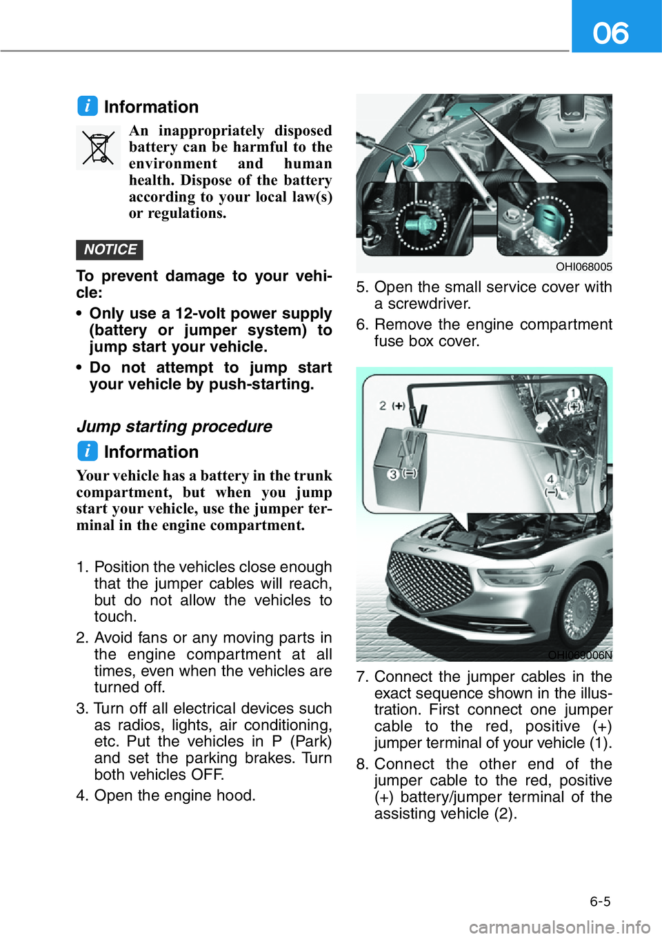
7. Connect the jumper cables in the
exact sequence shown in the illus-
tration. First connect one jumper
cable to the red, positive (+)
jumper terminal of your vehicle (1).
8. Connect the other end of the
jumper cable to the red, positive
(+) battery/jumper terminal of the
assisting vehicle (2).
i
NOTICE
i
OHI069006N
OHI068005
Page 474 of 538
7-34
Maintenance
Battery Usage
Recommendations
• Keep the battery securely mount-
ed.
• Keep the battery top clean and dry.
• Keep the terminals and connec-
tions clean, tight, and coated with
petroleum jelly or terminal grease.
• Rinse any spilled acid from the bat-
tery immediately with a solution of
water and baking soda.
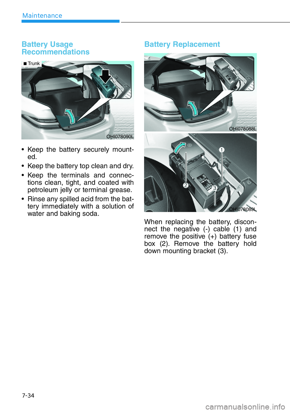
Battery Replacement
When replacing the battery, discon-
nect the negative (-) cable (1) and
remove the positive (+) battery fuse
box (2). Remove the battery hold
down mounting bracket (3).
OHI078090L
■Trunk
OHI078088L
OHI078089L
Page 476 of 538
7-36
Maintenance
By jump starting
After a jump start from a good bat-
tery, drive the vehicle for 20-30 min-
utes before it is shutoff. The vehicle
may not restart if you shut it off
before the battery had a chance to
adequately recharge. See "Jump
Starting" in chapter 6 for more infor-
mation on jump starting procedures.
Information
An inappropriately disposed
battery can be harmful to
the environment and human
health.
Dispose of the battery according to
your local law(s) or regulation.
Reset features
The following items may need to be
reset after the battery has been dis-
charged or the battery has been dis-
connected.
• Seat position memory system (See
chapter 3)
• Auto up/down window (See chap-
ter 3)
• Sunroof (See chapter 3)
• Power trunk (See chapter 3)
• Trip computer (See chapter 3)
• Climate control system (See chap-
ter 3)
• Clock (See AVN manual)
• Rear door window curtain (See
chapter 3)
• AVN system (See AVN manual)
i
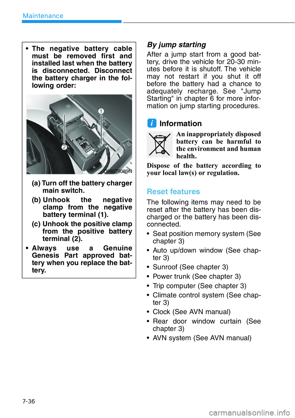
• The negative battery cable
must be removed first and
installed last when the battery
is disconnected. Disconnect
the battery charger in the fol-
lowing order:
(a) Turn off the battery charger
main switch.
(b) Unhook the negative
clamp from the negative
battery terminal (1).
(c) Unhook the positive clamp
from the positive battery
terminal (2).
• Always use a Genuine
Genesis Part approved bat-
tery when you replace the bat-
tery.
OHI079089N
Page 492 of 538
7-52
Maintenance
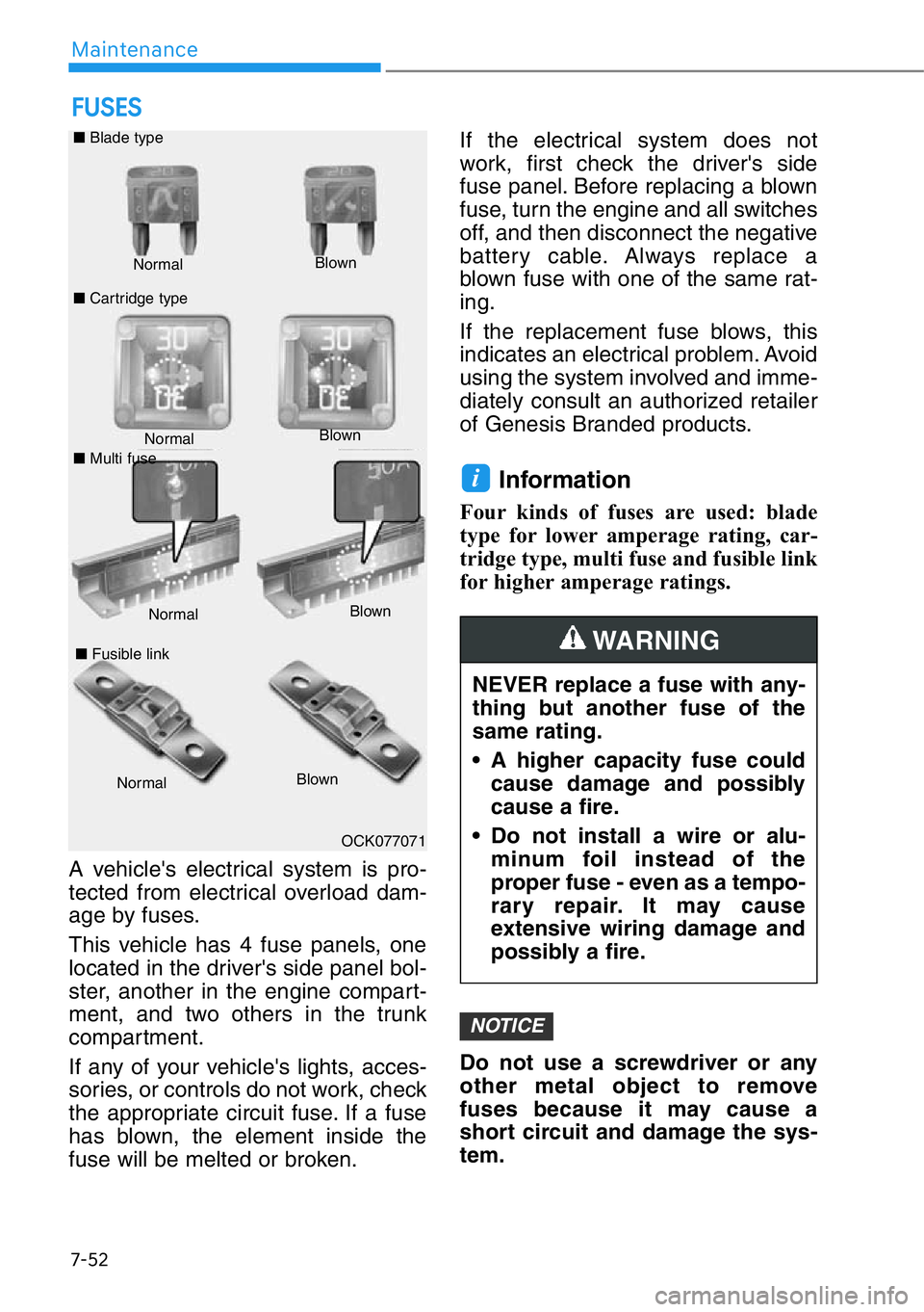
A vehicle's electrical system is pro-
tected from electrical overload dam-
age by fuses.
This vehicle has 4 fuse panels, one
located in the driver's side panel bol-
ster, another in the engine compart-
ment, and two others in the trunk
compartment.
If any of your vehicle's lights, acces-
sories, or controls do not work, check
the appropriate circuit fuse. If a fuse
has blown, the element inside the
fuse will be melted or broken.If the electrical system does not
work, first check the driver's side
fuse panel. Before replacing a blown
fuse, turn the engine and all switches
off, and then disconnect the negative
battery cable. Always replace a
blown fuse with one of the same rat-
ing.
If the replacement fuse blows, this
indicates an electrical problem. Avoid
using the system involved and imme-
diately consult an authorized retailer
of Genesis Branded products.
Information
Four kinds of fuses are used: blade
type for lower amperage rating, car-
tridge type, multi fuse and fusible link
for higher amperage ratings.
Do not use a screwdriver or any
other metal object to remove
fuses because it may cause a
short circuit and damage the sys-
tem.
NOTICE
i
FUSES
Normal Normal ■Blade type
■Cartridge typeBlown
Blown
■Fusible link
NormalBlown
OCK077071
NEVER replace a fuse with any-
thing but another fuse of the
same rating.
• A higher capacity fuse could
cause damage and possibly
cause a fire.
• Do not install a wire or alu-
minum foil instead of the
proper fuse - even as a tempo-
rary repair. It may cause
extensive wiring damage and
possibly a fire.
WARNING
■Multi fuse
NormalBlown
Page 497 of 538

7-57
07
Instrument panel fuse panel
Fuse name Fuse rating Circuit protected
MODULE5 10AStop Lamp Switch, Driver/Passenger Door Module
MODULE7 10A
Electro Chromic Mirror, A/V & Navigation Head Unit, AMP,
A/C Control Module, Front A/C Controller, Air Quality
Sensor, Rear Seat Warmer Control Module LH/RH,
Driver/Passenger CCS Module, Rear CCS Module LH/RH,
Parking Collision Avoidance Assist Unit, Driver/Passenger
IMS Control Module, Rear IMS Control Module LH/RH, Rear
Seat Console Switch, Driver/Passenger Seat Warmer
Control Module
IBU3 10AIBU Control Module
E-SHIFTER2 10AElectronic ATM Shift Lever
MEMORY1 10A
Security Indicator, A/C Control Module, Front A/C Controller,
Instrument Cluster, Driver/Passenger IMS Control Module,
Rear IMS Control Module LH/RH, Head-Up Display, Analog
Clock, Driver/Passenger Seat Control Switch, Power Trunk
Module, Rear Seat Control Switch LH/RH, Driver/Passenger
Smart Key Outside Handle, Rear Smart Key Outside Handle
LH/RH, Blind Spot Collision Warning Unit LH/RH
P/SEAT
(RR LH) 225ARear IMS Control Module LH
P/SEAT
(DRV) 225ADriver IMS Control Module
P/WINDOW (RH)30APassenger Power Window Module, Rear Power Window
Module RH
MODULE 610ACrash Pad Switch, Blind Spot Collision Warning Unit LH/RH,
ECS Unit, Front Console Switch, Front Camera, Steering Tilt
& Telescopic Module
MODULE 10 10ACooling Fan Controller (BLDC), Rear Seat Console Switch,
Surround View Monitor, Parking Collision Avoidance Assist
Unit
MODULE3 10AGATEWAY (B+ (MCU)), Data Link Connector, Hazard
Switch
SUNROOF 25ASunroof Motor
P/SEAT (PASS) 225APassenger IMS Control Module
Page 498 of 538
7-58
Maintenance
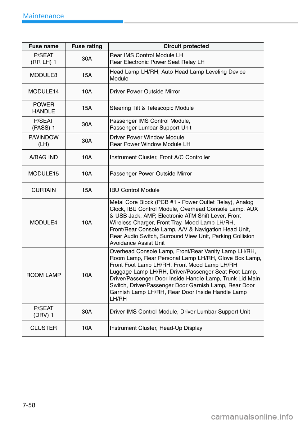
Fuse name Fuse rating Circuit protected
P/SEAT
(RR LH) 130ARear IMS Control Module LH
Rear Electronic Power Seat Relay LH
MODULE8 15AHead Lamp LH/RH, Auto Head Lamp Leveling Device
Module
MODULE1410ADriver Power Outside Mirror
POWER
HANDLE 15ASteering Tilt & Telescopic Module
P/SEAT
(PASS) 130APassenger IMS Control Module,
Passenger Lumbar Support Unit
P/WINDOW
(LH)30ADriver Power Window Module,
Rear Power Window Module LH
A/BAG IND10AInstrument Cluster, Front A/C Controller
MODULE1510APassenger Power Outside Mirror
CURTAIN 15AIBU Control Module
MODULE4 10A
Metal Core Block (PCB #1 - Power Outlet Relay), Analog
Clock, IBU Control Module, Overhead Console Lamp, AUX
& USB Jack, AMP, Electronic ATM Shift Lever, Front
Wireless Charger, Front Tray, Mood Lamp LH/RH,
Front/Rear Console Lamp, A/V & Navigation Head Unit,
Rear Audio Switch, Surround View Unit, Parking Collision
Avoidance Assist Unit
ROOM LAMP 10A
Overhead Console Lamp, Front/Rear Vanity Lamp LH/RH,
Room Lamp, Rear Personal Lamp LH/RH, Glove Box Lamp,
Front Foot Lamp LH/RH, Front Mood Lamp LH/RH
Luggage Lamp LH/RH, Driver/Passenger Seat Foot Lamp,
Driver/Passenger Door Inside Handle Lamp, Trunk Lid Main
Switch, Driver/Passenger Door Garnish Lamp, Rear Door
Garnish Lamp LH/RH, Rear Door Inside Handle Lamp
LH/RH
P/SEAT
(DRV) 130ADriver IMS Control Module, Driver Lumbar Support Unit
CLUSTER 10AInstrument Cluster, Head-Up Display
Page 505 of 538
7-65
07
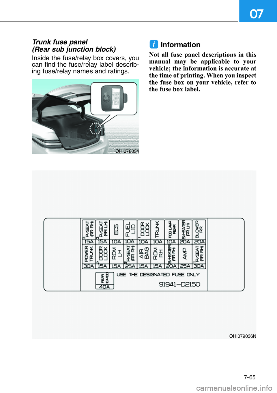
Trunk fuse panel
(Rear sub junction block)
Inside the fuse/relay box covers, you
can find the fuse/relay label describ-
ing fuse/relay names and ratings.
Information
Not all fuse panel descriptions in this
manual may be applicable to your
vehicle; the information is accurate at
the time of printing. When you inspect
the fuse box on your vehicle, refer to
the fuse box label.
i
OHI079036N
OHI078034