engine GENESIS GV80 2021 Owner's Manual
[x] Cancel search | Manufacturer: GENESIS, Model Year: 2021, Model line: GV80, Model: GENESIS GV80 2021Pages: 632, PDF Size: 9.37 MB
Page 593 of 632
Maintenance
9-52
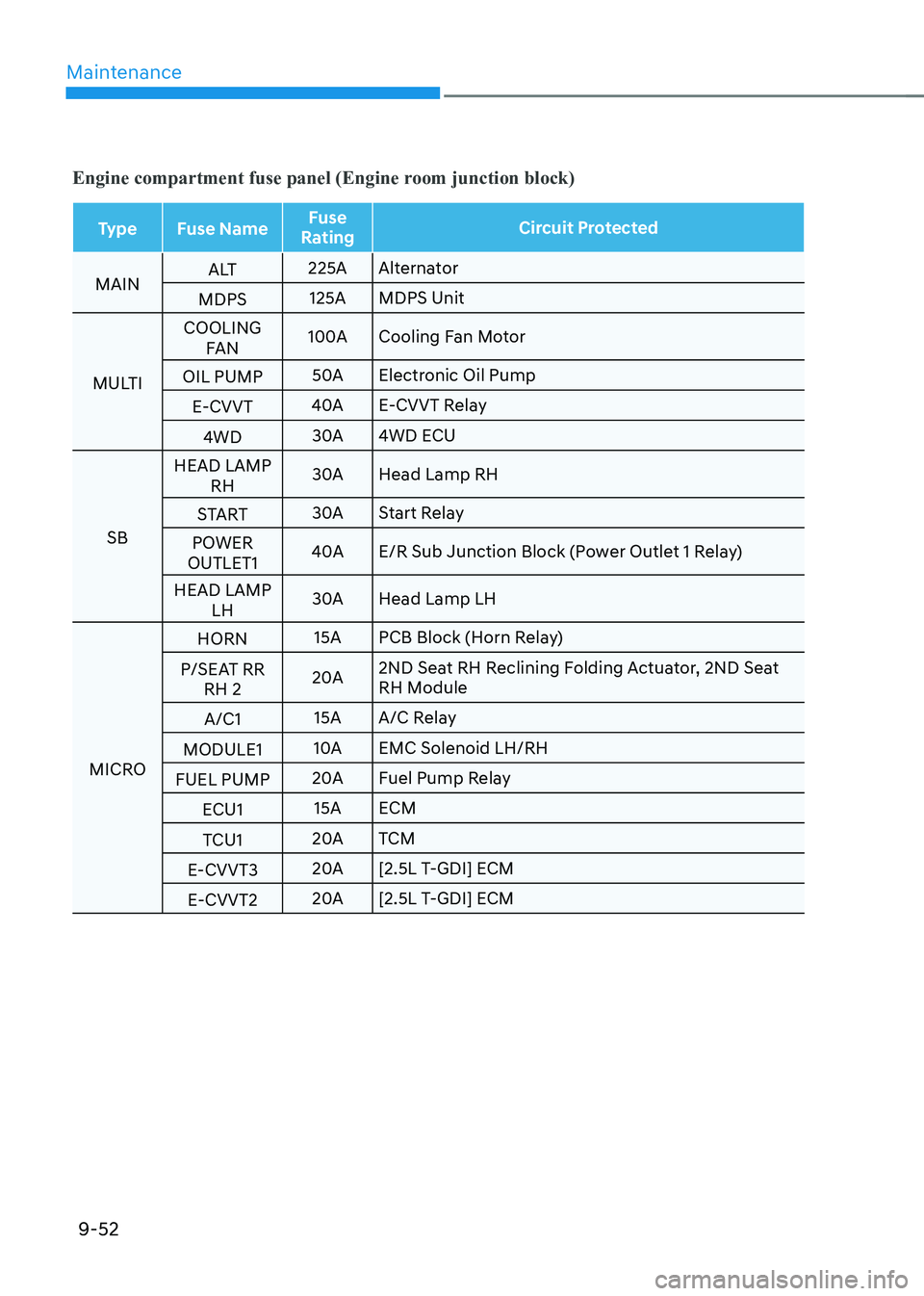
Engine compartment fuse panel (Engine room junction block)
TypeFuse Name Fuse
Rating Circuit Protected
MAIN A LT
225A
Alternator
MDPS 125A
MDPS Unit
MULTI COOLING
FAN 100A
Cooling Fan Motor
OIL PUMP 50A
Electronic Oil Pump
E-CVVT 40A
E-CVVT Relay
4WD 30A
4WD ECU
SB HEAD LAMP
RH 30A
Head Lamp RH
START 30A
Start Relay
POWER
OUTLET1 40A
E/R Sub Junction Block (Power Outlet 1 Relay)
HEAD LAMP LH 30A
Head Lamp LH
MICRO HORN
15A
PCB Block (Horn Relay)
P/SEAT RR RH 2 20A
2ND Seat RH Reclining Folding Actuator, 2ND Seat
RH Module
A/C1 15A
A/C Relay
MODULE1 10A
Solenoid LH/RH
FUEL PUMP 20A
Fuel Pump Relay
ECU1 15A
ECM
TCU1 20A
TCM
E-CVVT3 20A
[2.5L T-GDI] ECM
E-CVVT2 20A
[2.5L T-GDI] ECM
Page 594 of 632
09
9-53
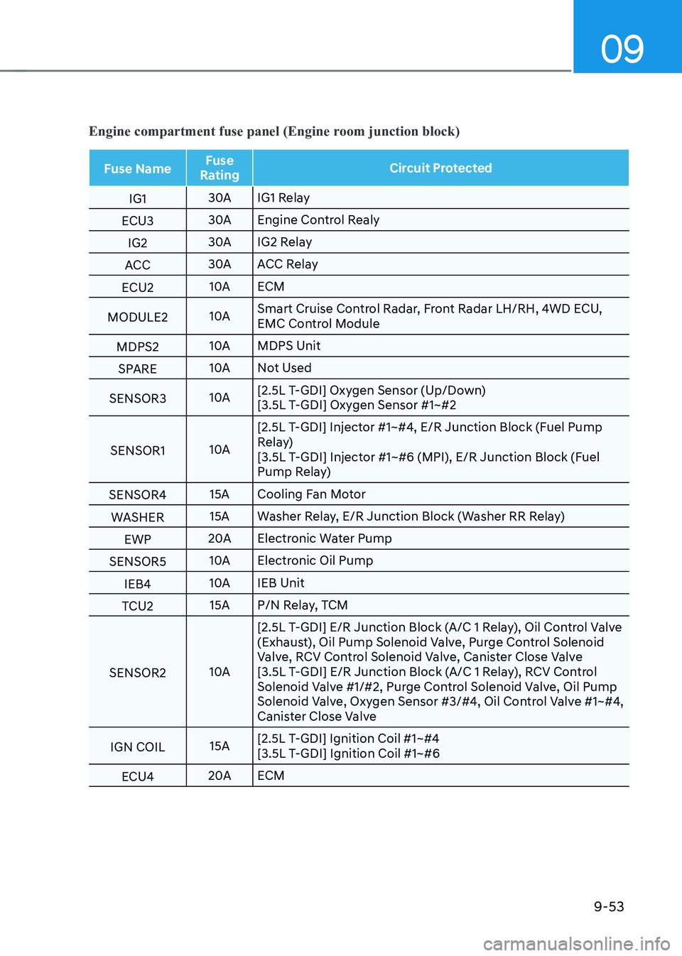
Engine compartment fuse panel (Engine room junction block)
Fuse NameFuse
Rating Circuit Protected
IG1 30A
IG1 Relay
ECU3 30A
Engine Control Realy
IG2 30A
IG2 Relay
ACC 30A
ACC Relay
ECU2 10A
ECM
MODULE2 10ASmart Cruise Control Radar, Front Radar LH/RH, 4WD ECU,
Control Module
MDPS2 10A
MDPS Unit
SPARE 10A
Not Used
SENSOR3 10A[2.5L T-GDI] Oxygen Sensor (Up/Down)
[3.5L T-GDI] Oxygen Sensor #1~#2
SENSOR1 10A[2.5L T-GDI] Injector #1~#4, E/R Junction Block (Fuel Pump
Relay)
[3.5L T-GDI] Injector #1~#6 (MPI), E/R Junction Block (Fuel
Pump Relay)
SENSOR4 15A
Cooling Fan Motor
WASHER 15A
Washer Relay, E/R Junction Block (Washer RR Relay)
EWP 20A
Electronic Water Pump
SENSOR5 10A
Electronic Oil Pump
IEB4 10A
IEB Unit
TCU2 15A
P/N Relay, TCM
SENSOR2 10A[2.5L T-GDI] E/R Junction Block (A/C 1 Relay), Oil Control Valve
(Exhaust), Oil Pump Solenoid Valve, Purge Control Solenoid
Valve, RCV Control Solenoid Valve, Canister Close Valve
[3.5L T-GDI] E/R Junction Block (A/C 1 Relay), RCV Control
Solenoid Valve #1/#2, Purge Control Solenoid Valve, Oil Pump
Solenoid Valve, Oxygen Sensor #3/#4, Oil Control Valve #1~#4,
Canister Close Valve
IGN COIL 15A[2.5L T-GDI] Ignition Coil #1~#4
[3.5L T-GDI] Ignition Coil #1~#6
ECU4 20A
ECM
Page 595 of 632

Maintenance
9-54
Engine compartment fuse panel
(Engine room sub junction block)
OJX1090049NOJX1090049N
Inside the fuse/relay box cover, you can
find the fuse/relay label describing fuse/
relay names and ratings.
Information
Not all fuse panel descriptions in this
manual may be applicable to your vehicle;
the information is accurate at the time of
printing. When you inspect the fuse panel
in your vehicle, refer to the fuse panel
label.
OJX1090048NOJX1090048N
Page 596 of 632
09
9-55
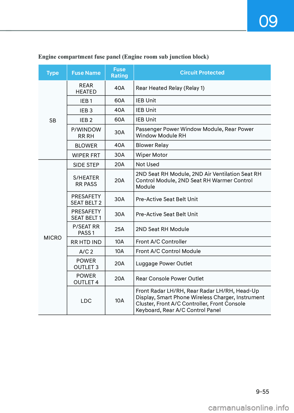
Engine compartment fuse panel (Engine room sub junction block)
TypeFuse Name Fuse
Rating Circuit Protected
SB REAR
HEATED 40A
Rear Heated Relay (Relay 1)
IEB 1 60A
IEB Unit
IEB 3 40A
IEB Unit
IEB 2 60A
IEB Unit
P/WINDOW RR RH 30A
Passenger Power Window Module, Rear Power
Window Module RH
BLOWER 40A
Blower Relay
WIPER FRT 30A
Wiper Motor
MICRO SIDE STEP
20A
Not Used
S/HEATER RR PASS 20A2ND Seat RH Module, 2ND Air Ventilation Seat RH
Control Module, 2ND Seat RH Warmer Control
Module
PRESAFETY
SEAT BELT 2 30A
Pre-Active Seat Belt Unit
PRESAFETY
SEAT BELT 1 30A
Pre-Active Seat Belt Unit
P/SEAT RR PASS 1 25A
2ND Seat RH Module
RR HTD IND 10A
Front A/C Controller
A/C 2 10A
Front A/C Control Module
POWER
OUTLET 3 20A
Luggage Power Outlet
POWER
OUTLET 4 20A
Rear Console Power Outlet
LDC 10AFront Radar LH/RH, Rear Radar LH/RH, Head-Up
Display, Smart Phone Wireless Charger, Instrument
Cluster, Front A/C Controller, Front Console
Keyboard, Rear A/C Control Panel
Page 601 of 632
Maintenance
9-60
Consult an authorized retailer of
Genesis Branded products to replace
most vehicle light bulbs. It is difficult
to replace vehicle light bulbs because
other parts of the vehicle must be
removed before you can get to the bulb.
This is especially true for removing the
headlamp assembly to get to the bulb(s).
Removing/installing the headlamp
assembly can result in damage to the
vehicle.
WARNING
• Prior to working on a light, depress
the foot brake, shift to P (Park), apply
the parking brake, press the Engine
Start/Stop button to the OFF position
and take the key with you when
leaving the vehicle to avoid sudden
movement of the vehicle and to
prevent possible electric shock.
• Be aware the bulbs may be hot and
may burn your fingers.
NOTICE
Be sure to replace the burned-out bulb
with one of the same wattage rating.
Otherwise, it may cause damage to the
fuse or electrical wiring system.
NOTICE
To prevent damage, do not clean the
headlamp lens with chemical solvents
or strong detergents.
Information - Headlamp
desiccant (if equipped)
This vehicle is equipped with desiccant to
reduce fogging inside the headlamp due
to moisture. The desiccant is consumable
and its performance may change based on
the used period or environment. If fogging
inside the headlamp due to moisture
continues for a long time, consult an
authorized retailer of Genesis Branded
products.
Information
The headlamp and tail lamp lenses could
appear frosty if the vehicle is washed after
driving or the vehicle is driven at night in
wet weather. This condition is caused by
temperature difference between the lamp
inside and outside and, it does not indicate
a problem with your vehicle. When
moisture condenses in the lamp, it will be
removed after driving with the headlamp
on. The removable level may differ
depending on lamp size, lamp position
and environmental condition. However, if
moisture is not removed, have the vehicle
inspected by an authorized retailer of
Genesis Branded products.
LIGHT BULBS
Page 608 of 632
09
9-67
NOTICE
• Do not use strong soap, chemical
detergents or hot water, and do not
wash the vehicle in direct sunlight
or when the body of the vehicle is
warm.
• Be careful when washing the side
windows of your vehicle.
• Especially, with high-pressure water,
water may leak through the windows
and wet the interior.
• To prevent damage to the plastic
parts, do not clean with chemical
solvents or strong detergents.
NOTICE
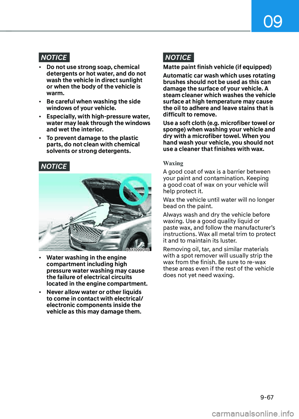
OJX1099040OJX1099040
• Water washing in the engine
compartment including high
pressure water washing may cause
the failure of electrical circuits
located in the engine compartment.
• Never allow water or other liquids
to come in contact with electrical/
electronic components inside the
vehicle as this may damage them.
NOTICE
Matte paint finish vehicle (if equipped)
Automatic car wash which uses rotating
brushes should not be used as this can
damage the surface of your vehicle. A
steam cleaner which washes the vehicle
surface at high temperature may cause
the oil to adhere and leave stains that is
difficult to remove.
Use a soft cloth (e.g. microfiber towel or
sponge) when washing your vehicle and
dry with a microfiber towel. When you
hand wash your vehicle, you should not
use a cleaner that finishes with wax.
Waxing
A good coat of wax is a barrier between
your paint and contamination. Keeping
a good coat of wax on your vehicle will
help protect it.
Wax the vehicle until water will no longer
bead on the paint.
Always wash and dry the vehicle before
waxing. Use a good quality liquid or
paste wax, and follow the manufacturer’s
instructions. Wax all metal trim to protect
it and to maintain its luster.
Removing oil, tar, and similar materials
with a spot remover will usually strip the
wax from the finish. Be sure to re-wax
these areas even if the rest of the vehicle
does not yet need waxing.
Page 616 of 632
09
9-75
The emission control system of your
vehicle is covered by a written limited
warranty. Please see the warranty
information contained in the Owner’s
Handbook & Warranty Information
booklet in your vehicle.
Your vehicle is equipped with an
emission control system to meet all
applicable emission regulations. There
are three emission control systems, as
follows.
(1) Crankcase emission control system
(2) Evaporative emission control system
(3) Exhaust emission control system
In order to ensure the proper function
of the emission control systems, it
is recommended that you have your
vehicle inspected and maintained by an
authorized retailer of Genesis Branded
products in accordance with the
maintenance schedule in this manual.
NOTICE
For the Inspection and Maintenance
Test (with Electronic Stability Control
(ESC) system)
• To prevent the vehicle from misfiring
during dynamometer testing, turn
the Electronic Stability Control
(ESC) system off by pressing the ESC
switch (ESC OFF light illuminated).
• After dynamometer testing is
completed, turn the ESC system back
on by pressing the ESC switch again.
1. Crankcase Emission Control
System
The positive crankcase ventilation system
is employed to prevent air pollution
caused by blow-by gases being emitted
from the crankcase. This system supplies
fresh filtered air to the crankcase through
the air intake hose. Inside the crankcase,
the fresh air mixes with blow-by gases,
which then pass through the PCV valve
into the induction system.
2. Evaporative Emission Control
System including Onboard
Refueling Vapor Recovery
(ORVR)
The Evaporative Emission Control System
is designed to prevent fuel vapors from
escaping into the atmosphere. The
ORVR system is designed to allow the
vapors from the fuel tank to be loaded
into a canister while refueling at the gas
station, preventing the escape of fuel
vapors into the atmosphere.
Canister
Fuel vapors generated inside the fuel
tank are absorbed and stored in the
onboard canister. When the engine is
running, the fuel vapors absorbed in the
canister are drawn into the surge tank
through the purge control solenoid valve.
Purge Control Solenoid Valve (PCSV)
The purge control solenoid valve
is controlled by the Engine Control
Module (ECM); when the engine coolant
temperature is low during idling, the
PCSV closes so that evaporated fuel
is not taken into the engine. After the
engine warms-up during ordinary
driving, the PCSV opens to introduce
evaporated fuel to the engine.
EMISSION CONTROL SYSTEM
Page 617 of 632

Maintenance
9 -76
3. Exhaust Emission Control
System
The Exhaust Emission Control System is
a highly effective system which controls
exhaust emissions while maintaining
good vehicle performance.
When the engine starts or fails to start,
excessive attempts to restart the engine
may cause damage to the emission
system.
Engine exhaust (carbon monoxide)
precautions
• Carbon monoxide can be present
with other exhaust fumes. If you smell
exhaust fumes of any kind in your
vehicle, drive with all the windows
fully open. Have your vehicle checked
and repaired immediately.
WARNING
Engine exhaust gases contain carbon
monoxide (CO). Though colorless and
odorless, it is dangerous and could be
lethal if inhaled. Follow the instructions
on this page to avoid CO poisoning.
WARNING
CALIFORNIA PROPOSITION 65
WARNING
Engine exhaust and a wide variety of
automobile components and parts,
including components found in the
interior furnishings in a vehicle, contain
or emit chemicals known to the State
of California to cause cancer and
birth defects and reproductive harm.
In addition, certain fluids contained
in vehicles and certain products of
component wear contain or emit
chemicals known to the State of
California to cause cancer and birth
defects or other reproductive harm.
• Do not operate the engine in confined
or closed areas (such as garages) any
more than what is necessary to move
the vehicle in or out of the area.
• When the vehicle is stopped in an
open area for more than a short time
with the engine running, adjust the
ventilation system (as needed) to draw
outside air into the vehicle.
• Never sit in a parked or stopped
vehicle for any extended time with the
engine running.
• When the engine stalls or fails to
start, excessive attempts to restart
the engine may cause damage to the
emission control system.
Page 618 of 632

09
9-77
Operating precautions for catalytic
converters (if equipped)
WARNING
The exhaust system and catalytic
converter are very hot during and
immediately after the engine has been
running. To avoid SERIOUS INJURY or
DEATH:
• Do not park, idle, or drive the vehicle
over or near flammable objects, such
as grass, vegetation, paper, leaves,
etc. A hot exhaust system can ignite
flammable items under your vehicle.
• Keep away from the exhaust system
and catalytic converter or you may
get burned.
Also, do not remove the heat sink
around the exhaust system, do not
seal the bottom of the vehicle, and
do not coat the vehicle for corrosion
control. It may present a fire risk
under certain conditions.
Your vehicle is equipped with a catalytic
converter emission control device.
To prevent damage to the catalytic
converter and to your vehicle, take the
following precautions:
• Use only UNLEADED FUEL for
gasoline engines.
• Do not operate the vehicle when
there are signs of engine malfunction,
such as misfire or a noticeable loss of
performance.
• Do not misuse or abuse the engine.
Examples of misuse are coasting with
the engine off and descending steep
grades in gear with the engine off.
• Do not operate the engine at high
idle speed for extended periods (5
minutes or more).
• Do not modify or tamper with any
part of the engine or emission
control system. All inspections and
adjustments must be made by an
authorized retailer of Genesis Branded
products.
• Avoid driving with an extremely low
fuel level.
Running out of fuel could cause the
engine to misfire, damaging the
catalytic converter.
CALIFORNIA PERCHLORATE
NOTICE
Perchlorate Material-special handling
may apply, See: www.dtsc.ca.gov/
hazardouswaste/perchlorate.
Notice to California Vehicle Dismantlers:
Perchlorate containing materials, such as
air bag inflators, seatbelt pretensioners
and keyless remote entry batteries, must
be disposed of according to Title 22
California Code of Regulations Section
67384.10 (a).
Page 623 of 632
I
I-5
E
Electronically Controlled Suspension with Road Preview
..................................6-46
Limitations of the System
........................................................................\
.......6-47
System Malfunction
........................................................................\
................6-47
Electronic Control Suspension
........................................................................\
....6-46
System Malfunction
........................................................................\
................6-46
Electronic Limited Slip Differential
....................................................................6-45
Drive Mode Selection
........................................................................\
.............6-45
Warning Messages ........................................................................\
................... 6-45
Emission Control System
........................................................................\
............9-75
Crankcase Emission Control System
..............................................................9-75
Evaporative Emission Control System including Onboard Refueling Vapor
Recovery (ORVR)
........................................................................\
...................9-75
Exhaust Emission Control System
..................................................................9-76
Engine
........................................................................\
............................................2-8
Engine Compartment
........................................................................\
.....................9-3
Engine Compartment
........................................................................\
.....................2-7
Engine Coolant/Liquid-Cooled Intercooler Coolant
...........................................9-17
Changing Coolant ........................................................................\
.................... 9-19
Checking the Coolant Level
........................................................................\
....9-17
Engine Number
........................................................................\
............................2-15
Engine oil
........................................................................\
.....................................9-15
Checking the Engine Oil and Filter
.................................................................9-16
Checking the Engine Oil Level
.......................................................................9-15
Engine Start/Stop Button
........................................................................\
...............6-6
Engine Stop/Start Button Positions
...................................................................6-7
Remote Start
........................................................................\
............................6-10
Starting the Engine
........................................................................\
....................6-8
Turning Off the Engine
........................................................................\
.............6-9
Explanation of Scheduled Maintenance Items
....................................................9-13
Exterior Features
........................................................................\
........................5-127
Roof Side Rails
........................................................................\
.....................5-127
Exterior Features
........................................................................\
..........................5-62
Fuel Filler Door
........................................................................\
.......................5-71
Hood
........................................................................\
........................................5-62
Power Liftgate
........................................................................\
.........................5-63
Smart Liftgate ........................................................................\
.......................... 5-69