Engine oil GENESIS GV80 2021 Owner's Guide
[x] Cancel search | Manufacturer: GENESIS, Model Year: 2021, Model line: GV80, Model: GENESIS GV80 2021Pages: 632, PDF Size: 9.37 MB
Page 553 of 632
Maintenance
9-12
Severe driving conditions
A. Repeatedly driving short distance of less than 5 miles (8 km) in normal temperature
or less than 10 miles (16 km) in freezing temperature
B. Extensive engine idling or low speed driving for long distances
C. Driving on rough, dusty, muddy, unpaved, graveled or saltspread roads
D. Driving in areas using salt or other corrosive materials or in very cold weather
E. Driving in the condition of inflowing sand or dust into engine
F. Driving in heavy traffic area
G. Driving on uphill, downhill, or mountain roads
H. Towing a trailer (if equipped)
I. Driving for patrol car, taxi, commercial car or vehicle towing
J. Driving over 106 mph (170 km/h)
K. Frequently driving in stop-and-go conditions
L. Engine oil usage which is not recommended (mineral type, lower grade spec, etc.)
Page 554 of 632
09
9-13
Engine Oil and Filter
The engine oil and filter should be
changed at the intervals specified in the
maintenance schedule. If the vehicle
is being driven in severe conditions,
more frequent oil and filter changes are
required.
Drive Belts
Inspect all drive belts for evidence
of cuts, cracks, excessive wear or oil
saturation and replace if necessary.
Drive belts should be checked
periodically for proper tension and
adjusted as necessary.
Information
When you are inspecting the belt, turn the
engine off.
Fuel Lines, Fuel Hoses and
Connections
Check the fuel lines, fuel hoses and
connections for leakage and damage.
Have an authorized retailer of Genesis
Branded products replace any damaged
or leaking parts immediately.
Vapor Hose and Fuel Filler Cap
The vapor hose and fuel filler cap should
be inspected at those intervals specified
in the maintenance schedule. Make sure
a new vapor hose or fuel filler cap is
correctly replaced.
Air Cleaner Filter
We recommend that the air cleaner filter
be replaced by an authorized retailer of
Genesis Branded products.
Spark Plugs
Make sure to install new spark plugs of
the correct heat range.
Cooling System
Check cooling system components, such
as radiator, coolant reservoir, hoses and
connections for leakage and damage.
Replace any damaged parts.
Engine coolant/Liquid-cooled
intercooler coolant
The coolant should be changed at the
intervals specified in the maintenance
schedule.
Automatic transmission fluid
Automatic transmission fluid should
not be checked under normal usage
conditions, the automatic transmission
fluid should be changed by an authorized
retailer of Genesis Branded products
according to the maintenance schedule.
Information
Automatic transmission fluid color is red
when new.
As the vehicle is driven, the automatic
transmission fluid will begin to look
darker.
This is a normal condition. It does not
need to be replaced based on the color
change.
NOTICE
The use of a non-specified fluid could
result in transmission malfunction and
failure.
Use only specified automatic
transmission fluid. (Refer to
“Recommended Lubricants and
Capacities” section in chapter 2.)
EXPLANATION OF SCHEDULED MAINTENANCE ITEMS
Page 556 of 632
09
9-15
ENGINE OIL
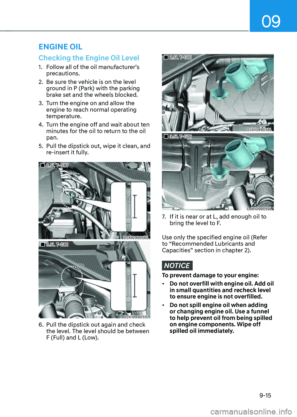
Checking the Engine Oil Level
1. Follow all of the oil manufacturer’s
precautions.
2. Be sure the vehicle is on the level
ground in P (Park) with the parking
brake set and the wheels blocked.
3. Turn the engine on and allow the
engine to reach normal operating
temperature.
4. Turn the engine off and wait about ten
minutes for the oil to return to the oil
pan.
5. Pull the dipstick out, wipe it clean, and
re-insert it fully.
�
Page 557 of 632
Maintenance
9-16
Checking the Engine Oil and
Filter
Have the engine oil and filter changed by an authorized retailer of Genesis Branded
products according to the Maintenance
Schedule at the beginning of this
chapter.
WARNING
CALIFORNIA PROPOSITION 65
WARNING
Engine oil contains chemicals known to
the State of California to cause cancer,
birth defects and reproductive harm.
Used engine oil may cause irritation or
cancer of the skin if left in contact with
the skin for prolonged periods of time.
Always protect your skin by washing
your hands thoroughly with soap and
warm water as soon as possible after
handling used oil.
Page 561 of 632
Maintenance
9-20
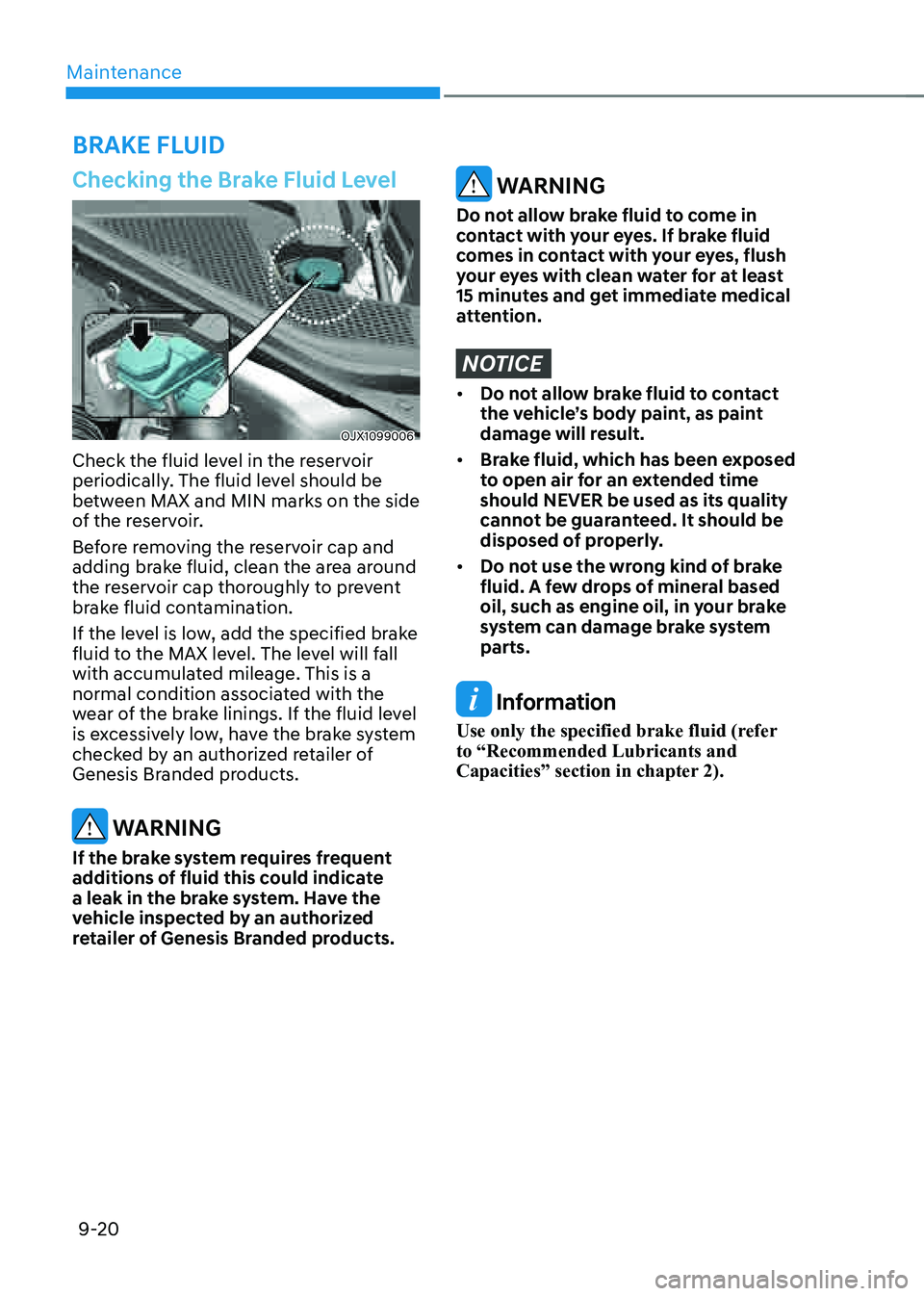
Checking the Brake Fluid Level
OJX1099006OJX1099006
Check the fluid level in the reservoir
periodically. The fluid level should be
between MAX and MIN marks on the side
of the reservoir.
Before removing the reservoir cap and
adding brake fluid, clean the area around
the reservoir cap thoroughly to prevent
brake fluid contamination.
If the level is low, add the specified brake
fluid to the MAX level. The level will fall
with accumulated mileage. This is a
normal condition associated with the
wear of the brake linings. If the fluid level
is excessively low, have the brake system
checked by an authorized retailer of
Genesis Branded products.
WARNING
If the brake system requires frequent
additions of fluid this could indicate
a leak in the brake system. Have the
vehicle inspected by an authorized
retailer of Genesis Branded products.
WARNING
Do not allow brake fluid to come in
contact with your eyes. If brake fluid
comes in contact with your eyes, flush
your eyes with clean water for at least
15 minutes and get immediate medical
attention.
NOTICE
• Do not allow brake fluid to contact
the vehicle’s body paint, as paint
damage will result.
• Brake fluid, which has been exposed
to open air for an extended time
should NEVER be used as its quality
cannot be guaranteed. It should be
disposed of properly.
• Do not use the wrong kind of brake
fluid. A few drops of mineral based
oil, such as engine oil, in your brake
system can damage brake system
parts.
Information
Use only the specified brake fluid (refer
to “Recommended Lubricants and
Capacities” section in chapter 2).
BRAKE FLUID
Page 585 of 632
Maintenance
9-44
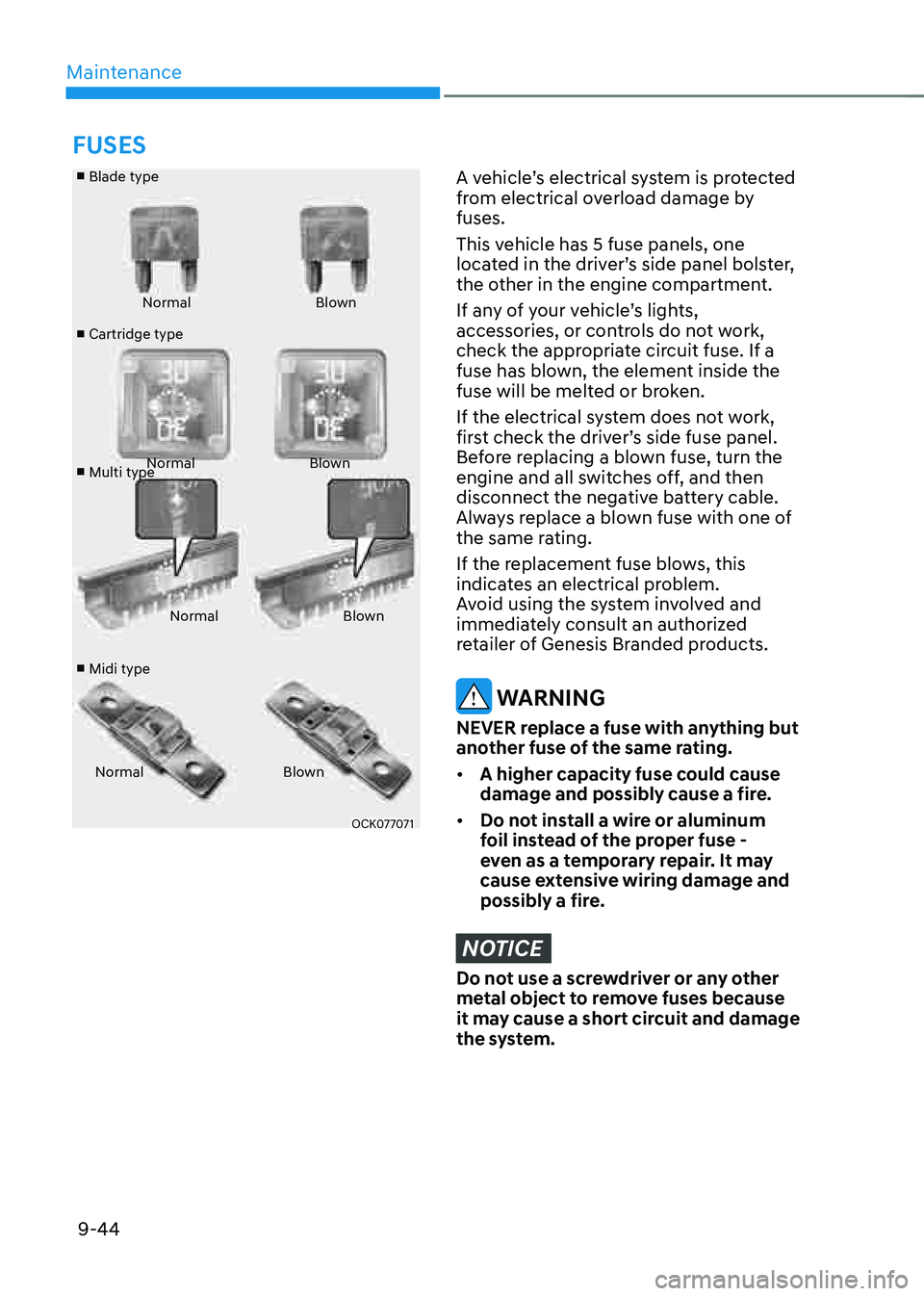
■ Blade type
■ Cartridge type
■ Multi type
■ Midi type Normal
Blown
Normal Blown
Normal Blown
Normal Blown
OCK077071OCK077071
A vehicle’s electrical system is protected
from electrical overload damage by
fuses.
This vehicle has 5 fuse panels, one
located in the driver’s side panel bolster,
the other in the engine compartment.
If any of your vehicle’s lights,
accessories, or controls do not work,
check the appropriate circuit fuse. If a
fuse has blown, the element inside the
fuse will be melted or broken.
If the electrical system does not work,
first check the driver’s side fuse panel.
Before replacing a blown fuse, turn the
engine and all switches off, and then
disconnect the negative battery cable.
Always replace a blown fuse with one of
the same rating.
If the replacement fuse blows, this
indicates an electrical problem.
Avoid using the system involved and
immediately consult an authorized
retailer of Genesis Branded products.
WARNING
NEVER replace a fuse with anything but
another fuse of the same rating.
• A higher capacity fuse could cause
damage and possibly cause a fire.
• Do not install a wire or aluminum
foil instead of the proper fuse -
even as a temporary repair. It may
cause extensive wiring damage and
possibly a fire.
NOTICE
Do not use a screwdriver or any other
metal object to remove fuses because
it may cause a short circuit and damage
the system.
FUSES
Page 593 of 632
Maintenance
9-52
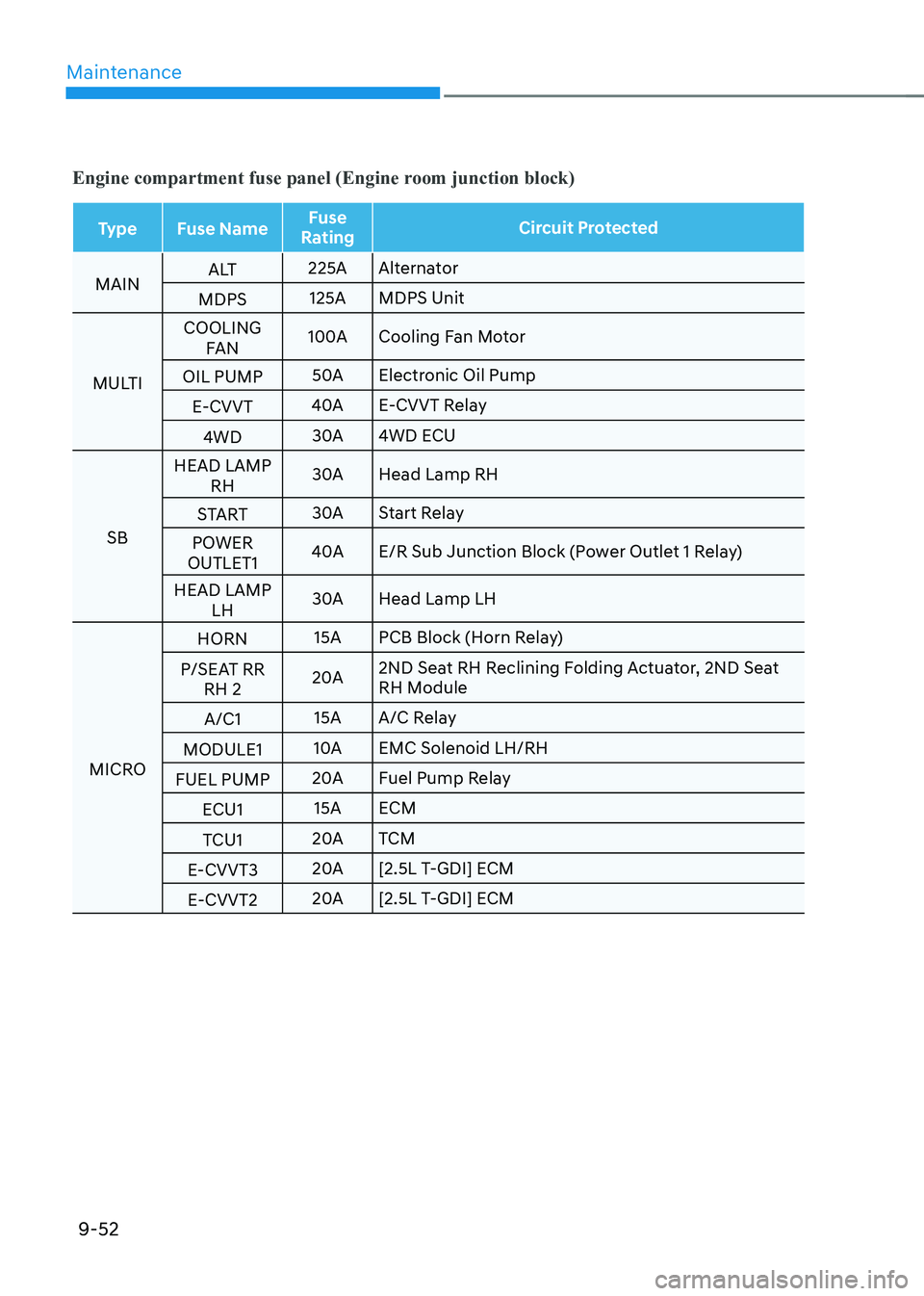
Engine compartment fuse panel (Engine room junction block)
TypeFuse Name Fuse
Rating Circuit Protected
MAIN A LT
225A
Alternator
MDPS 125A
MDPS Unit
MULTI COOLING
FAN 100A
Cooling Fan Motor
OIL PUMP 50A
Electronic Oil Pump
E-CVVT 40A
E-CVVT Relay
4WD 30A
4WD ECU
SB HEAD LAMP
RH 30A
Head Lamp RH
START 30A
Start Relay
POWER
OUTLET1 40A
E/R Sub Junction Block (Power Outlet 1 Relay)
HEAD LAMP LH 30A
Head Lamp LH
MICRO HORN
15A
PCB Block (Horn Relay)
P/SEAT RR RH 2 20A
2ND Seat RH Reclining Folding Actuator, 2ND Seat
RH Module
A/C1 15A
A/C Relay
MODULE1 10A
Solenoid LH/RH
FUEL PUMP 20A
Fuel Pump Relay
ECU1 15A
ECM
TCU1 20A
TCM
E-CVVT3 20A
[2.5L T-GDI] ECM
E-CVVT2 20A
[2.5L T-GDI] ECM
Page 594 of 632
09
9-53
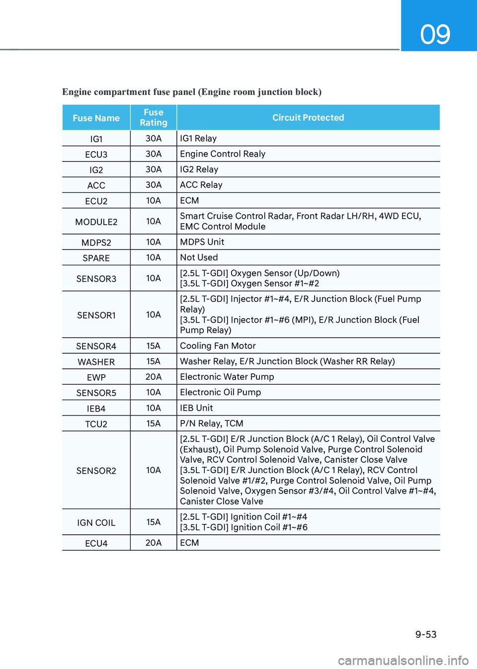
Engine compartment fuse panel (Engine room junction block)
Fuse NameFuse
Rating Circuit Protected
IG1 30A
IG1 Relay
ECU3 30A
Engine Control Realy
IG2 30A
IG2 Relay
ACC 30A
ACC Relay
ECU2 10A
ECM
MODULE2 10ASmart Cruise Control Radar, Front Radar LH/RH, 4WD ECU,
Control Module
MDPS2 10A
MDPS Unit
SPARE 10A
Not Used
SENSOR3 10A[2.5L T-GDI] Oxygen Sensor (Up/Down)
[3.5L T-GDI] Oxygen Sensor #1~#2
SENSOR1 10A[2.5L T-GDI] Injector #1~#4, E/R Junction Block (Fuel Pump
Relay)
[3.5L T-GDI] Injector #1~#6 (MPI), E/R Junction Block (Fuel
Pump Relay)
SENSOR4 15A
Cooling Fan Motor
WASHER 15A
Washer Relay, E/R Junction Block (Washer RR Relay)
EWP 20A
Electronic Water Pump
SENSOR5 10A
Electronic Oil Pump
IEB4 10A
IEB Unit
TCU2 15A
P/N Relay, TCM
SENSOR2 10A[2.5L T-GDI] E/R Junction Block (A/C 1 Relay), Oil Control Valve
(Exhaust), Oil Pump Solenoid Valve, Purge Control Solenoid
Valve, RCV Control Solenoid Valve, Canister Close Valve
[3.5L T-GDI] E/R Junction Block (A/C 1 Relay), RCV Control
Solenoid Valve #1/#2, Purge Control Solenoid Valve, Oil Pump
Solenoid Valve, Oxygen Sensor #3/#4, Oil Control Valve #1~#4,
Canister Close Valve
IGN COIL 15A[2.5L T-GDI] Ignition Coil #1~#4
[3.5L T-GDI] Ignition Coil #1~#6
ECU4 20A
ECM
Page 608 of 632
09
9-67
NOTICE
• Do not use strong soap, chemical
detergents or hot water, and do not
wash the vehicle in direct sunlight
or when the body of the vehicle is
warm.
• Be careful when washing the side
windows of your vehicle.
• Especially, with high-pressure water,
water may leak through the windows
and wet the interior.
• To prevent damage to the plastic
parts, do not clean with chemical
solvents or strong detergents.
NOTICE
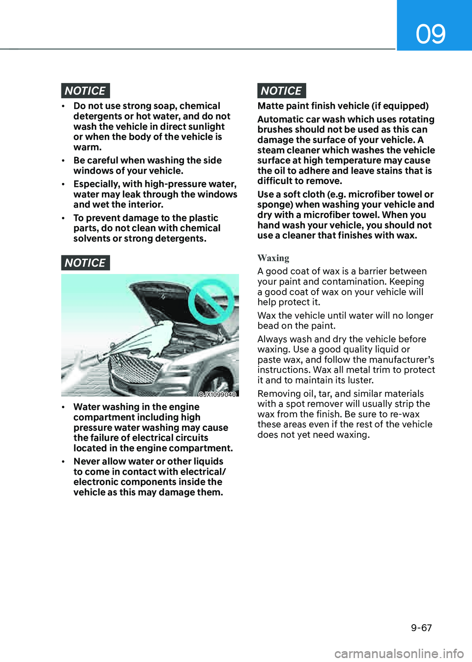
OJX1099040OJX1099040
• Water washing in the engine
compartment including high
pressure water washing may cause
the failure of electrical circuits
located in the engine compartment.
• Never allow water or other liquids
to come in contact with electrical/
electronic components inside the
vehicle as this may damage them.
NOTICE
Matte paint finish vehicle (if equipped)
Automatic car wash which uses rotating
brushes should not be used as this can
damage the surface of your vehicle. A
steam cleaner which washes the vehicle
surface at high temperature may cause
the oil to adhere and leave stains that is
difficult to remove.
Use a soft cloth (e.g. microfiber towel or
sponge) when washing your vehicle and
dry with a microfiber towel. When you
hand wash your vehicle, you should not
use a cleaner that finishes with wax.
Waxing
A good coat of wax is a barrier between
your paint and contamination. Keeping
a good coat of wax on your vehicle will
help protect it.
Wax the vehicle until water will no longer
bead on the paint.
Always wash and dry the vehicle before
waxing. Use a good quality liquid or
paste wax, and follow the manufacturer’s
instructions. Wax all metal trim to protect
it and to maintain its luster.
Removing oil, tar, and similar materials
with a spot remover will usually strip the
wax from the finish. Be sure to re-wax
these areas even if the rest of the vehicle
does not yet need waxing.
Page 623 of 632
I
I-5
E
Electronically Controlled Suspension with Road Preview
..................................6-46
Limitations of the System
........................................................................\
.......6-47
System Malfunction
........................................................................\
................6-47
Electronic Control Suspension
........................................................................\
....6-46
System Malfunction
........................................................................\
................6-46
Electronic Limited Slip Differential
....................................................................6-45
Drive Mode Selection
........................................................................\
.............6-45
Warning Messages ........................................................................\
................... 6-45
Emission Control System
........................................................................\
............9-75
Crankcase Emission Control System
..............................................................9-75
Evaporative Emission Control System including Onboard Refueling Vapor
Recovery (ORVR)
........................................................................\
...................9-75
Exhaust Emission Control System
..................................................................9-76
Engine
........................................................................\
............................................2-8
Engine Compartment
........................................................................\
.....................9-3
Engine Compartment
........................................................................\
.....................2-7
Engine Coolant/Liquid-Cooled Intercooler Coolant
...........................................9-17
Changing Coolant ........................................................................\
.................... 9-19
Checking the Coolant Level
........................................................................\
....9-17
Engine Number
........................................................................\
............................2-15
Engine oil
........................................................................\
.....................................9-15
Checking the Engine Oil and Filter
.................................................................9-16
Checking the Engine Oil Level
.......................................................................9-15
Engine Start/Stop Button
........................................................................\
...............6-6
Engine Stop/Start Button Positions
...................................................................6-7
Remote Start
........................................................................\
............................6-10
Starting the Engine
........................................................................\
....................6-8
Turning Off the Engine
........................................................................\
.............6-9
Explanation of Scheduled Maintenance Items
....................................................9-13
Exterior Features
........................................................................\
........................5-127
Roof Side Rails
........................................................................\
.....................5-127
Exterior Features
........................................................................\
..........................5-62
Fuel Filler Door
........................................................................\
.......................5-71
Hood
........................................................................\
........................................5-62
Power Liftgate
........................................................................\
.........................5-63
Smart Liftgate ........................................................................\
.......................... 5-69