oil pressure GMC ACADIA 2010 Owner's Manual
[x] Cancel search | Manufacturer: GMC, Model Year: 2010, Model line: ACADIA, Model: GMC ACADIA 2010Pages: 444, PDF Size: 2.58 MB
Page 5 of 444
Introduction v
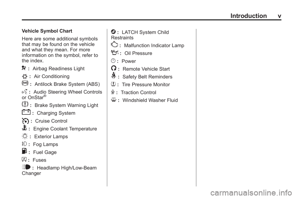
Vehicle Symbol Chart
Here are some additional symbols
that may be found on the vehicle
and what they mean. For more
information on the symbol, refer to
the index.
9:Airbag Readiness Light
#:Air Conditioning
!:Antilock Brake System (ABS)
g:Audio Steering Wheel Controls
or OnStar®
$: Brake System Warning Light
":Charging System
I:Cruise Control
B: Engine Coolant Temperature
O:Exterior Lamps
#:Fog Lamps
.: Fuel Gage
+:Fuses
i: Headlamp High/Low-Beam
Changer
j: LATCH System Child
Restraints
*: Malfunction Indicator Lamp
::Oil Pressure
}:Power
/:Remote Vehicle Start
>:Safety Belt Reminders
7:Tire Pressure Monitor
F:Traction Control
M:Windshield Washer Fluid
Page 7 of 444
In Brief 1-1
In Brief
Instrument Panel
Instrument Panel . . . . . . . . . . . . . . 1-2
Initial Drive Information
Initial Drive Information . . . . . . . . 1-4
Remote Keyless Entry (RKE)System . . . . . . . . . . . . . . . . . . . . . . 1-4
Remote Vehicle Start . . . . . . . . . 1-4
Door Locks . . . . . . . . . . . . . . . . . . . 1-5
Liftgate . . . . . . . . . . . . . . . . . . . . . . . . 1-5
Windows . . . . . . . . . . . . . . . . . . . . . . 1-6
Seat Adjustment . . . . . . . . . . . . . . 1-6
Second Row Seats . . . . . . . . . . . 1-7
Third Row Seats . . . . . . . . . . . . . . 1-7
Heated Seats . . . . . . . . . . . . . . . . . 1-8
Heated and Ventilated Seats . . . . . . . . . . . . . . . . . . . . . . . . 1-8
Head Restraint Adjustment . . . . 1-8
Safety Belt . . . . . . . . . . . . . . . . . . . . 1-8
Sensing System for Passenger Airbag . . . . . . . . . . . . . . . . . . . . . . . 1-9
Mirror Adjustment . . . . . . . . . . . . . 1-9
Steering Wheel Adjustment . . . . . . . . . . . . . . . . . 1-10
Interior Lighting . . . . . . . . . . . . . . 1-10 Exterior Lighting . . . . . . . . . . . . . 1-11
Windshield Wiper/Washer . . . . 1-11
Climate Controls . . . . . . . . . . . . . 1-12
Vehicle Features
Radio(s) . . . . . . . . . . . . . . . . . . . . . 1-14
Satellite Radio . . . . . . . . . . . . . . . 1-15
Portable Audio Devices . . . . . . 1-15
Bluetooth
®. . . . . . . . . . . . . . . . . . . 1-15
Steering Wheel Controls . . . . . 1-16
Navigation System . . . . . . . . . . . 1-16
Cruise Control . . . . . . . . . . . . . . . 1-17
Storage Compartments . . . . . . 1-17
Power Outlets . . . . . . . . . . . . . . . 1-18
Sunroof . . . . . . . . . . . . . . . . . . . . . . 1-18
Performance and Maintenance
StabiliTrak®. . . . . . . . . . . . . . . . . . 1-18
Tire Pressure Monitor . . . . . . . . 1-19
Tire Sealant and Compressor Kit . . . . . . . . . . . . . 1-19
Engine Oil Life System . . . . . . 1-19
Driving for Better Fuel Economy . . . . . . . . . . . . . . . . . . . 1-20
Roadside Assistance Program . . . . . . . . . . . . . . . . . . . . 1-20
OnStar
®. . . . . . . . . . . . . . . . . . . . . 1-21
Page 25 of 444
In Brief 1-19
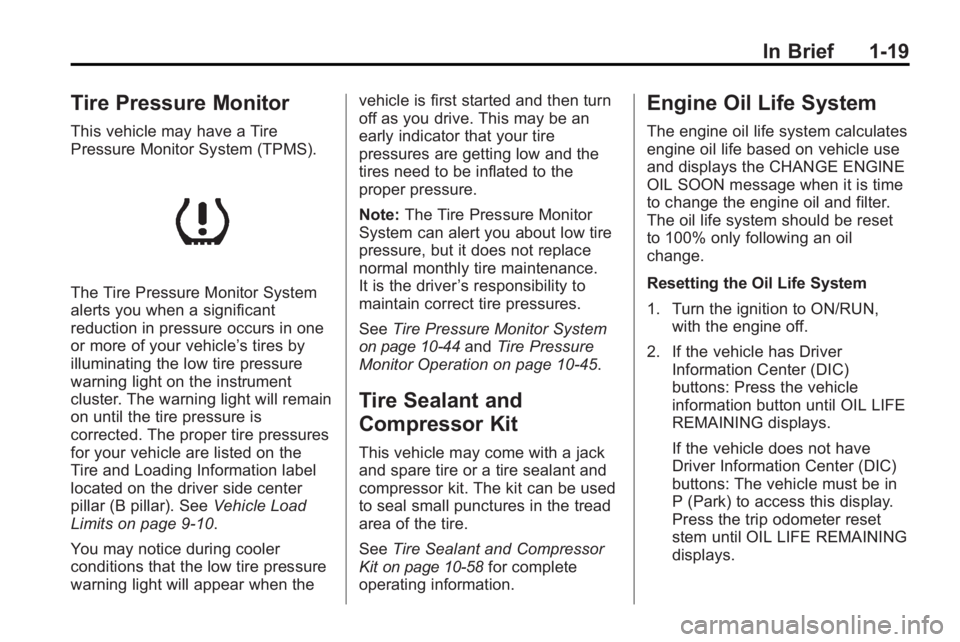
Tire Pressure Monitor
This vehicle may have a Tire
Pressure Monitor System (TPMS).
The Tire Pressure Monitor System
alerts you when a significant
reduction in pressure occurs in one
or more of your vehicle’s tires by
illuminating the low tire pressure
warning light on the instrument
cluster. The warning light will remain
on until the tire pressure is
corrected. The proper tire pressures
for your vehicle are listed on the
Tire and Loading Information label
located on the driver side center
pillar (B pillar). SeeVehicle Load
Limits on page 9‑10.
You may notice during cooler
conditions that the low tire pressure
warning light will appear when the vehicle is first started and then turn
off as you drive. This may be an
early indicator that your tire
pressures are getting low and the
tires need to be inflated to the
proper pressure.
Note:
The Tire Pressure Monitor
System can alert you about low tire
pressure, but it does not replace
normal monthly tire maintenance.
It is the driver ’s responsibility to
maintain correct tire pressures.
See Tire Pressure Monitor System
on page 10‑44andTire Pressure
Monitor Operation on page 10‑45.
Tire Sealant and
Compressor Kit
This vehicle may come with a jack
and spare tire or a tire sealant and
compressor kit. The kit can be used
to seal small punctures in the tread
area of the tire.
See Tire Sealant and Compressor
Kit
on page 10‑58for complete
operating information.
Engine Oil Life System
The engine oil life system calculates
engine oil life based on vehicle use
and displays the CHANGE ENGINE
OIL SOON message when it is time
to change the engine oil and filter.
The oil life system should be reset
to 100% only following an oil
change.
Resetting the Oil Life System
1. Turn the ignition to ON/RUN, with the engine off.
2. If the vehicle has Driver Information Center (DIC)
buttons: Press the vehicle
information button until OIL LIFE
REMAINING displays.
If the vehicle does not have
Driver Information Center (DIC)
buttons: The vehicle must be in
P (Park) to access this display.
Press the trip odometer reset
stem until OIL LIFE REMAINING
displays.
Page 34 of 444
2-6 Keys, Doors and Windows
Extending Engine Run Time
To extend the engine run time by
10 minutes, repeat Steps 1 though 3
while the engine is still running. The
engine run time can only be
extended if it is the first remote start
since the vehicle has been driven.
Remote start can be extended
one time.
If the remote start procedure is
used again before the first
10 minute time frame has ended,
the first 10 minutes will immediately
expire and the second 10 minute
time frame will start.
For example, if the lock button and
then the remote start buttons are
pressed again after the vehicle has
been running for five minutes,
10 minutes are added, allowing the
engine to run for a total of
15 minutes.A maximum of two remote starts or
remote start attempts are allowed
between ignition cycles.
After the vehicle's engine has been
started two times using the remote
start button, the ignition must be
turned on and then back off before
the remote start procedure can be
used again.
Shutting the Engine Off After a
Remote Start
To manually shut off a remote start:
.Aim the RKE transmitter at the
vehicle and press
/until the
parking lamps turn off.
.Turn on the hazard warning
flashers.
.Turn the ignition switch on and
then off.
Conditions in Which the
Remote Start Will Not Work
The vehicle cannot be started using
the remote start feature if the key is
in the ignition, the hood is open, or if
there is an emission control system
malfunction.
The engine turns off during a remote
start if the coolant temperature gets
too high or if the oil pressure
gets low.
Vehicles that have the remote
vehicle start feature are shipped
from the factory with the remote
vehicle start system enabled. The
system may be enabled or disabled
through the DIC if the vehicle has
DIC buttons. See “REMOTE
START” underVehicle
Personalization (With DIC Buttons)
on page 5‑44for additional
information. If the vehicle does not
have DIC buttons, see your dealer/
retailer to enable or disable the
remote start system.
Page 119 of 444
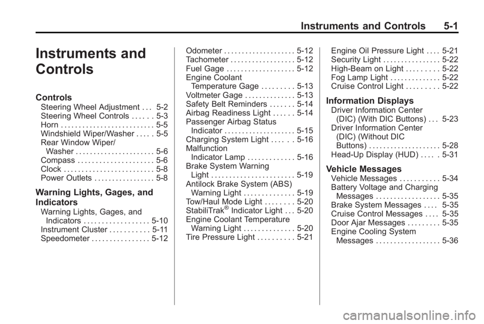
Instruments and Controls 5-1
Instruments and
Controls
Controls
Steering Wheel Adjustment . . . 5-2
Steering Wheel Controls . . . . . . 5-3
Horn . . . . . . . . . . . . . . . . . . . . . . . . . . 5-5
Windshield Wiper/Washer . . . . . 5-5
Rear Window Wiper/Washer . . . . . . . . . . . . . . . . . . . . . . 5-6
Compass . . . . . . . . . . . . . . . . . . . . . 5-6
Clock . . . . . . . . . . . . . . . . . . . . . . . . . 5-8
Power Outlets . . . . . . . . . . . . . . . . . 5-8
Warning Lights, Gages, and
Indicators
Warning Lights, Gages, and Indicators . . . . . . . . . . . . . . . . . . 5-10
Instrument Cluster . . . . . . . . . . . 5-11
Speedometer . . . . . . . . . . . . . . . . 5-12 Odometer . . . . . . . . . . . . . . . . . . . . 5-12
Tachometer . . . . . . . . . . . . . . . . . . 5-12
Fuel Gage . . . . . . . . . . . . . . . . . . . 5-12
Engine Coolant
Temperature Gage . . . . . . . . . 5-13
Voltmeter Gage . . . . . . . . . . . . . . 5-13
Safety Belt Reminders . . . . . . . 5-14
Airbag Readiness Light . . . . . . 5-14
Passenger Airbag Status Indicator . . . . . . . . . . . . . . . . . . . . 5-15
Charging System Light . . . . . . 5-16
Malfunction Indicator Lamp . . . . . . . . . . . . . 5-16
Brake System Warning Light . . . . . . . . . . . . . . . . . . . . . . . 5-19
Antilock Brake System (ABS) Warning Light . . . . . . . . . . . . . . 5-19
Tow/Haul Mode Light . . . . . . . . 5-20
StabiliTrak®Indicator Light . . . 5-20
Engine Coolant Temperature Warning Light . . . . . . . . . . . . . . 5-20
Tire Pressure Light . . . . . . . . . . 5-21 Engine Oil Pressure Light . . . . 5-21
Security Light . . . . . . . . . . . . . . . . 5-22
High-Beam on Light . . . . . . . . . 5-22
Fog Lamp Light . . . . . . . . . . . . . . 5-22
Cruise Control Light . . . . . . . . . 5-22
Information Displays
Driver Information Center
(DIC) (With DIC Buttons) . . . 5-23
Driver Information Center (DIC) (Without DIC
Buttons) . . . . . . . . . . . . . . . . . . . . 5-28
Head-Up Display (HUD) . . . . . 5-31
Vehicle Messages
Vehicle Messages . . . . . . . . . . . 5-34
Battery Voltage and Charging Messages . . . . . . . . . . . . . . . . . . 5-35
Brake System Messages . . . . 5-35
Cruise Control Messages . . . . 5-35
Door Ajar Messages . . . . . . . . . 5-35
Engine Cooling System Messages . . . . . . . . . . . . . . . . . . 5-36
Page 139 of 444
Instruments and Controls 5-21
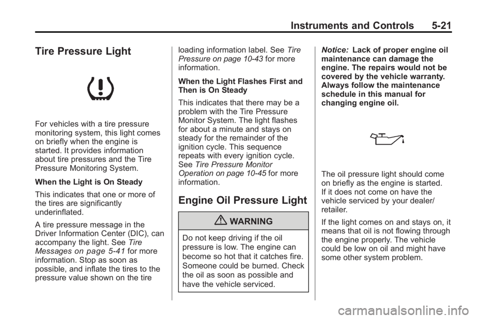
Tire Pressure Light
For vehicles with a tire pressure
monitoring system, this light comes
on briefly when the engine is
started. It provides information
about tire pressures and the Tire
Pressure Monitoring System.
When the Light is On Steady
This indicates that one or more of
the tires are significantly
underinflated.
A tire pressure message in the
Driver Information Center (DIC), can
accompany the light. SeeTire
Messages
on page 5‑41for more
information. Stop as soon as
possible, and inflate the tires to the
pressure value shown on the tire loading information label. See
Tire
Pressure
on page 10‑43for more
information.
When the Light Flashes First and
Then is On Steady
This indicates that there may be a
problem with the Tire Pressure
Monitor System. The light flashes
for about a minute and stays on
steady for the remainder of the
ignition cycle. This sequence
repeats with every ignition cycle.
See Tire Pressure Monitor
Operation
on page 10‑45for more
information.
Engine Oil Pressure Light
{WARNING
Do not keep driving if the oil
pressure is low. The engine can
become so hot that it catches fire.
Someone could be burned. Check
the oil as soon as possible and
have the vehicle serviced. Notice:
Lack of proper engine oil
maintenance can damage the
engine. The repairs would not be
covered by the vehicle warranty.
Always follow the maintenance
schedule in this manual for
changing engine oil.
The oil pressure light should come
on briefly as the engine is started.
If it does not come on have the
vehicle serviced by your dealer/
retailer.
If the light comes on and stays on, it
means that oil is not flowing through
the engine properly. The vehicle
could be low on oil and might have
some other system problem.
Page 141 of 444
Instruments and Controls 5-23
Information Displays
Driver Information Center
(DIC) (With DIC Buttons)
If your vehicle has DIC buttons, the
information below explains the
operation of this system.
The DIC displays information about
your vehicle. It also displays
warning messages if a system
problem is detected.
All messages will appear in the DIC
display located at the top of the
instrument panel cluster.
The DIC comes on when the ignition
is on. After a short delay, the DIC
will display the information that was
last displayed before the engine
was turned off.
The DIC also displays a shift lever
position indicator on the bottom line
of the display. SeeAutomatic
Transmission
on page 9‑22for
more information. The outside air temperature and
compass, if equipped, also display
on the DIC when viewing the trip
and fuel information. The outside air
temperature automatically appears
in the top right corner of the DIC
display. If there is a problem with
the system that controls the
temperature display, the numbers
will be replaced with dashes. If this
occurs, have the vehicle serviced.
The compass will be shown in the
bottom right corner of the DIC
display. See
Compass
on
page 5‑6for more information.
The DIC has different displays
which can be accessed by pressing
the DIC buttons located on the
instrument panel.
The DIC also allows some features
to be customized. See Vehicle
Personalization (With DIC Buttons)
on page 5‑44for more information.
If your vehicle has DIC buttons, you
can also use the trip odometer reset
stem to view the odometer and trip
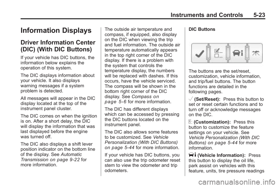
odometers. DIC Buttons
The buttons are the set/reset,
customization, vehicle information,
and trip/fuel buttons. The button
functions are detailed in the
following pages.
V(Set/Reset):
Press this button to
set or reset certain functions and to
turn off or acknowledge messages
on the DIC.
U(Customization): Press this
button to customize the feature
settings on your vehicle. See
Vehicle Personalization (With DIC
Buttons)
on page 5‑44for more
information.
T(Vehicle Information): Press
this button to display the oil life,
park assist on vehicles with this
feature, units, tire pressure readings
Page 156 of 444
5-38 Instruments and Controls
OIL PRESSURE LOW STOP
ENGINE
Notice:If you drive your vehicle
while the engine oil pressure is
low, severe engine damage may
occur. If a low oil pressure
warning appears on the
instrument panel cluster and/or
DIC, stop the vehicle as soon as
possible. Do not drive the vehicle
until the cause of the low oil
pressure is corrected. See Engine
Oil
on page 10‑8for more
information.
This message displays if low oil
pressure levels occur. Stop the
vehicle as soon as safely possible
and do not operate it until the cause
of the low oil pressure has been
corrected. Check the oil as soon as
possible and have your vehicle
serviced by your dealer/retailer. See
Engine Oil on page 10‑8.
Engine Power Messages
ENGINE POWER IS REDUCED
This message displays and a chime
sounds when the cooling system
temperature gets too hot and the
engine further enters the engine
coolant protection mode. See
Engine Overheating
on page 10‑19for further information.
This message also displays when
the vehicle's engine power is
reduced. Reduced engine power
can affect the vehicle's ability to
accelerate. If this message is on,
but there is no reduction in
performance, proceed to your
destination. The performance may
be reduced the next time the vehicle
is driven. The vehicle may be driven
at a reduced speed while this
message is on, but acceleration and
speed may be reduced. Anytime
this message stays on, the vehicle
should be taken to your dealer/
retailer for service as soon as
possible.
Fuel System Messages
FUEL LEVEL LOW
This message displays and a chime
sounds if the fuel level is low. Refuel
as soon as possible. See Fuel Gage
on page 5‑12andFuelon
page 9‑39for more information.
TIGHTEN GAS CAP
This message may display along
with the check engine light on the
instrument panel cluster if the
vehicle's fuel cap is not tightened
properly. See Malfunction Indicator
Lamp
on page 5‑16. Reinstall the
fuel cap fully. See Filling the Tank
on page 9‑42. The diagnostic
system can determine if the fuel cap
has been left off or improperly
installed. A loose or missing fuel
cap allows fuel to evaporate into the
atmosphere. A few driving trips with
the cap properly installed should
turn this light and message off.
Page 313 of 444
Vehicle Care 10-7
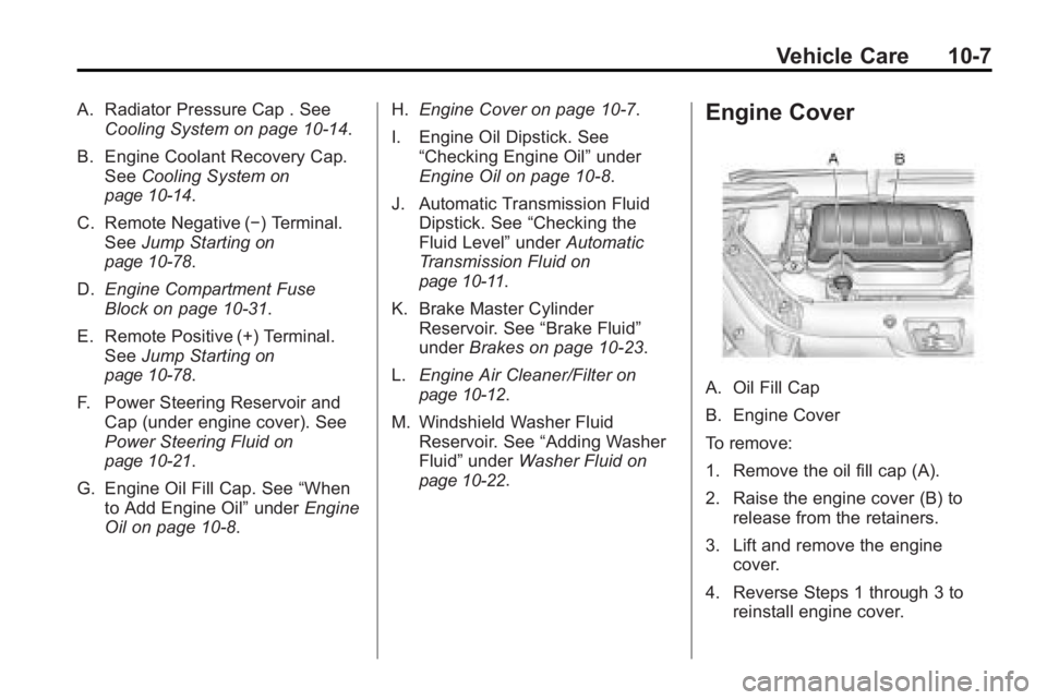
A. Radiator Pressure Cap . SeeCooling System on page 10‑14.
B. Engine Coolant Recovery Cap. See Cooling System
on
page 10‑14.
C. Remote Negative (−) Terminal. See Jump Starting
on
page 10‑78.
D. Engine Compartment Fuse
Block on page 10‑31.
E. Remote Positive (+) Terminal. See Jump Starting
on
page 10‑78.
F. Power Steering Reservoir and Cap (under engine cover). See
Power Steering Fluid
on
page 10‑21.
G. Engine Oil Fill Cap. See “When
to Add Engine Oil” underEngine
Oil on page 10‑8. H.
Engine Cover on page 10‑7.
I. Engine Oil Dipstick. See “Checking Engine Oil” under
Engine Oil on page 10‑8.
J. Automatic Transmission Fluid Dipstick. See “Checking the
Fluid Level” underAutomatic
Transmission Fluid
on
page 10‑11.
K. Brake Master Cylinder Reservoir. See “Brake Fluid”
under Brakes on page 10‑23.
L. Engine Air Cleaner/Filter
on
page 10‑12.
M. Windshield Washer Fluid Reservoir. See “Adding Washer
Fluid” under Washer Fluid
on
page 10‑22.
Engine Cover
A. Oil Fill Cap
B. Engine Cover
To remove:
1. Remove the oil fill cap (A).
2. Raise the engine cover (B) to release from the retainers.
3. Lift and remove the engine cover.
4. Reverse Steps 1 through 3 to reinstall engine cover.
Page 347 of 444
Vehicle Care 10-41
Curb Weight:The weight of a
motor vehicle with standard and
optional equipment including the
maximum capacity of fuel, oil,
and coolant, but without
passengers and cargo.
DOT Markings
:A code molded
into the sidewall of a tire
signifying that the tire is in
compliance with the U.S.
Department of Transportation
(DOT) motor vehicle safety
standards. The DOT code
includes the Tire Identification
Number (TIN), an alphanumeric
designator which can also
identify the tire manufacturer,
production plant, brand, and
date of production.
GVWR
:Gross Vehicle Weight
Rating. See Vehicle Load Limits
on page 9‑10. GAWR FRT
:Gross Axle Weight
Rating for the front axle. See
Vehicle Load Limits
on
page 9‑10
.
GAWR RR
:Gross Axle Weight
Rating for the rear axle. See
Vehicle Load Limits
on
page 9‑10
.
Intended Outboard Sidewall
:
The side of an asymmetrical tire,
that must always face outward
when mounted on a vehicle.
Kilopascal (kPa)
:The metric
unit for air pressure.
Light Truck (LT-Metric) Tire
:A
tire used on light duty trucks and
some multipurpose passenger
vehicles.
Load Index
:An assigned
number ranging from 1 to 279
that corresponds to the load
carrying capacity of a tire. Maximum Inflation Pressure
:
The maximum air pressure to
which a cold tire can be inflated.
The maximum air pressure is
molded onto the sidewall.
Maximum Load Rating
:The
load rating for a tire at the
maximum permissible inflation
pressure for that tire.
Maximum Loaded Vehicle
Weight
:The sum of curb
weight, accessory weight,
vehicle capacity weight, and
production options weight.
Normal Occupant Weight
:The
number of occupants a vehicle
is designed to seat multiplied by
68 kg (150 lbs). See Vehicle
Load Limits
on page 9‑10.
Occupant Distribution
:
Designated seating positions.