ignition GMC CANYON 2018 Get To Know Guide
[x] Cancel search | Manufacturer: GMC, Model Year: 2018, Model line: CANYON, Model: GMC CANYON 2018Pages: 417, PDF Size: 5.47 MB
Page 248 of 417
GMC Canyon/Canyon Denali Owner Manual (GMNA-Localizing-U.S./Canada-
11354423) - 2018 - crc - 10/12/17
Driving and Operating 247
.Press the clutch pedal for
several seconds or shift the
transmission to N (Neutral).
. To turn off cruise control,
press
5.
Erasing Speed Memory
The cruise control set speed is
erased from memory if
5is pressed
or if the ignition is turned off.
Driver Assistance
Systems
Rear Vision
Camera (RVC)
{Warning
The camera(s) do not display
children, pedestrians, bicyclists,
crossing traffic, animals, or any
other object outside of the
cameras’ field of view, below the
bumper, or under the vehicle.
Shown distances may be different
from actual distances. Do not
drive or park the vehicle using
only these camera(s). Always
check behind and around the
vehicle before driving. Failure to
use proper care may result in
injury, death, or vehicle damage.
The RVC system is designed to
help the driver when backing up by
displaying a view of the area behind
the vehicle. When the ignition is on and the driver shifts the vehicle into
R (Reverse), the video image
automatically appears on the
infotainment screen. The
infotainment screen goes to the
previous screen after approximately
four seconds once the vehicle is
shifted out of R (Reverse).
To see the previous screen sooner,
do one of the following:
.
Press a hard key on the
infotainment system.
. Shift into P (Park).
The RVC will not work properly if
the tailgate is down. If the tailgate is
down, do not use this system.
Guidelines
The RVC system may have a
guideline overlay that can help the
driver align the vehicle when
backing into a parking spot.
To turn the guidelines on or off: 1. Shift into P (Park).
2. Touch SETTINGS on the Home Page of the infotainment
display.
Page 265 of 417
GMC Canyon/Canyon Denali Owner Manual (GMNA-Localizing-U.S./Canada-
11354423) - 2018 - crc - 10/12/17
264 Driving and Operating
Operating the vehicle in Tow/Haul
when lightly loaded or with no trailer
at all will not cause damage.
However, there is no benefit to the
selection of Tow/Haul when the
vehicle is unloaded. Such a
selection when unloaded may result
in unpleasant engine and
transmission driving characteristics
and reduced fuel economy. Tow/
Haul is recommended only when
pulling a heavy trailer or a large or
heavy load.
If the vehicle has a diesel engine,
the Tow/Haul button activates the
exhaust brake system
simultaneously. See“Exhaust
Brake” in the Duramax diesel
supplement.
Integrated Trailer Brake
Control System
The vehicle may have an Integrated
Trailer Brake Control (ITBC) system
for use with electric trailer brakes or
most electric over hydraulic trailer
brakes.
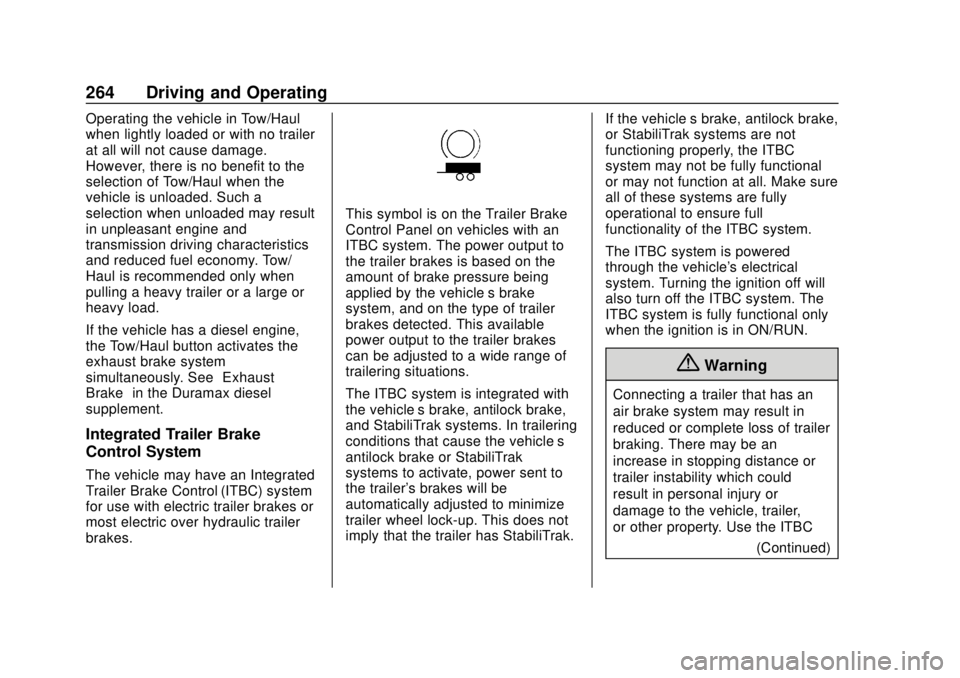
This symbol is on the Trailer Brake
Control Panel on vehicles with an
ITBC system. The power output to
the trailer brakes is based on the
amount of brake pressure being
applied by the vehicle’s brake
system, and on the type of trailer
brakes detected. This available
power output to the trailer brakes
can be adjusted to a wide range of
trailering situations.
The ITBC system is integrated with
the vehicle’ s brake, antilock brake,
and StabiliTrak systems. In trailering
conditions that cause the vehicle’s
antilock brake or StabiliTrak
systems to activate, power sent to
the trailer's brakes will be
automatically adjusted to minimize
trailer wheel lock-up. This does not
imply that the trailer has StabiliTrak. If the vehicle’s brake, antilock brake,
or StabiliTrak systems are not
functioning properly, the ITBC
system may not be fully functional
or may not function at all. Make sure
all of these systems are fully
operational to ensure full
functionality of the ITBC system.
The ITBC system is powered
through the vehicle's electrical
system. Turning the ignition off will
also turn off the ITBC system. The
ITBC system is fully functional only
when the ignition is in ON/RUN.
{Warning
Connecting a trailer that has an
air brake system may result in
reduced or complete loss of trailer
braking. There may be an
increase in stopping distance or
trailer instability which could
result in personal injury or
damage to the vehicle, trailer,
or other property. Use the ITBC
(Continued)
Page 268 of 417

GMC Canyon/Canyon Denali Owner Manual (GMNA-Localizing-U.S./Canada-
11354423) - 2018 - crc - 10/12/17
Driving and Operating 267
Other ITBC-Related DIC Messages
In addition to displaying TRAILER
GAIN and OUTPUT through the
DIC, trailer connection and ITBC
system status are displayed on
the DIC.
TRAILER CONNECTED: This
message will briefly display when a
trailer with electric brakes is first
connected to the vehicle. This
message will automatically turn off
in about 10 seconds. This message
can be acknowledged before it
automatically turns off.
CHECK TRAILER WIRING: This
message will display if:
.The ITBC system first
determines connection to a
trailer with electric brakes and
then the trailer harness becomes
disconnected from the vehicle.
If the disconnect occurs while
the vehicle is stationary, this
message will automatically turn
off in about 30 seconds. This
message will also turn off if it is
acknowledged or if the trailer
harness is reconnected. If the disconnect occurs while
the vehicle is moving, this
message will continue until the
ignition is turned off. This
message will also turn off if it is
acknowledged or if the trailer
harness is reconnected.
. There is an electrical fault in the
wiring to the trailer brakes. This
message will continue as long
as there is an electrical fault in
the trailer wiring. This message
will also turn off if it is
acknowledged.
To determine if the electrical fault is
on the vehicle side or trailer side of
the trailer wiring harness
connection: 1. Disconnect the trailer wiring harness from the vehicle.
2. Turn the ignition off.
3. Wait 10 seconds, then turn the ignition back to RUN.
4. If the CHECK TRAILER WIRING message reappears,
the electrical fault is on the
vehicle side. If the CHECK TRAILER
WIRING message only
reappears when connecting the
trailer wiring harness to the
vehicle, the electrical fault is on
the trailer side.
SERVICE TRAILER BRAKE
SYSTEM: This message will display
when there is a problem with the
ITBC system. If this message
continues over multiple ignition
cycles, there is a problem with the
ITBC system. Have the vehicle
serviced.
If either the CHECK TRAILER
WIRING or SERVICE TRAILER
BRAKE SYSTEM message displays
while driving, the ITBC system may
not be fully functional or may not
function at all. When traffic
conditions allow, carefully pull the
vehicle over to the side of the road
and turn the ignition off. Check the
wiring connection to the trailer and
turn the ignition back on. If either of
these messages continues, either
the vehicle or trailer needs service.
Page 272 of 417
GMC Canyon/Canyon Denali Owner Manual (GMNA-Localizing-U.S./Canada-
11354423) - 2018 - crc - 10/12/17
Vehicle Care 271
Vehicle Care
General Information
General Information . . . . . . . . . . 272
California Proposition65 Warning . . . . . . . . . . . . . . . . . 272
California Perchlorate Materials Requirements . . . . . 273
Accessories and Modifications . . . . . . . . . . . . . . . . 273
Vehicle Checks
Doing Your OwnService Work . . . . . . . . . . . . . . . 273
Hood . . . . . . . . . . . . . . . . . . . . . . . . . 274
Engine Compartment Overview . . . . . . . . . . . . . . . . . . . . 275
Engine Oil . . . . . . . . . . . . . . . . . . . . 278
Engine Oil Life System . . . . . . . 280
Automatic Transmission Fluid . . . . . . . . . . . . . . . . . . . . . . . . 282
Manual Transmission Fluid . . . 282
Hydraulic Clutch . . . . . . . . . . . . . . 282
Engine Air Cleaner/Filter . . . . . . 283
Cooling System . . . . . . . . . . . . . . 284
Engine Overheating . . . . . . . . . . 288
Engine Fan . . . . . . . . . . . . . . . . . . . 289
Washer Fluid . . . . . . . . . . . . . . . . . 290
Brakes . . . . . . . . . . . . . . . . . . . . . . . 290 Brake Fluid . . . . . . . . . . . . . . . . . . . 291
Battery - North America . . . . . . 292
Four-Wheel Drive . . . . . . . . . . . . . 293
Front Axle . . . . . . . . . . . . . . . . . . . . 294
Rear Axle . . . . . . . . . . . . . . . . . . . . 294
Starter Switch Check . . . . . . . . . 295
Automatic Transmission Shift
Lock Control Function
Check . . . . . . . . . . . . . . . . . . . . . . . 296
Ignition Transmission Lock Check . . . . . . . . . . . . . . . . . . . . . . . 296
Park Brake and P (Park) Mechanism Check . . . . . . . . . . 296
Wiper Blade Replacement . . . . 297
Windshield Replacement . . . . . 297
Gas Strut(s) . . . . . . . . . . . . . . . . . . 297
Headlamp Aiming
Headlamp Aiming . . . . . . . . . . . . 299
Bulb Replacement
Bulb Replacement . . . . . . . . . . . . 299
Halogen Bulbs . . . . . . . . . . . . . . . . 299
Headlamps, Front Turn Signal, Sidemarker, and Parking
Lamps . . . . . . . . . . . . . . . . . . . . . . 299
Taillamps, Turn Signal, Stoplamps, and Back-Up
Lamps . . . . . . . . . . . . . . . . . . . . . . 300 Center High-Mounted
Stoplamp (CHMSL) and
Cargo Lamp . . . . . . . . . . . . . . . . . 301
Electrical System
Electrical System Overload . . . 302
Fuses and Circuit Breakers . . . 302
Engine Compartment FuseBlock . . . . . . . . . . . . . . . . . . . . . . . . 303
Instrument Panel Fuse Block . . . . . . . . . . . . . . . . . . . . . . . . 307
Wheels and Tires
Tires . . . . . . . . . . . . . . . . . . . . . . . . . . 309
All-Season Tires . . . . . . . . . . . . . . 310
Winter Tires . . . . . . . . . . . . . . . . . . 310
All-Terrain Tires . . . . . . . . . . . . . . . 311
Tire Sidewall Labeling . . . . . . . . 311
Tire Designations . . . . . . . . . . . . . 313
Tire Terminology andDefinitions . . . . . . . . . . . . . . . . . . 314
Tire Pressure . . . . . . . . . . . . . . . . . 317
Tire Pressure Monitor System . . . . . . . . . . . . . . . . . . . . . . 318
Tire Pressure Monitor Operation . . . . . . . . . . . . . . . . . . . 319
Tire Inspection . . . . . . . . . . . . . . . . 322
Tire Rotation . . . . . . . . . . . . . . . . . 322
When It Is Time for New Tires . . . . . . . . . . . . . . . . . . . . . . . . 323
Buying New Tires . . . . . . . . . . . . . 324
Page 297 of 417

GMC Canyon/Canyon Denali Owner Manual (GMNA-Localizing-U.S./Canada-
11354423) - 2018 - crc - 10/12/17
296 Vehicle Care
Automatic Transmission
Shift Lock Control
Function Check
{Warning
When you are doing this
inspection, the vehicle could
move suddenly. If the vehicle
moves, you or others could be
injured.
1. Before starting this check, be sure there is enough room
around the vehicle. It should be
parked on a level surface.
2. Apply the parking brake. Be ready to apply the regular
brake immediately if the vehicle
begins to move.
3. With the engine off, turn the ignition on, but do not start the
engine. Without applying the
regular brake, try to move the
shift lever out of P (Park) with normal effort. If the shift lever
moves out of P (Park), contact
your dealer for service.
Ignition Transmission
Lock Check
While parked, and with the parking
brake set, try to turn the ignition off
in each shift lever position.
.
For automatic transmission
vehicles, the ignition should turn
to off only when the shift lever is
in P (Park).
. For manual transmission
vehicles, the ignition should turn
off only when you press the key
release button.
On all vehicles, the ignition key
should come out only when the
ignition is off.
Contact your dealer if service is
required.
Park Brake and P (Park)
Mechanism Check
{Warning
When you are doing this check,
the vehicle could begin to move.
You or others could be injured
and property could be damaged.
Make sure there is room in front
of the vehicle in case it begins to
roll. Be ready to apply the regular
brake at once should the vehicle
begin to move.
Park on a fairly steep hill, with the
vehicle facing downhill. Keeping
your foot on the regular brake, set
the parking brake.
. To check the parking brake's
holding ability: With the engine
running and the transmission in
N (Neutral), slowly remove foot
pressure from the regular brake
pedal. Do this until the vehicle is
held by the parking brake only.
Page 306 of 417
GMC Canyon/Canyon Denali Owner Manual (GMNA-Localizing-U.S./Canada-
11354423) - 2018 - crc - 10/12/17
Vehicle Care 305
The vehicle may not be equipped
with all of the fuses, relays, and
features shown.Fuses Usage
F1 Traction control module power
F2 Engine control module power
F3 Air conditioning clutch
F4 –
F5 Engine control module/Integrated
chassis control
module/Fuel pump
power module
F6 Wipers
F7 Cargo lamp/Bed lighting (if
equipped)
F8 Fuel injectors–even
F9 Fuel injectors–odd
F10 Engine control module 1 Fuses Usage
F11 Miscellaneous 1/ Ignition
F12 Starter
F13 Traction control module
F14 –
F15 –
F16 –
F17 Front axle actuator
F18 –
F19 Aeroshutters
F20 –
F21 Front blower
F22 Antilock brake system valves
F23 –
F24 Trailer
F25 Transfer case electronic control
F26 Antilock brake system pump Fuses Usage
F27 Trailer brake control module (if
equipped)/Trailer
wiring
F28 Rear window defogger
F29 –
F30 Driver heated seat
F31 –
F32 Passenger heated seat
F33 Body control module 3
F34 Fuel system control module
F35 Integrated chassis control module (if
equipped)
F36 Center high-mounted
stoplamp
F37 Right high-beam headlamp
Page 307 of 417

GMC Canyon/Canyon Denali Owner Manual (GMNA-Localizing-U.S./Canada-
11354423) - 2018 - crc - 10/12/17
306 Vehicle Care
FusesUsage
F38 Left high-beam headlamp
F39 –
F40 –
F41 –
F42 –
F43 Cooling fan
F44 Vacuum pump
F45 –
F46 Engine control module 2
F47 Miscellaneous 2/ Ignition
F48 Fog lamps (if equipped)
F49 –
F50 Trailer parking lamps
F51 Horn
F52 –
F53 – Fuses
Usage
F54 –
F55 –
F56 Washer pump
F57 –
F58 –
F59 –
F60 Mirrors defogger
F61 –
F62 Canister vent solenoid
F63 –
F64 Trailer reverse lamp
F65 Left trailer stoplamp/Turn
signal lamps
F66 Right trailer stoplamp/Turn
signal lamps
F67 Electric power steering
F68 – Fuses
Usage
F69 Battery regulated voltage control
F70 –
F71 –
F72 –
F73 –
F74 Generator
F75 –
Relays Usage
K1 Air conditioning clutch
K2 Starter
K3 –
K4 Wipers speed
K5 Wipers control
K6 Cargo lamp/Bed lighting (if
equipped)
K7 Powertrain
K8 –
Page 310 of 417
GMC Canyon/Canyon Denali Owner Manual (GMNA-Localizing-U.S./Canada-
11354423) - 2018 - crc - 10/12/17
Vehicle Care 309
FusesUsage
F21 –
F22 –
F23 Data link connector/USB
F24 HVAC ignition
F25 Body control module 7
F26 –
F27 –
F28 Instrument panel/ Sensing and
diagnostic module/
Ignition
F29 Miscellaneous/Ignition
F30 –
F31 Front camera
F32 Steering wheel controls backlighting
F33 Heated steering wheel
F34 Front ventilated seats
F35 Park/Reverse/Neutral/ Drive/Low/Wireless
charging module Fuses
Usage
F36 Discrete logic ignition sensor
F37 –
F38 –
F39 Auxiliary power outlet 2
F40 Auxiliary power outlet
F41 Auxiliary power outlet 1/Lighter
F42 Left power window
F43 Driver power seat
F44 –
F45 Right power window
F46 Passenger power seat
Relays Usage
K1 Retained accessory power
K2 Run/CrankWheels and Tires
Tires
Every new GM vehicle has
high-quality tires made by a
leading tire manufacturer. See
the warranty manual for
information regarding the tire
warranty and where to get
service. For additional
information refer to the tire
manufacturer.
{Warning
.Poorly maintained and
improperly used tires are
dangerous.
.Overloading the tires can
cause overheating as a
result of too much
flexing. There could be a
blowout and a serious
crash. See Vehicle Load
Limits 0211.
(Continued)
Page 320 of 417
GMC Canyon/Canyon Denali Owner Manual (GMNA-Localizing-U.S./Canada-
11354423) - 2018 - crc - 10/12/17
Vehicle Care 319
the TPMS from functioning properly.
Always check the TPMS malfunction
telltale after replacing one or more
tires or wheels on your vehicle to
ensure that the replacement or
alternate tires and wheels allow the
TPMS to continue to function
properly.
SeeTire Pressure Monitor
Operation 0319.
See Radio Frequency Statement
0 388.
Tire Pressure Monitor
Operation
This vehicle may have a Tire
Pressure Monitor System (TPMS).
The TPMS is designed to warn the
driver when a low tire pressure
condition exists. TPMS sensors are
mounted onto each tire and wheel
assembly, excluding the spare tire
and wheel assembly. The TPMS
sensors monitor the air pressure in
the tires and transmit the tire
pressure readings to a receiver
located in the vehicle.
When a low tire pressure condition
is detected, the TPMS illuminates
the low tire pressure warning light
located on the instrument cluster.
If the warning light comes on, stop
as soon as possible and inflate the
tires to the recommended pressure
shown on the Tire and Loading
Information label. See Vehicle Load
Limits 0211.
A message to check the pressure in
a specific tire displays in the Driver
Information Center (DIC). The low
tire pressure warning light and the
DIC warning message come on at
each ignition cycle until the tires are
inflated to the correct inflation
pressure. Using the DIC, tire
pressure levels can be viewed. For
additional information and details
about the DIC operation and displays, see
Driver Information
Center (DIC) (Base Level) 0129 or
Driver Information Center (DIC)
(Uplevel) 0131.
The low tire pressure warning light
may come on in cool weather when
the vehicle is first started, and then
turn off as the vehicle is driven. This
could be an early indicator that the
air pressure is getting low and
needs to be inflated to the proper
pressure.
A Tire and Loading Information label
shows the size of the original
equipment tires and the correct
inflation pressure for the tires when
they are cold. See Vehicle Load
Limits 0211, for an example of the
Tire and Loading Information label
and its location. Also see Tire
Pressure 0317.
The TPMS can warn about a low
tire pressure condition but it does
not replace normal tire
maintenance. See Tire Inspection
0 322, Tire Rotation 0322, and
Tires 0309.
Page 321 of 417
GMC Canyon/Canyon Denali Owner Manual (GMNA-Localizing-U.S./Canada-
11354423) - 2018 - crc - 10/12/17
320 Vehicle Care
Caution
Tire sealant materials are not all
the same. A non-approved tire
sealant could damage the TPMS
sensors. TPMS sensor damage
caused by using an incorrect tire
sealant is not covered by the
vehicle warranty. Always use only
the GM approved tire sealant
available through your dealer or
included in the vehicle.
TPMS Malfunction Light and
Message
The TPMS will not function properly
if one or more of the TPMS sensors
are missing or inoperable. When the
system detects a malfunction, the
low tire pressure warning light
flashes for about one minute and
then stays on for the remainder of
the ignition cycle. A DIC warning
message also displays. The
malfunction light and DIC warning
message come on at each ignitioncycle until the problem is corrected.
Some of the conditions that can
cause these to come on are:
.
One of the road tires has been
replaced with the spare tire. The
spare tire does not have a
TPMS sensor. The malfunction
light and the DIC message
should go off after the road tire
is replaced and the sensor
matching process is performed
successfully. See “TPMS Sensor
Matching Process” later in this
section.
. The TPMS sensor matching
process was not done or not
completed successfully after
rotating the tires. The
malfunction light and the DIC
message should go off after
successfully completing the
sensor matching process. See
“TPMS Sensor Matching
Process” later in this section.
. One or more TPMS sensors are
missing or damaged. The
malfunction light and the DIC
message should go off when the
TPMS sensors are installed and the sensor matching process is
performed successfully. See
your dealer for service.
. Replacement tires or wheels do
not match the original equipment
tires or wheels. Tires and wheels
other than those recommended
could prevent the TPMS from
functioning properly. See Buying
New Tires 0324.
. Operating electronic devices or
being near facilities using radio
wave frequencies similar to the
TPMS could cause the TPMS
sensors to malfunction.
If the TPMS is not functioning
properly, it cannot detect or signal a
low tire pressure condition. See
your dealer for service if the TPMS
malfunction light and DIC message
come on and stay on.
TPMS Sensor Matching
Process
Each TPMS sensor has a unique
identification code. The identification
code needs to be matched to a new
tire/wheel position after rotating the
vehicle’s tires or replacing one or