tow bar GMC SIERRA DENALI 2010 Owners Manual
[x] Cancel search | Manufacturer: GMC, Model Year: 2010, Model line: SIERRA DENALI, Model: GMC SIERRA DENALI 2010Pages: 550, PDF Size: 4.17 MB
Page 154 of 550
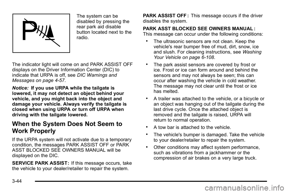
The system can be
disabled by pressing the
rear park aid disable
button located next to the
radio.
The indicator light will come on and PARK ASSIST OFF
displays on the Driver Information Center (DIC) to
indicate that URPA is off, see DIC Warnings and
Messages on page 4‑57.
Notice: If you use URPA while the tailgate is
lowered, it may not detect an object behind your
vehicle, and you might back into the object and
damage your vehicle. Always verify the tailgate is
closed when using URPA or turn off URPA when
driving with the tailgate lowered.
When the System Does Not Seem to
Work Properly
If the URPA system will not activate due to a temporary
condition, the messages PARK ASSIST OFF or PARK
ASST BLOCKED SEE OWNERS MANUAL will be
displayed on the DIC.
SERVICE PARK ASSIST : If this message occurs, take
the vehicle to your dealer/retailer to repair the system. PARK ASSIST OFF :
This message occurs if the driver
disables the system.
PARK ASST BLOCKED SEE OWNERS MANUAL :
This message can occur under the following conditions:
.The ultrasonic sensors are not clean. Keep the
vehicle's rear bumper free of mud, dirt, snow, ice
and slush. For cleaning instructions, see Washing
Your Vehicle on page 6‑108.
.The park assist sensors are covered by frost or
ice. Frost or ice can form around and behind the
sensors and may not always be seen; this can
occur after washing the vehicle in cold weather.
The message may not clear until the frost or ice
has melted.
.A trailer was attached to the vehicle, or a bicycle or
an object was hanging out of the tailgate during the
last drive cycle. Once the attached object is
removed and the tailgate is raised, URPA will
return to normal operation.
.A tow bar is attached to the vehicle.
.The vehicle's bumper is damaged. Take the vehicle
to your dealer/retailer to repair the system.
.Other conditions may affect system performance,
such as vibrations from a jackhammer or the
compression of air brakes on a very large truck.
3-44
Page 218 of 550
Trailer Gain and Output
On vehicles with the Integrated Trailer Brake Control
(ITBC) system, the trailer brake display appears in the
DIC. Press the trip odometer reset stem until TRAILER
GAIN and OUTPUT display.
TRAILER GAIN shows the trailer gain setting. This
setting can be adjusted from 0.0 to 10.0 with either a
trailer connected or disconnected. To adjust this setting,
see“Integrated Trailer Brake Control System” under
Towing a Trailer
on page 5‑42for more information.
OUTPUT shows the power output to the trailer anytime
a trailer with electric brakes is connected. Output is
displayed in 0 to 10 bars. Dashes may appear in the
OUTPUT display. See “Integrated Trailer Brake Control
System” underTowing a Trailer
on page 5‑42for more
information.
Compass Zone Setting
This display allows for setting the compass zone. See
DIC Compasson page 4‑55for more information.
Compass Recalibration
This display allows for calibrating the compass. See
DIC Compasson page 4‑55for more information.
Oil Life
To access this display, the vehicle must be in P (Park).
Press the trip odometer reset stem until OIL LIFE
REMAINING displays. This display shows an estimate
of the oil's remaining useful life. If you see 99% OIL
LIFE REMAINING on the display, that means 99% of
the current oil life remains. The engine oil life system
will alert you to change the oil on a schedule consistent
with your driving conditions.
When the remaining oil life is low, the CHANGE
ENGINE OIL SOON message will appear on the
display. See "CHANGE ENGINE OIL SOON" under DIC
Warnings and Messages
on page 4‑57. You should
change the oil as soon as you can. See Engine Oilon
page 6‑18. In addition to the engine oil life system
monitoring the oil life, additional maintenance is
recommended in the Maintenance Schedule in this
manual. See Scheduled Maintenance
on page 7‑3for
more information.
Remember, you must reset the OIL LIFE display
yourself after each oil change. It will not reset itself.
Also, be careful not to reset the OIL LIFE display
accidentally at any time other than when the oil has just
been changed. It cannot be reset accurately until the
next oil change. To reset the engine oil life system, see
Engine Oil Life System on page 6‑20.
4-46
Page 224 of 550
Remember, you must reset the OIL LIFE display
yourself after each oil change. It will not reset itself.
Also, be careful not to reset the OIL LIFE display
accidentally at any time other than when the oil has just
been changed. It cannot be reset accurately until the
next oil change. To reset the engine oil life system, see
Engine Oil Life System on page 6‑20.
Units
Press the vehicle information button until UNITS
displays. This display allows you to select between
English or Metric units of measurement. Once in this
display, press the set/reset button to select between
ENGLISH or METRIC units. All of the vehicle
information will then be displayed in the unit of
measurement selected.
Tire Pressure
If your vehicle has the Tire Pressure Monitor System
(TPMS), the pressure for each tire can be viewed in the
DIC. The tire pressure will be shown in either pounds
per square inch (psi) or kilopascals (kPa). Press the
vehicle information button until the DIC displays FRONT
TIRES PSI (kPa) LEFT ## RIGHT ##. Press the vehicle
information button again until the DIC displays REAR
TIRES PSI (kPa) LEFT ## RIGHT ##.If a low tire pressure condition is detected by the
system while driving, a message advising you to add
pressure in a specific tire will appear in the display. See
Inflation - Tire Pressure
on page 6‑71and
DIC
Warnings and Messageson page 4‑57for more
information.
If the tire pressure display shows dashes instead of a
value, there may be a problem with your vehicle. If this
consistently occurs, see your dealer/retailer for service.
Trailer Gain and Output
On vehicles with the Integrated Trailer Brake Control
(ITBC) system, the trailer brake display appears in the
DIC. Press the vehicle information button until TRAILER
GAIN and OUTPUT display.
TRAILER GAIN shows the trailer gain setting. This
setting can be adjusted from 0.0 to 10.0 with either a
trailer connected or disconnected. To adjust this setting,
see “Integrated Trailer Brake Control System” under
Towing a Trailer
on page 5‑42for more information.
OUTPUT shows the power output to the trailer anytime
a trailer with electric brakes is connected. Output is
displayed in 0 to 10 bars. Dashes may appear in the
OUTPUT display. See “Integrated Trailer Brake Control
System” underTowing a Trailer
on page 5‑42for more
information.
4-52
Page 358 of 550
Trailering may be limited by the vehicle's ability to carry
tongue weight. Tongue or kingpin weight cannot cause
the vehicle to exceed the GVWR (Gross Vehicle Weight
Rating) or the RGAWR (Rear Gross Axle Weight
Rating). See“Total Weight on the Vehicle's Tires” later
in this section for more information.
After loading the trailer, weigh the trailer and then the
tongue, separately, to see if the weights are proper.
If they are not, adjustments might be made by moving
some items around in the trailer.
Total Weight on the Vehicle's Tires
Be sure the vehicle's tires are inflated to the inflation
pressures found on the Certification label on the driver
door or see Loading the Vehicle
on page 5‑31for more
information. Make sure not to exceed the GVWR limit
for the vehicle, or the RGAWR, with the tow vehicle and
trailer fully loaded for the trip including the weight of the
trailer tongue. If using a weight distributing hitch, make
sure not to exceed the RGAWR before applying the
weight distribution spring bars.
Weight of the Trailering Combination
It is important that the combination of the tow
vehicle and trailer does not exceed any of its weight
ratings —GCWR, GVWR, RGAWR, Trailer Weight
Rating or Tongue Weight. The only way to be sure it is
not exceeding any of these ratings is to weigh the tow
vehicle and trailer combination, fully loaded for the trip,
getting individual weights for each of these items.
Hitches
The correct hitch equipment helps maintain combination
control. Most small-to-medium trailers can be towed
with a weight carrying hitch which simply features a
coupler latched to the hitch ball. Larger trailers may
require a weight distributing hitch that uses spring bars
to distribute the trailer tongue weight among the two
vehicle and trailer axles. See “Weight of the Trailer
Tongue” earlier in this section for rating limits with
various hitch types.
If a step-bumper hitch will be used, the bumper could
be damaged in sharp turns. Make sure there is ample
room when turning to avoid contact between the trailer
and the bumper.
Consider using sway controls with any trailer. Ask a
trailering professional about sway controls or refer to
the trailer manufacturer's recommendations and
instructions.
5-46
Page 359 of 550
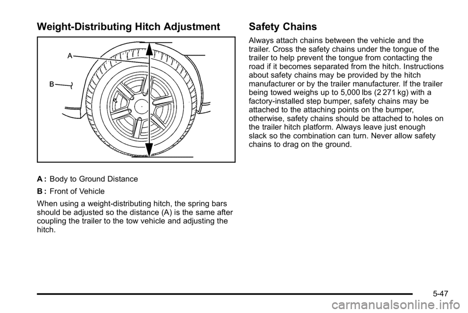
Weight‐Distributing Hitch Adjustment
A :Body to Ground Distance
B : Front of Vehicle
When using a weight-distributing hitch, the spring bars
should be adjusted so the distance (A) is the same after
coupling the trailer to the tow vehicle and adjusting the
hitch.
Safety Chains
Always attach chains between the vehicle and the
trailer. Cross the safety chains under the tongue of the
trailer to help prevent the tongue from contacting the
road if it becomes separated from the hitch. Instructions
about safety chains may be provided by the hitch
manufacturer or by the trailer manufacturer. If the trailer
being towed weighs up to 5,000 lbs (2 271 kg) with a
factory-installed step bumper, safety chains may be
attached to the attaching points on the bumper,
otherwise, safety chains should be attached to holes on
the trailer hitch platform. Always leave just enough
slack so the combination can turn. Never allow safety
chains to drag on the ground.
5-47
Page 373 of 550
Electric Brake Control Wiring
Provisions
These wiring provisions are included with the vehicle as
part of the trailer wiring package. These provisions are
for an electric brake controller. The instrument panel
contains blunt cut wires near the data link connector for
the trailer brake controller. The harness contains the
following wires:
.Dark Blue: Brake Signal to Trailer Connector
.Red/Black: Battery
.Light Blue/White: Brake Switch
.White: Ground
It should be installed by your dealer/retailer or a
qualified service center.
If the vehicle is equipped with an ITBC, the blunt cuts
exist, but are not connected further in the harness. If an
aftermarket trailer brake controller is installed, the ITBC
must be disconnected. Do not power both ITBC and
aftermarket controllers to control the trailer brakes at the
same time.
Trailer Recommendations
Subtract the hitch loads from the Cargo Weight Rating
(CWR). CWR is the maximum weight of the load the
vehicle can carry. It does not include the weight of the
people inside, but you can figure about 150 lbs. (68 kg)
for each passenger. The total cargo load must not be
more than the vehicles CWR.
Weigh the vehicle with the trailer attached, so the
GVWR or GAWR are not exceeded. If using a
weight-distributing hitch, weigh the vehicle without the
spring bars in place.
The best performance is obtained by correctly
spreading out the weight of the load and choosing the
correct hitch and trailer brakes.
For more information see Towing a Trailer
on
page 5‑42.
5-61
Page 480 of 550
.Laundry detergents or dishwashing soaps with
degreasers can leave residue that streaks and
attracts dirt. For liquid cleaners, about 20 drops per
gallon (3.78 L) of water is a good guide. Use only
mild, neutral-pH soaps.
.Too much cleaner that saturates the upholstery.
.Organic solvents such as naptha, alcohol, etc. that
can damage the vehicle's interior.
Fabric/Carpet
Use a vacuum cleaner with a soft brush attachment
frequently to remove dust and loose dirt. A canister
vacuum with a beater bar in the nozzle may only be
used on floor carpet and carpeted floor mats. For any
soil, always try to remove it first with plain water or club
soda. Before cleaning, gently remove as much of the
soil as possible using one of the following techniques:
.For liquids: gently blot the remaining soil with a
paper towel. Allow the soil to absorb into the paper
towel until no more can be removed.
.For solid dry soils: remove as much as possible
and then vacuum.To clean:
1. Saturate a lint-free, clean white cloth with water or club soda.
2. Wring the cloth to remove excess moisture.
3. Start on the outside edge of the soil and gently rub toward the center. Continue cleaning, using a clean
area of the cloth each time it becomes soiled.
4. Continue to gently rub the soiled area until the cleaning cloth remains clean.
5. If the soil is not completely removed, use a mild soap solution and repeat the cleaning process that
was used with plain water.
If any of the soil remains, a commercial fabric cleaner or
spot lifter may be necessary. When a commercial
upholstery cleaner or spot lifter is to be used, test a
small hidden area for colorfastness first. If the locally
cleaned area gives any impression that a ring formation
may result, clean the entire surface.
After the cleaning process has been completed, a paper
towel can be used to blot excess moisture from the
fabric or carpet.
6-106
Page 543 of 550

L
Labeling, Tire Sidewall . . . . . . . . . . . . . . . . . . . . . . . . . . . . . 6-63
LampsCargo . . . . . . . . . . . . . . . . . . . . . . . . . . . . . . . . . . . . . . . . . . . . . 4-14
Daytime Running (DRL) . . . . . . . . . . . . . . . . . . . . . . . . . . 4-11
Dome . . . . . . . . . . . . . . . . . . . . . . . . . . . . . . . . . . . . . . . . . . . . . 4-13
Dome Lamp Override . . . . . . . . . . . . . . . . . . . . . . . . . . . . . 4-14
License Plate . . . . . . . . . . . . . . . . . . . . . . . . . . . . . . . . . . . . . 6-60
Malfunction Indicator . . . . . . . . . . . . . . . . . . . . . . . . . . . . . 4-38
Puddle . . . . . . . . . . . . . . . . . . . . . . . . . . . . . . . . . . . . . . . . . . . . 4-13
Reading . . . . . . . . . . . . . . . . . . . . . . . . . . . . . . . . . . . . . . . . . . 4-14
Lap Belt . . . . . . . . . . . . . . . . . . . . . . . . . . . . . . . . . . . . . . . . . . . 2-31
Lap-Shoulder Belt . . . . . . . . . . . . . . . . . . . . . . . . . . . . . . . . . 2-25
LATCH System for Child Restraints . . . . . . . . . . . . . . . . 2-43
Lighting Entry . . . . . . . . . . . . . . . . . . . . . . . . . . . . . . . . . . . . . . . . . . . . . 4-14
Exit . . . . . . . . . . . . . . . . . . . . . . . . . . . . . . . . . . . . . . . . . . . . . . . 4-14
Lights Airbag Readiness . . . . . . . . . . . . . . . . . . . . . . . . . . . . . . . . . 4-31
Antilock Brake System (ABS) Warning . . . . . . . . . . . . 4-36
Brake System Warning . . . . . . . . . . . . . . . . . . . . . . . . . . . 4-34
Charging System . . . . . . . . . . . . . . . . . . . . . . . . . . . . . . . . . 4-33
Cruise Control . . . . . . . . . . . . . . . . . . . . . . . . . . . . . . . . . . . . 4-42
Exterior Lamps . . . . . . . . . . . . . . . . . . . . . . . . . . . . . . . . . . . 4-10 Lights (cont.)
Flash-to-Pass . . . . . . . . . . . . . . . . . . . . . . . . . . . . . . . . . . . . . . 4-5
Fog Lamps . . . . . . . . . . . . . . . . . . . . . . . . . . . . . . . . . . . . . . . 4-42
High/Low Beam Changer . . . . . . . . . . . . . . . . . . . . . . . . . . 4-5
Highbeam On . . . . . . . . . . . . . . . . . . . . . . . . . . . . . . . . . . . . . 4-42
Oil Pressure . . . . . . . . . . . . . . . . . . . . . . . . . . . . . . . . . . . . . . 4-41
On Reminder . . . . . . . . . . . . . . . . . . . . . . . . . . . . . . . . . . . . . 4-11
Passenger Airbag Status Indicator . . . . . . . . . . . . . . . . 4-32
Safety Belt Reminders . . . . . . . . . . . . . . . . . . . . . . . . . . . . 4-30
Security . . . . . . . . . . . . . . . . . . . . . . . . . . . . . . . . . . . . . . . . . . 4-42
StabiliTrak
®Indicator . . . . . . . . . . . . . . . . . . . . . . . . . . . . . 4-36
Tire Pressure . . . . . . . . . . . . . . . . . . . . . . . . . . . . . . . . . . . . . 4-37
Tow/Haul Mode . . . . . . . . . . . . . . . . . . . . . . . . . . . . . . . . . . . 4-43
Loading Your Vehicle . . . . . . . . . . . . . . . . . . . . . . . . . . . . . . 5-31
Locking Rear Axle . . . . . . . . . . . . . . . . . . . . . . . . . . . . . . . . . . .5-8
Locks
Delayed Locking . . . . . . . . . . . . . . . . . . . . . . . . . . . . . . . . . . 3-11
Door . . . . . . . . . . . . . . . . . . . . . . . . . . . . . . . . . . . . . . . . . . . . . . 3-10
Lockout Protection . . . . . . . . . . . . . . . . . . . . . . . . . . . . . . . . 3-13
Power Door . . . . . . . . . . . . . . . . . . . . . . . . . . . . . . . . . . . . . . . 3-11
Programmable Automatic Door Locks . . . . . . . . . . . . 3-11
Rear Door Security Locks . . . . . . . . . . . . . . . . . . . . . . . . 3-12
Loss of Control . . . . . . . . . . . . . . . . . . . . . . . . . . . . . . . . . . . . 5-11
Lower Anchors and Tethers for Children . . . . . . . . . . . 2-43
Lumbar
Power Controls . . . . . . . . . . . . . . . . . . . . . . . . . . . . . . . . . . . . 2-4
i - 9