wiring GMC SIERRA DENALI 2010 Owners Manual
[x] Cancel search | Manufacturer: GMC, Model Year: 2010, Model line: SIERRA DENALI, Model: GMC SIERRA DENALI 2010Pages: 550, PDF Size: 4.17 MB
Page 108 of 550
Adding Equipment to Your
Airbag-Equipped Vehicle
Q: Is there anything I might add to or change aboutthe vehicle that could keep the airbags from
working properly?
A: Yes. If you add things that change the vehicle's
frame, bumper system, height, front end or side
sheet metal, they may keep the airbag system from
working properly. Changing or moving any parts of
the front seats, safety belts, the airbag sensing and
diagnostic module, steering wheel, instrument panel,
roof-rail airbag modules, ceiling headliner or pillar
garnish trim, overhead console, front sensors, side
impact sensors, rollover sensor module, or airbag
wiring can affect the operation of the airbag system.
In addition, the vehicle may have a passenger
sensing system for the right front passenger
position, which includes sensors that are part of the
passenger seat. The passenger sensing system
may not operate properly if the original seat trim is
replaced with non-GM covers, upholstery or trim,
or with GM covers, upholstery or trim designed for a
different vehicle. Any object, such as an aftermarket
seat heater or a comfort enhancing pad or device,
installed under or on top of the seat fabric, could
also interfere with the operation of the passenger
sensing system. This could either prevent proper deployment of the passenger airbag(s) or prevent
the passenger sensing system from properly turning
off the passenger airbag(s). See
Passenger Sensing
System on page 2‑66.
If you have any questions, call Customer
Assistance. The phone numbers and addresses for
Customer Assistance are in Step Two of the
Customer Satisfaction Procedure in this manual.
See Customer Satisfaction Procedure on page 8‑2.
If the vehicle has rollover roof-rail airbags, see
Different Size Tires and Wheels
on page 6‑82for
additional important information.
Q: Because I have a disability, I have to get my vehicle modified. How can I find out whether this
will affect my airbag system?
A: If you have questions, call Customer Assistance.
The phone numbers and addresses for Customer
Assistance are in Step Two of the Customer
Satisfaction Procedure in this manual. See
Customer Satisfaction Procedure on page 8‑2.
In addition, your dealer/retailer and the service manual
have information about the location of the airbag
sensors, sensing and diagnostic module and airbag
wiring.
2-72
Page 159 of 550
Disconnecting the Rear Vision Camera
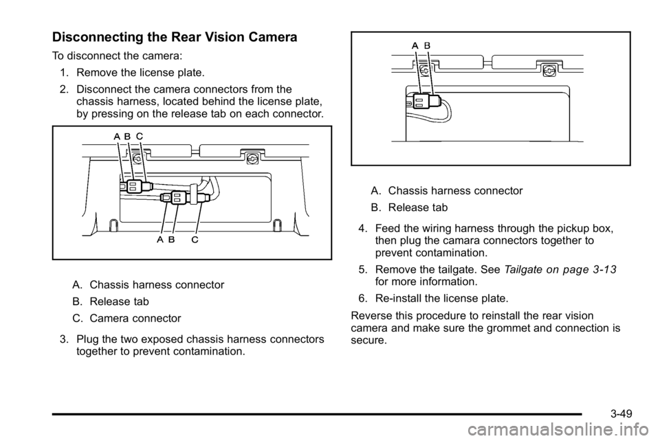
To disconnect the camera:1. Remove the license plate.
2. Disconnect the camera connectors from the chassis harness, located behind the license plate,
by pressing on the release tab on each connector.
A. Chassis harness connector
B. Release tab
C. Camera connector
3. Plug the two exposed chassis harness connectors together to prevent contamination.
A. Chassis harness connector
B. Release tab
4. Feed the wiring harness through the pickup box, then plug the camara connectors together to
prevent contamination.
5. Remove the tailgate. See Tailgate
on page 3‑13for more information.
6. Re‐install the license plate.
Reverse this procedure to reinstall the rear vision
camera and make sure the grommet and connection is
secure.
3-49
Page 203 of 550
Airbag Readiness Light
The system checks the airbag's electrical system for
possible malfunctions. If the light stays on it indicates
there is an electrical problem. The system check
includes the airbag sensor, the pretensioners, the
airbag modules, the wiring and the crash sensing and
diagnostic module. For more information on the airbag
system, seeAirbag System on page 2‑56.
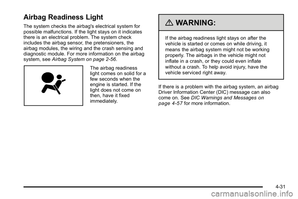
The airbag readiness
light comes on solid for a
few seconds when the
engine is started. If the
light does not come on
then, have it fixed
immediately.
{WARNING:
If the airbag readiness light stays on after the
vehicle is started or comes on while driving, it
means the airbag system might not be working
properly. The airbags in the vehicle might not
inflate in a crash, or they could even inflate
without a crash. To help avoid injury, have the
vehicle serviced right away.
If there is a problem with the airbag system, an airbag
Driver Information Center (DIC) message can also
come on. See DIC Warnings and Messages
on
page 4‑57for more information.
4-31
Page 230 of 550
BATTERY LOW START VEHICLE
When the vehicle’s battery is severely discharged, this
message will display and four chimes will sound. Start
the vehicle immediately. If the vehicle is not started and
the battery continues to discharge, the climate controls,
heated seats, and audio systems will shut off and the
vehicle may require a jump start. These systems will
function again after the vehicle is started.
CHANGE ENGINE OIL SOON
This message displays when the engine oil needs to be
changed. When you change the engine oil, be sure to
reset the CHANGE ENGINE OIL SOON message. See
Engine Oil Life System
on page 6‑20for information on
how to reset the message. See Engine Oilon
page 6‑18and Scheduled Maintenanceon page 7‑3for more information.
CHECK TRAILER WIRING
On vehicles with the Integrated Trailer Brake Control
(ITBC) system, this message may display and a chime
may sound when one of the following conditions exists:
.A trailer with electric brakes becomes
disconnected from the vehicle.
‐If the disconnect occurs while the vehicle is
stopped, this message clears itself after a
short time.
‐ If the disconnect occurs while the vehicle is
moving, this message stays on until the ignition
is turned off.
.There is a short in the wiring to the electric trailer
brakes.
When this message displays, power is no longer
available to the trailer brakes.
As soon as it is safe to do so, carefully pull your vehicle
over to the side of the road and turn the ignition off.
Check the wiring connection to the trailer and turn the
ignition back on. This message clears if the trailer is
reconnected. This message also clears if you
acknowledge it. If this message still displays, either
your vehicle or the trailer needs service. See your
dealer/retailer.
See “Integrated Trailer Brake Control System” under
Towing a Trailer
on page 5‑42for more information.
4-58
Page 236 of 550
SERVICE TRAILER BRAKE SYSTEM
On vehicles with the Integrated Trailer Brake Control
(ITBC) system, this message displays and a chime
sounds when there is a problem with the ITBC system.
When this message displays, power is no longer
available to the trailer brakes.
As soon as it is safe to do so, carefully pull your vehicle
over to the side of the road and turn the ignition off.
Check the wiring connection to the trailer and turn the
ignition back on. If this message still displays, either
your vehicle or the trailer needs service. See your
dealer/retailer.
See“Integrated Trailer Brake Control System” under
Towing a Trailer
on page 5‑42for more information.
STABILITRAK OFF
If your vehicle has StabiliTrak, this message displays
when you turn off StabiliTrak, or when the stability
control has been automatically disabled. To limit wheel
spin and realize the full benefits of the stability
enhancement system, you should normally leave
StabiliTrak on. However, you should turn StabiliTrak off
if your vehicle gets stuck in sand, mud, ice, or snow and
you want to rock your vehicle to attempt to free it, or if
you are driving in extreme off-road conditions and
require more wheel spin. See If Your Vehicle is Stuck in Sand, Mud, Ice, or Snow
on page 5‑6. To turn the
StabiliTrak system on or off, see StabiliTrak®Systemon page 5‑6.
There are several conditions that can cause this
message to appear.
.One condition is overheating, which could occur if
StabiliTrak activates continuously for an extended
period of time.
.The message also displays if the brake system
warning light is on. See Brake System Warning
Light on page 4‑34.
.The message could display if the stability system
takes longer than usual to complete its diagnostic
checks due to driving conditions.
.The message displays if an engine or vehicle
related problem has been detected and the vehicle
needs service. See your dealer/retailer.
The message turns off as soon as the conditions that
caused the message to be displayed are no longer
present.
4-64
Page 364 of 550
All DIC warning and service messages must first be
acknowledged by the driver by pressing the odometer
trip stem or the DIC Vehicle Information button
(if equipped) before the Trailer Brake Display Page can
be displayed and Trailer Gain can be adjusted.
TRAILER GAIN–This setting is displayed anytime the
Trailer Brake Display Page is active. This setting can be
adjusted from 0.0 to 10.0 with either a trailer connected
or disconnected. To adjust the Trailer Gain, press one of
the Trailer Gain adjustment buttons located on the
Trailer Brake Control Panel. Press and hold a gain
button to cause the Trailer Gain to continuously adjust.
To turn the output to the trailer off, adjust the Trailer
Gain setting to 0.0 (zero).
0.0 (zero) gain is the factory default setting. To properly
adjust trailer gain, see the Trailer Gain Adjustment
Procedure later in this section.
TRAILER OUTPUT –This is displayed any time a trailer
with electric brakes is connected. Output to the electric
brakes is based on the amount of vehicle braking
present and relative to the Trailer Gain setting. Output is
displayed from 0 to 10 bars for each gain setting. The Trailer Output will indicate
“- - - - - -“on the Trailer
Brake Display Page whenever the following occur:
.No trailer is connected.
.A trailer without electric brakes is connected (no
DIC message is displayed).
.A trailer with electric brakes has become
disconnected (a CHECK TRAILER WIRING
message will also be displayed on the DIC).
.There is a fault present in the wiring to the electric
trailer brakes (a CHECK TRAILER WIRING
message will also be displayed on the DIC).
.There is a fault in the ITBC system (a SERVICE
TRAILER BRAKE SYSTEM message will also be
displayed in the DIC).
Manual Trailer Brake Apply
The Manual Trailer Brake Apply Lever is located on the
Trailer Brake Control Panel and is used to apply the
trailer ’s electric brakes independent of the vehicle’ s
brakes. This lever is used in the Trailer Gain Adjustment
Procedure to properly adjust the power output to the
trailer brakes. Sliding the lever to the left will apply only
the trailer brakes. The power output to the trailer is
indicated in the Trailer Brake Display Page in the DIC.
If the vehicle’s service brakes are applied while using
the Manual Trailer Brake Apply Lever, the trailer output
power will be the greater of the two.
5-52
Page 366 of 550
6. Adjust the Trailer Gain to just below the point oftrailer wheel lock-up, indicated by trailer wheel
squeal or tire smoke when a trailer wheel locks.
Trailer wheel lock-up may not occur if towing a
heavily loaded trailer. In this case, adjust the
Trailer Gain to the highest allowable setting for the
towing condition.
7. Re-adjust Trailer Gain any time vehicle loading, trailer loading or road surface conditions change or
if trailer wheel lock-up is noticed at any time while
towing.
Other ITBC Related DIC Messages
In addition to displaying TRAILER GAIN and TRAILER
OUTPUT through the DIC, trailer connection and ITBC
system status is displayed in the DIC.
TRAILER CONNECTED –This message will be briefly
displayed when a trailer with electric brakes is first
connected to the vehicle. This message will
automatically turn off in about ten seconds. The driver
can also acknowledge this message before it
automatically turns off. CHECK TRAILER WIRING
–This message will be
displayed if:
1. The ITBC system first determines connection to a trailer with electric brakes and then the trailer
harness becomes disconnected from the vehicle.
If the disconnect occurs while the vehicle is
stationary, this message will automatically turn off
in about thirty seconds. This message will also turn
off if the driver acknowledges this message off or if
the trailer harness is re-connected.
If the disconnect occurs while the vehicle is
moving, this message will continue until the ignition
is turned off. This message will also turn off if the
driver acknowledges this message off or if the
trailer harness is re-connected.
2. There is an electrical fault in the wiring to the electric trailer brakes. This message will continue
as long as there is an electrical fault in the trailer
wiring. This message will also turn off if the driver
acknowledges this message off.
5-54
Page 367 of 550
To determine if the electrical fault is on the vehicle side
or trailer side of the trailer wiring harness connection,
do the following:1. Disconnect the trailer wiring harness from the vehicle.
2. Turn the ignition OFF.
3. Wait ten seconds, then turn the ignition back to RUN.
4. If the CHECK TRAILER WIRING message re-appears, the electrical fault is on the
vehicle side.
If the CHECK TRAILER WIRING message only
re-appears when connecting the trailer wiring
harness to the vehicle, the electrical fault is on the
trailer side.
SERVICE TRAILER BRAKE SYSTEM –This message
will be displayed when there is a problem with the ITBC
system. If this message persists over multiple ignition
cycles there is problem with the ITBC system. Take the
vehicle to an authorized GM dealer to have the ITBC
system diagnosed and repaired. If either the CHECK TRAILER WIRING or SERVICE
TRAILER BRAKE SYSTEM message is displayed while
driving the vehicle, power is no longer available to the
trailer brakes. When traffic conditions allow, carefully
pull the vehicle over to the side of the road and turn the
ignition off. Check the wiring connection to the trailer
and turn the ignition back on. If either of these
messages continues, either the vehicle or trailer needs
service.
An authorized GM dealer may be able to diagnose and
repair problems with the trailer. However, any diagnosis
and repair of the trailer is not covered under the vehicle
warranty. Please contact your trailer dealer for
assistance with trailer repairs and trailer warranty
information.
5-55
Page 372 of 550
Trailer Wiring Harness
Heavy-Duty Trailer Wiring Harness Package
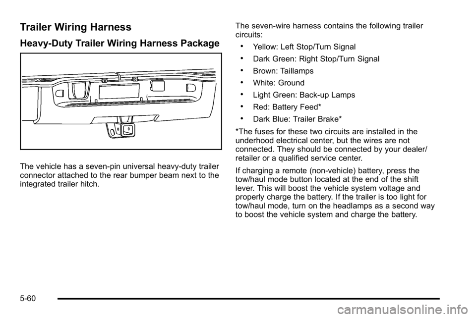
The vehicle has a seven-pin universal heavy-duty trailer
connector attached to the rear bumper beam next to the
integrated trailer hitch.The seven-wire harness contains the following trailer
circuits:
.Yellow: Left Stop/Turn Signal
.Dark Green: Right Stop/Turn Signal
.Brown: Taillamps
.White: Ground
.Light Green: Back-up Lamps
.Red: Battery Feed*
.Dark Blue: Trailer Brake*
*The fuses for these two circuits are installed in the
underhood electrical center, but the wires are not
connected. They should be connected by your dealer/
retailer or a qualified service center.
If charging a remote (non-vehicle) battery, press the
tow/haul mode button located at the end of the shift
lever. This will boost the vehicle system voltage and
properly charge the battery. If the trailer is too light for
tow/haul mode, turn on the headlamps as a second way
to boost the vehicle system and charge the battery.
5-60
Page 373 of 550
Electric Brake Control Wiring
Provisions
These wiring provisions are included with the vehicle as
part of the trailer wiring package. These provisions are
for an electric brake controller. The instrument panel
contains blunt cut wires near the data link connector for
the trailer brake controller. The harness contains the
following wires:
.Dark Blue: Brake Signal to Trailer Connector
.Red/Black: Battery
.Light Blue/White: Brake Switch
.White: Ground
It should be installed by your dealer/retailer or a
qualified service center.
If the vehicle is equipped with an ITBC, the blunt cuts
exist, but are not connected further in the harness. If an
aftermarket trailer brake controller is installed, the ITBC
must be disconnected. Do not power both ITBC and
aftermarket controllers to control the trailer brakes at the
same time.
Trailer Recommendations
Subtract the hitch loads from the Cargo Weight Rating
(CWR). CWR is the maximum weight of the load the
vehicle can carry. It does not include the weight of the
people inside, but you can figure about 150 lbs. (68 kg)
for each passenger. The total cargo load must not be
more than the vehicles CWR.
Weigh the vehicle with the trailer attached, so the
GVWR or GAWR are not exceeded. If using a
weight-distributing hitch, weigh the vehicle without the
spring bars in place.
The best performance is obtained by correctly
spreading out the weight of the load and choosing the
correct hitch and trailer brakes.
For more information see Towing a Trailer
on
page 5‑42.
5-61