engine remove GMC TERRAIN 2014 Owner's Guide
[x] Cancel search | Manufacturer: GMC, Model Year: 2014, Model line: TERRAIN, Model: GMC TERRAIN 2014Pages: 360, PDF Size: 3.93 MB
Page 286 of 360

Black plate (70,1)GMC Terrain/Terrain Denali Owner Manual (GMNA-Localizing-U.S./Canada/
Mexico-6081485) - 2014 - CRC - 12/6/13
10-70 Vehicle Care
{Caution
If the jumper cables are
connected or removed in the
wrong order, electrical shorting
may occur and damage the
vehicle. The repairs would not be
covered by the vehicle warranty.
Always connect and remove the
jumper cables in the correct order,
making sure that the cables do
not touch each other or other
metal.
1. Remote Positive (+) Terminal
2. Remote Negative (−) Terminal
1. The vehicle used to jump startmust have 12-volt battery with a
negative ground.
{Caution
If the other vehicle does not have
a 12-volt system with a negative
ground, both vehicles can be
damaged. Only use a vehicle that
has a 12-volt system with a
negative ground for jump starting.
2. The vehicles should be close enough for the jumper cables to
reach, but the vehicles should
not be touching. Touching could
cause grounding and possible
electrical system damage.
Put both vehicles in P (Park) and
set the parking brake firmly.
3. Unplug accessories plugged into the cigarette lighter or the
accessory power outlet. Turn off the radio and all lamps that are
not needed. Turn off the ignition
on both vehicles.
4. Locate the positive (+) and negative (−) terminals on both
vehicles. Some vehicles have
remote jump starting terminals.{Warning
An electric fan can start up even
when the engine is not running
and can injure you. Keep hands,
clothing and tools away from any
underhood electric fan.
5. The remote positive (+) terminal (1) is located on the
underhood fuse block, on the
driver side. Lift the red cap to
uncover the terminal.
The remote negative (−)
terminal (2) is a stud behind the
metal tab stamped with GND (−)
near the driver side strut tower.
Page 287 of 360

Black plate (71,1)GMC Terrain/Terrain Denali Owner Manual (GMNA-Localizing-U.S./Canada/
Mexico-6081485) - 2014 - CRC - 12/6/13
Vehicle Care 10-71
6. The jumper cables should be ingood working condition with no
loose or missing insulation. The
vehicles could be damaged if
they are not.
7. Connect the red positive (+) cable to the positive (+) terminal
on the vehicle with the dead
battery. Use a remote
positive (+) terminal if the
vehicle has one.
8. Do not let the other end touch metal. Connect it to the
positive (+) terminal of the good
battery. Use a remote
positive (+) terminal if the
vehicle has one.
9. Connect the black negative (−) cable to the negative (−) terminal
of the good battery. Use a
remote negative (−) terminal if
the vehicle has one. Do not let the other end touch
anything until the next step. The
other end of the negative (−)
cable does not go to the dead
battery. It goes to a heavy,
unpainted metal engine part or
to a remote negative (−) terminal
on the vehicle with the dead
battery.
10. Connect the other end of the negative (−) cable away from
the dead battery, but not near
engine parts that move.
11. Start the vehicle with the good battery and run the engine.
12. Press the unlock symbol on the remote keyless entry
transmitter to disarm the
security system, if equipped.
13. Try to start the vehicle that had the dead battery. If it will not
start after a few tries, it needs
service.{Caution
If the jumper cables are
connected or removed in the
wrong order, electrical shorting
may occur and damage the
vehicle. The repairs would not be
covered by the vehicle warranty.
Always connect and remove the
jumper cables in the correct order,
making sure that the cables do
not touch each other or other
metal.
Jumper Cable Removal
Reverse the sequence exactly when
removing the jumper cables.
Page 289 of 360

Black plate (73,1)GMC Terrain/Terrain Denali Owner Manual (GMNA-Localizing-U.S./Canada/
Mexico-6081485) - 2014 - CRC - 12/6/13
Vehicle Care 10-73
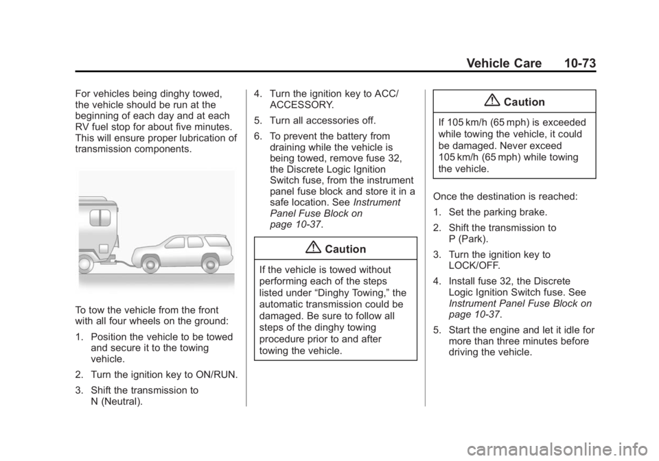
For vehicles being dinghy towed,
the vehicle should be run at the
beginning of each day and at each
RV fuel stop for about five minutes.
This will ensure proper lubrication of
transmission components.
To tow the vehicle from the front
with all four wheels on the ground:
1. Position the vehicle to be towedand secure it to the towing
vehicle.
2. Turn the ignition key to ON/RUN.
3. Shift the transmission to N (Neutral). 4. Turn the ignition key to ACC/
ACCESSORY.
5. Turn all accessories off.
6. To prevent the battery from draining while the vehicle is
being towed, remove fuse 32,
the Discrete Logic Ignition
Switch fuse, from the instrument
panel fuse block and store it in a
safe location. See Instrument
Panel Fuse Block on
page 10-37.
{Caution
If the vehicle is towed without
performing each of the steps
listed under “Dinghy Towing,” the
automatic transmission could be
damaged. Be sure to follow all
steps of the dinghy towing
procedure prior to and after
towing the vehicle.
{Caution
If 105 km/h (65 mph) is exceeded
while towing the vehicle, it could
be damaged. Never exceed
105 km/h (65 mph) while towing
the vehicle.
Once the destination is reached:
1. Set the parking brake.
2. Shift the transmission to P (Park).
3. Turn the ignition key to LOCK/OFF.
4. Install fuse 32, the Discrete Logic Ignition Switch fuse. See
Instrument Panel Fuse Block on
page 10-37.
5. Start the engine and let it idle for more than three minutes before
driving the vehicle.
Page 319 of 360

Black plate (1,1)GMC Terrain/Terrain Denali Owner Manual (GMNA-Localizing-U.S./Canada/
Mexico-6081485) - 2014 - CRC - 12/6/13
Technical Data 12-1
Technical Data
Vehicle Identification
Vehicle IdentificationNumber (VIN) . . . . . . . . . . . . . . 12-1
Service Parts Identification Label . . . . . . . . . . . . . . . . . . . . . . . 12-1
Vehicle Data
Capacities andSpecifications . . . . . . . . . . . . . . 12-2
Engine Drive Belt Routing . . . 12-4
Vehicle Identification
Vehicle Identification
Number (VIN)
This legal identifier is in the front
corner of the instrument panel, on
the left side of the vehicle. It can be
seen through the windshield from
outside. The VIN also appears on
the Vehicle Certification and Service
Parts labels and certificates of title
and registration.
Engine Identification
The eighth character in the VIN is
the engine code. This code
identifies the vehicle's engine,
specifications, and replacement
parts. See “Engine Specifications”
under Capacities and Specifications
on page 12-2 for the vehicle's
engine code.
Service Parts
Identification Label
This label, on the inside of the glove
box, has the following information:
.Vehicle Identification
Number (VIN).
.Model designation.
.Paint information.
.Production options and special
equipment.
Do not remove this label from the
vehicle.